One of the most difficult things with a 3 axis CNC is the motion control. I tried different ways but decided that reinventing the wheel is just to much trouble and using one of the available motion controllers would be the best way.
I first tried FluidNC which is the newest version of Grbl specialized to the ESP32. The problem is that the GEDM uses a Touch TFT display and a feedbackloop for the EDM process and the stock FluidNC firmware just doesn't fit.
I tried multiple times to fork FluidNC and failed two times more.
So I gave the previous version Grbl_Esp32 a chance to bring the axis to live. And the result is promising.
The fork removed all Telnet/XMODEM/WIFI/BLUETOOTH/UART/TMCDRIVER/WEBUI/I2S stuff and reduced the complete Grbl library to a module that integrates well into the Gedm code.
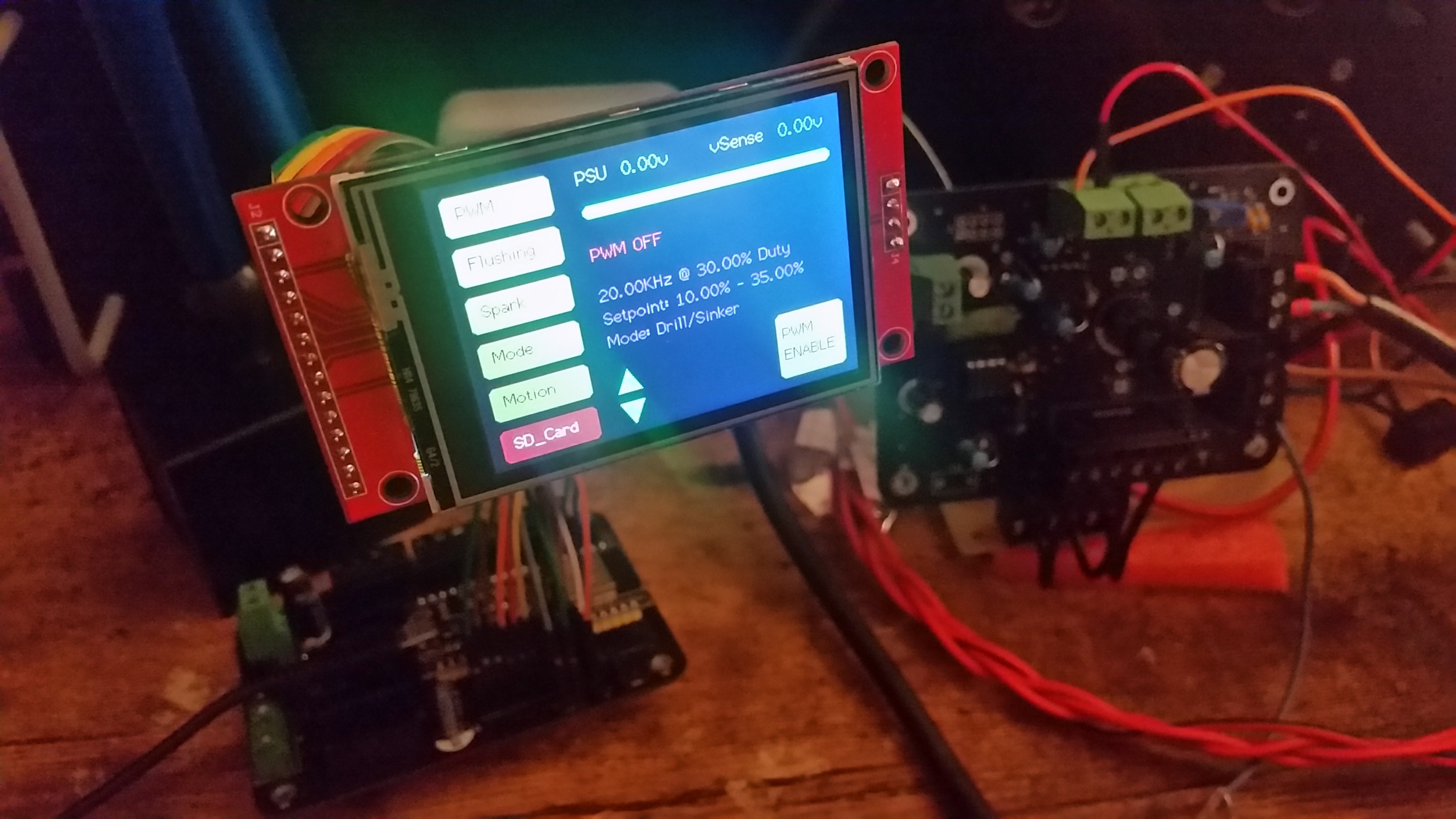
The TFT Touchscreen is isolated on Core0 while Grbl runs on Core1.
It wasn't easy... at all.. Maybe I need a doctor to check for brain aneurysm now... But it looks really good. In the current state the axis can be jogged via touch input, but the UI is still not fully functional. The SD card support needs to be integrated next. But after this is done the real testing can begin.
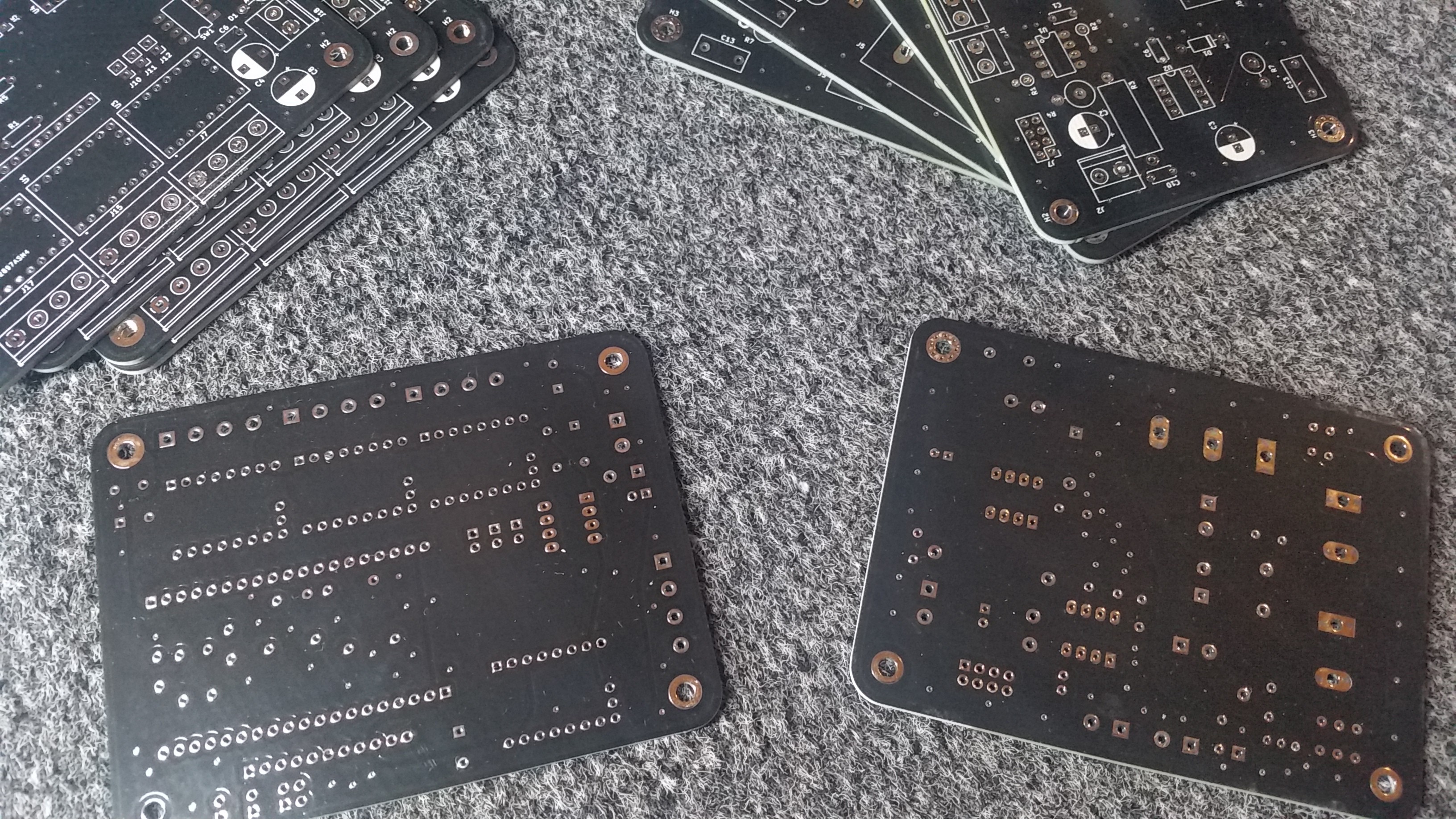
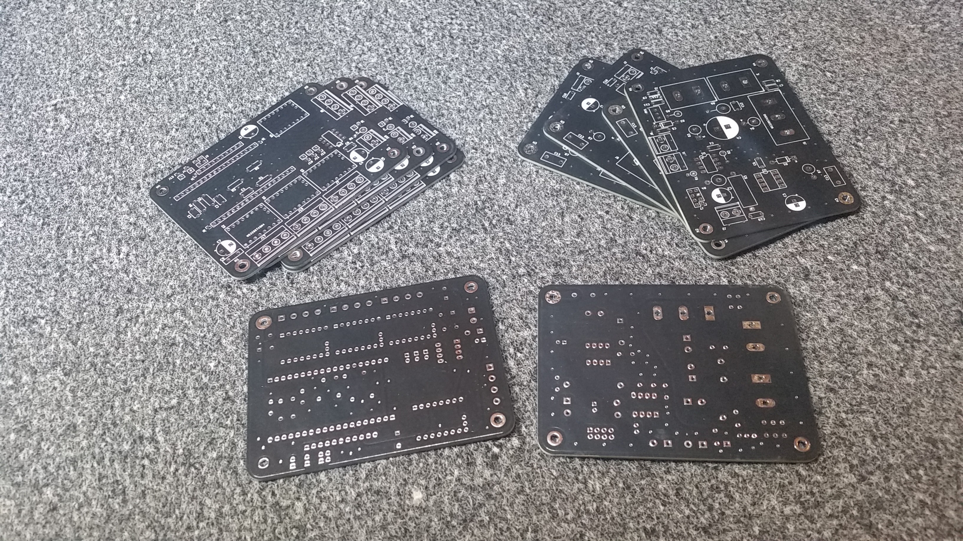
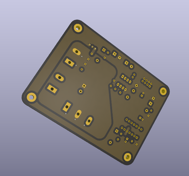
PCBway delivered some boards for this project and what should I say except that they are awesome.
I haven't expected this quality. The boards don't feel like the PCBs found in most products but more like Aluminum. They have a very nice finish and haptic.
And the most important part: They work. :D
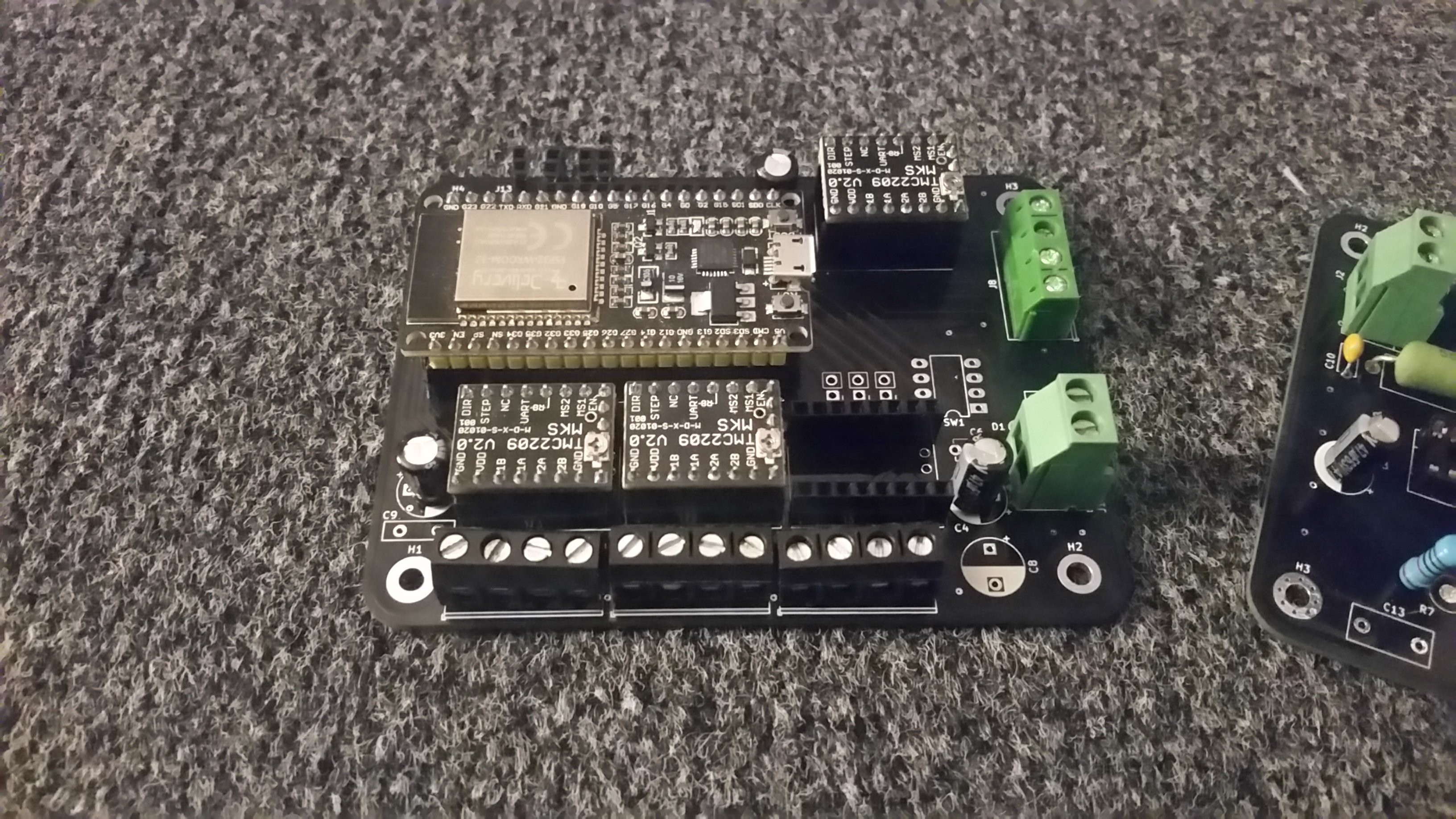
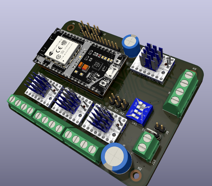
Both boards are 4 layer PCBs with a ground plane and power planes.
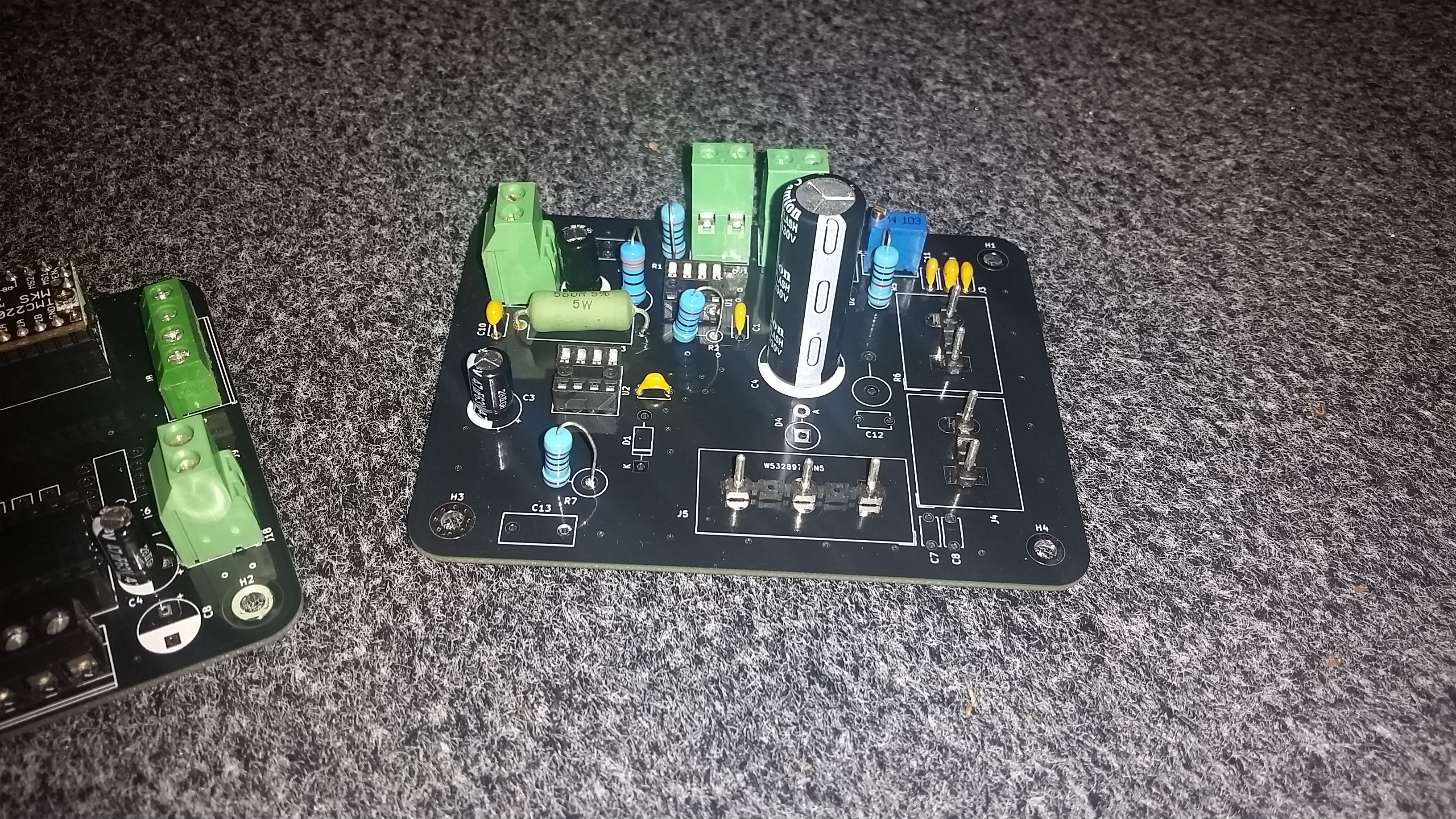
And a look at the mostly finished boards. They are beautiful.
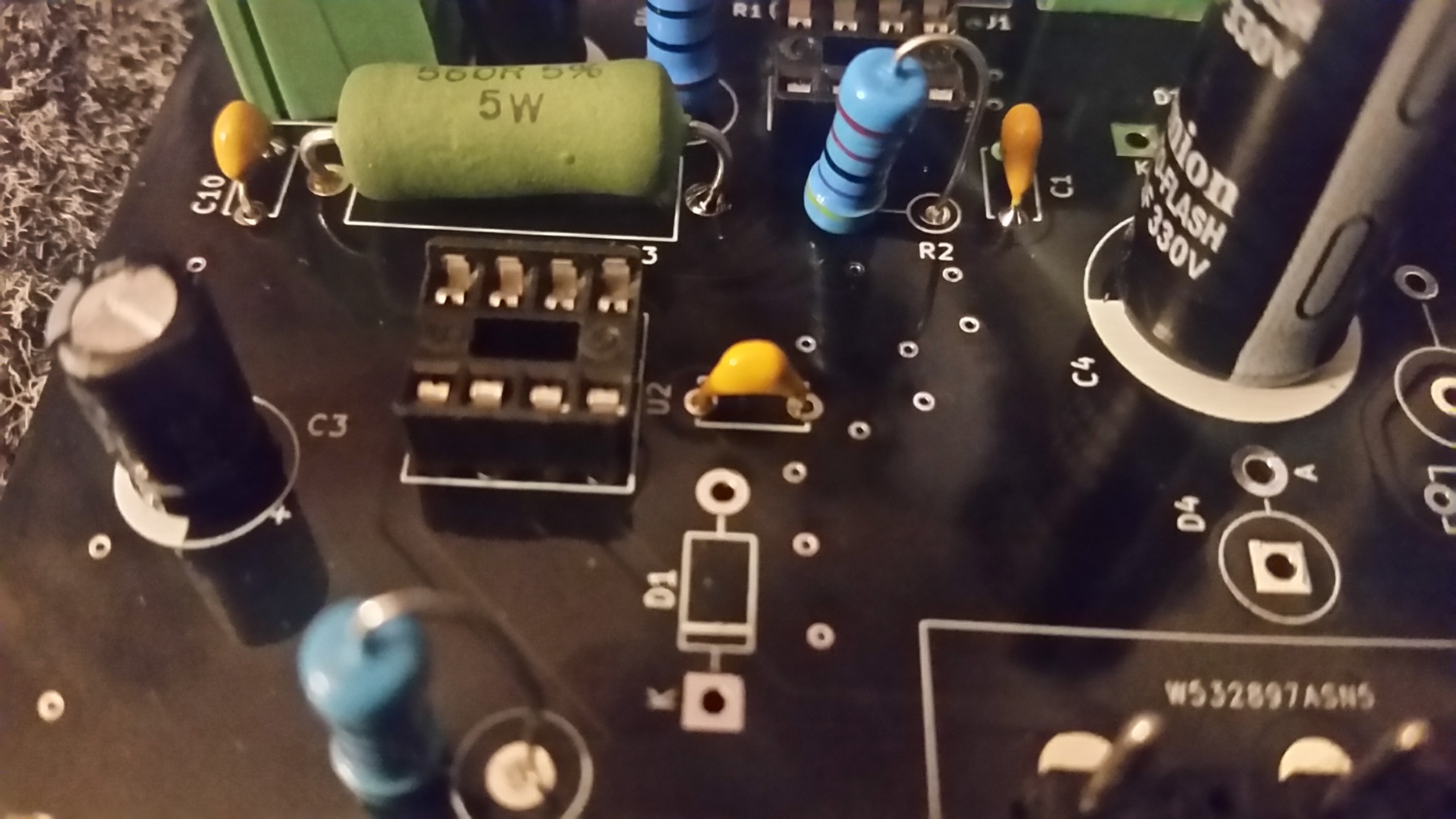
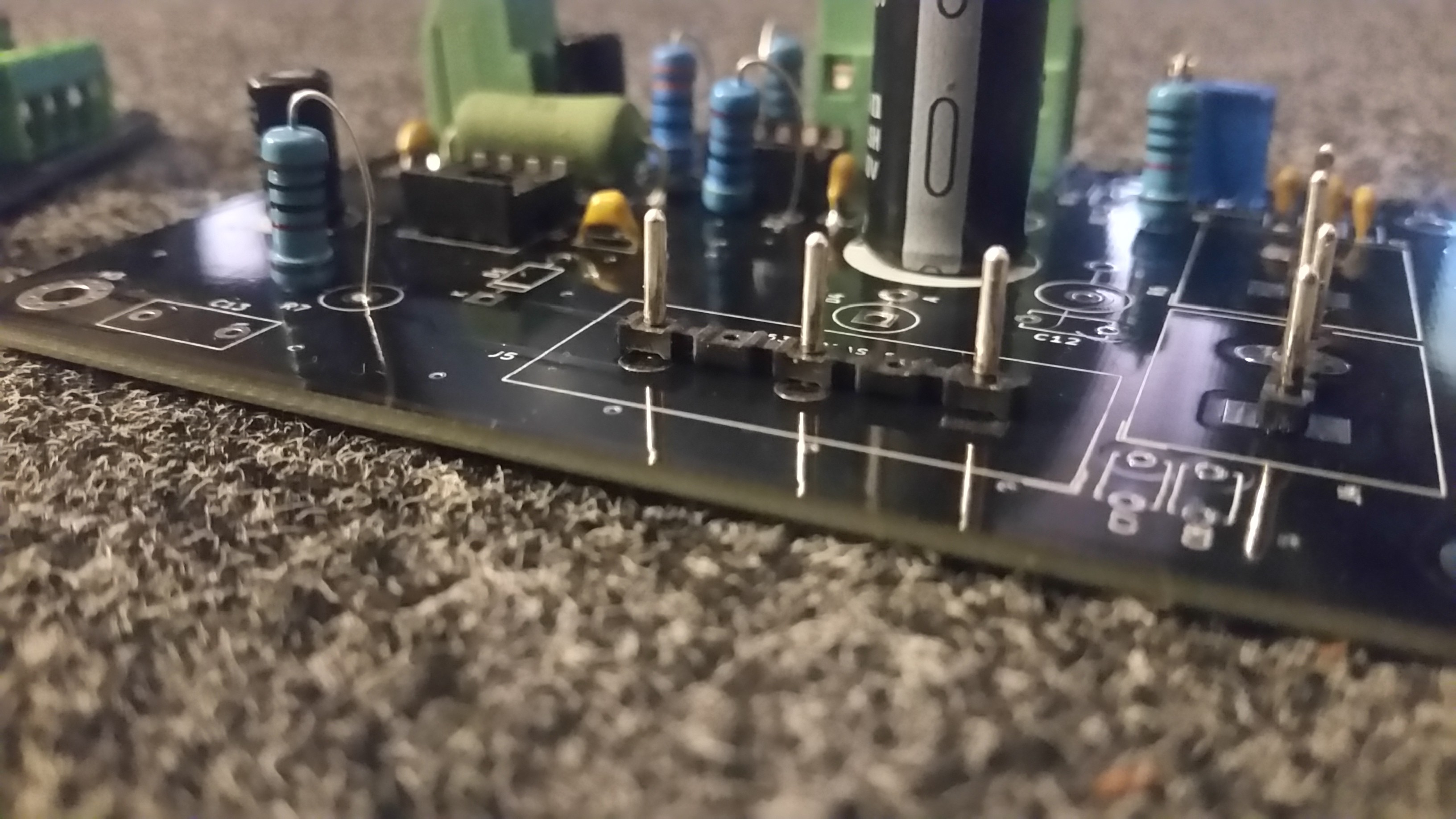
This is the pulseboard. It is an improved version of the old prototype that comes with a high speed optocoupler to isolate the PWM signal and a trimmer poti to adjust the feedback voltage. It has a Zener diode for gate protection and one on the vSense feedback to protect the ESP.
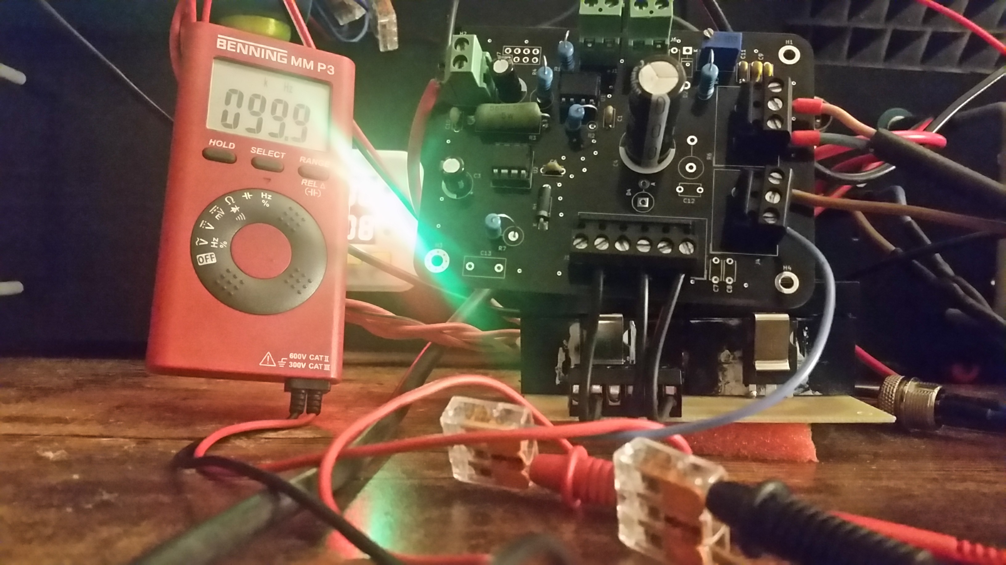
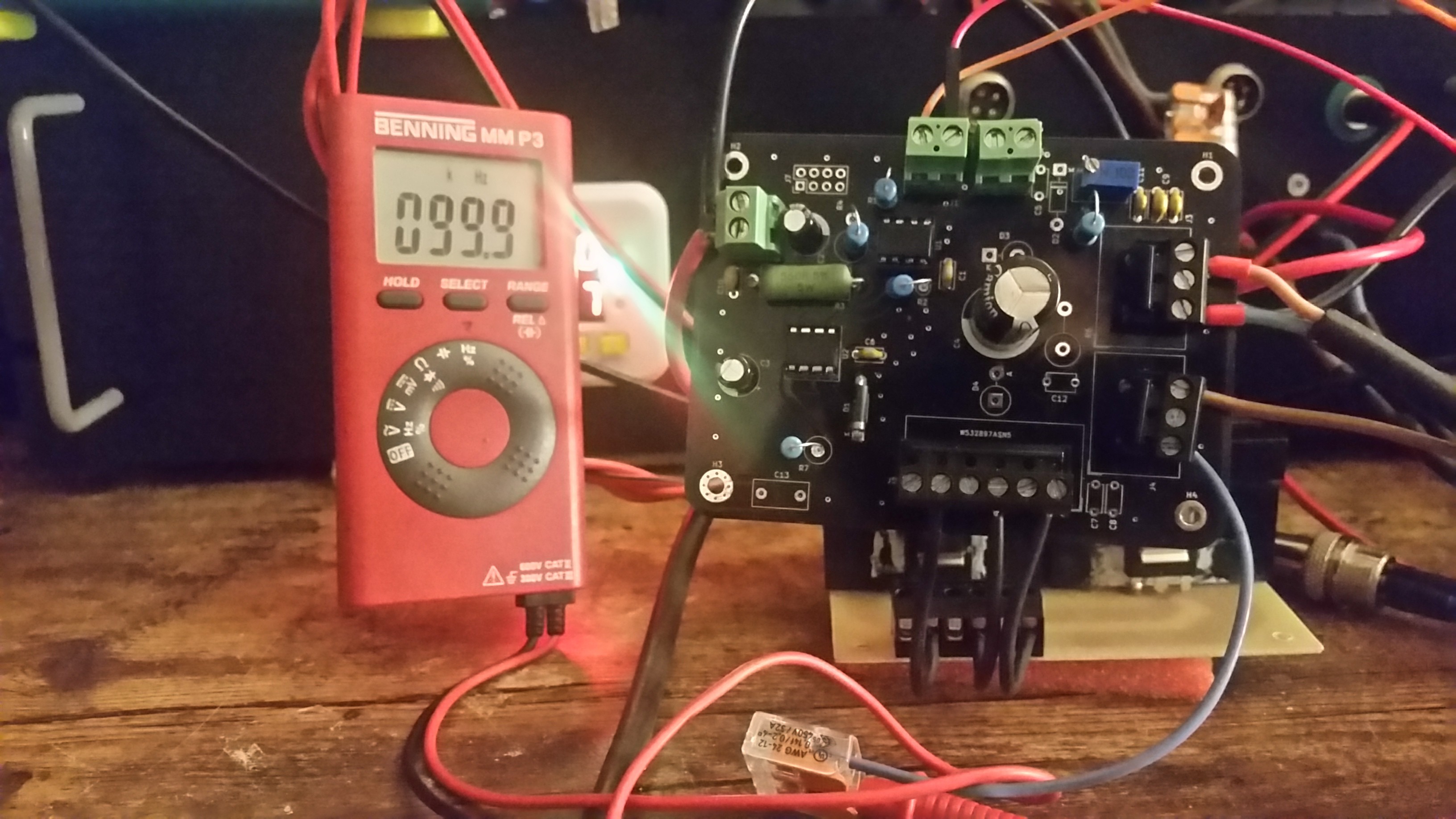
Tests showed that it delivers up to 100khz more or less reliable. 50khz works good. Above 50khz switching losses start. But at 50% duty cycle it delivers the 100khz. It is hard to debug without an oscilloscope. The multi-meter used is everything I have to measure the frequency and above 50khz it sometimes looses track of the frequency.
I'm currently working on two other boards. All of them use different ways to get the sparks. One is a high side switch and one is again a low side switch with a discrete gate driver circuit and a pack of integrated mosfets on the PCB that will make the build process easier.
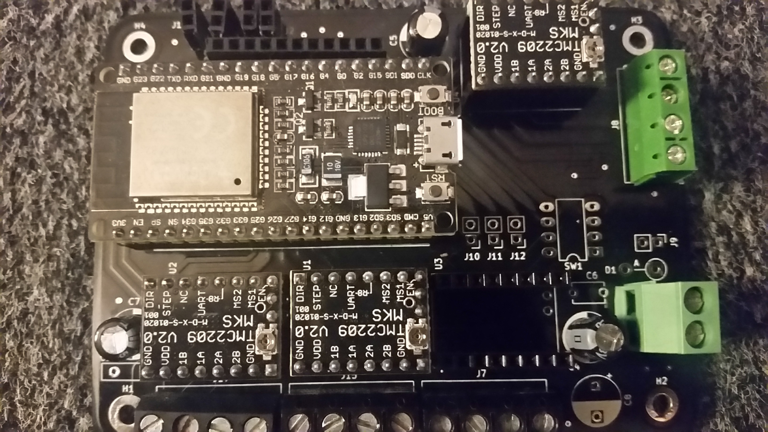
The new motion controller is a beauty too. It reduces the number of PCBs in the controlbox from two to one. In the prototype the ESP32 breakoutboard was mounted below the motion controller. Both boards are now merged into one tiny 4 axis board that offers dip switches to set the microsteps for X,Y and the Spindle. Only Z uses software controlled microsteps. The ESP has no Pins left except one Input-only pin.
The software changed heavily and the motion is now controlled with the fastaccel library that uses hardware generated step signals and can fire step pulses at 200khz.
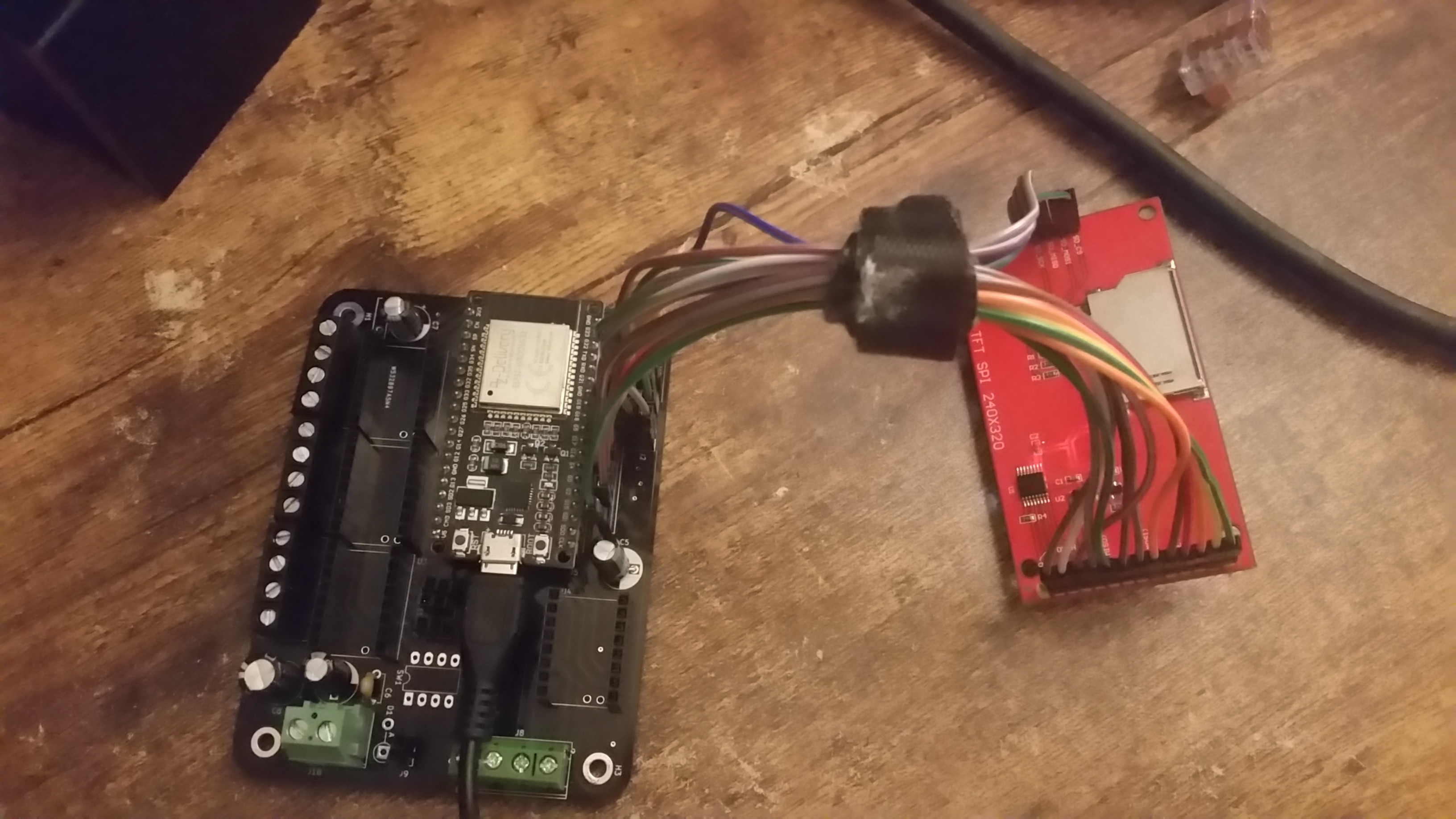
After testing all the connections on the soldered control board with a multimeter it was time to get the display running. Compared to the previous prototypes this was super easy.:
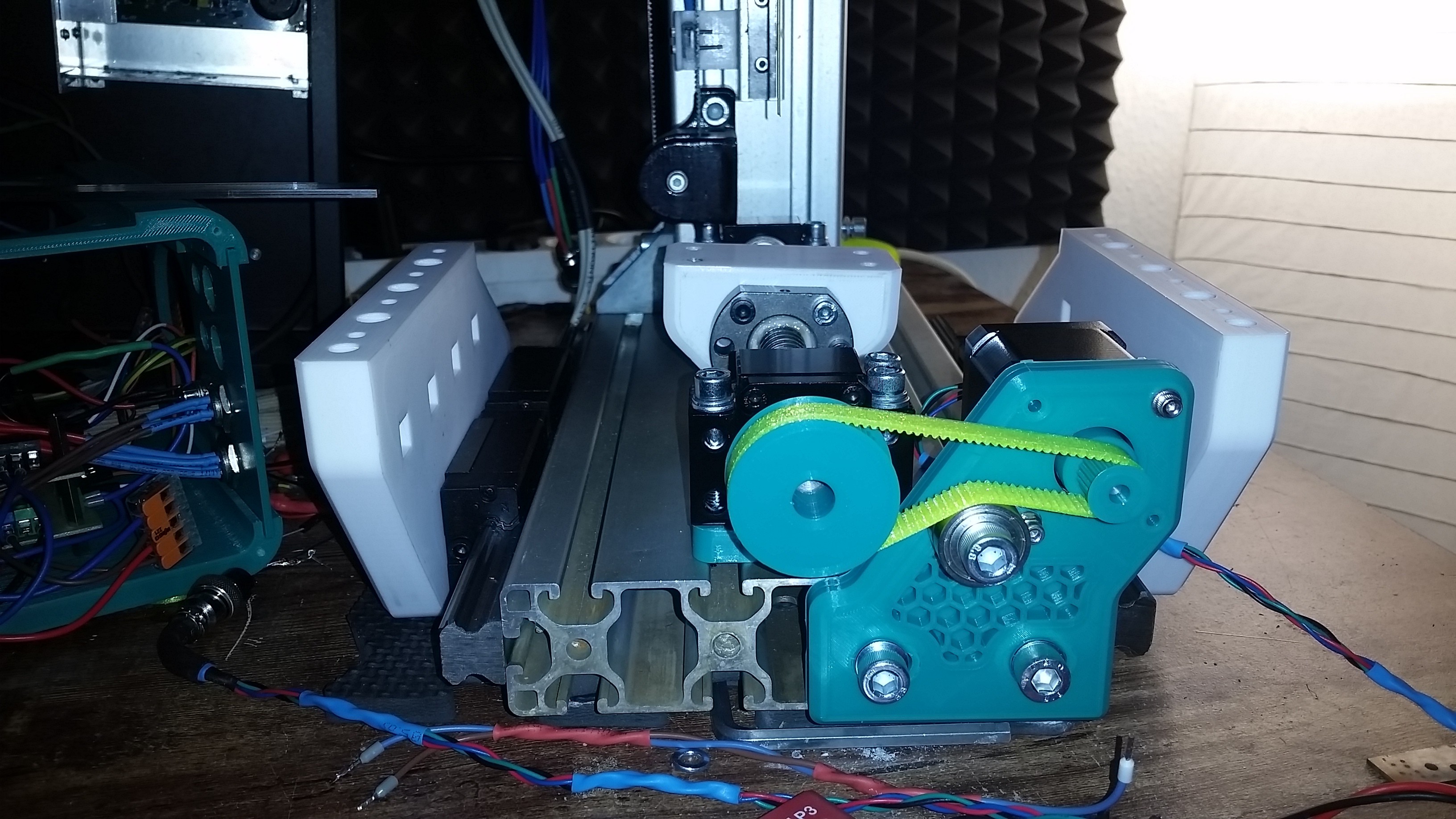
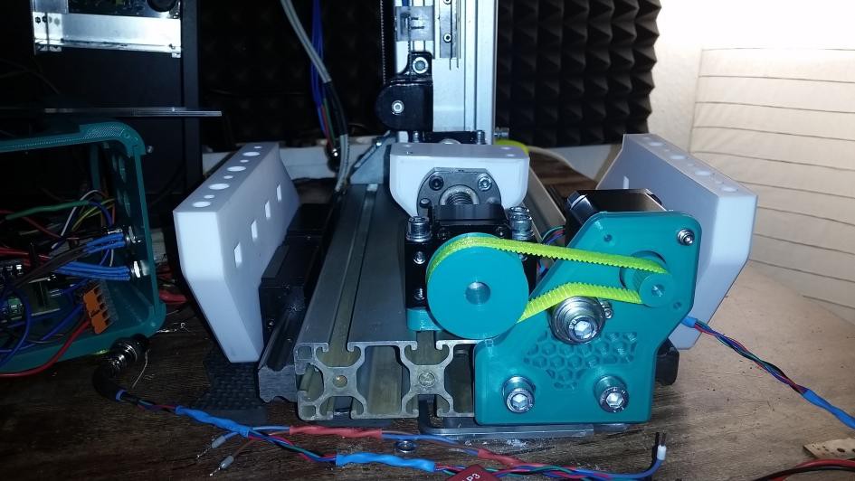
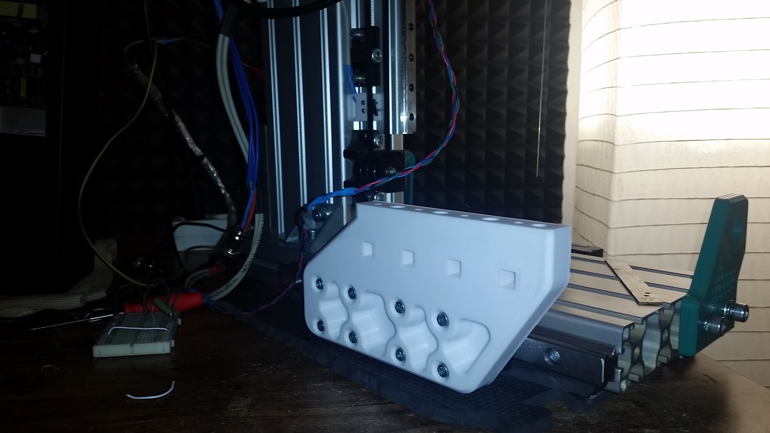
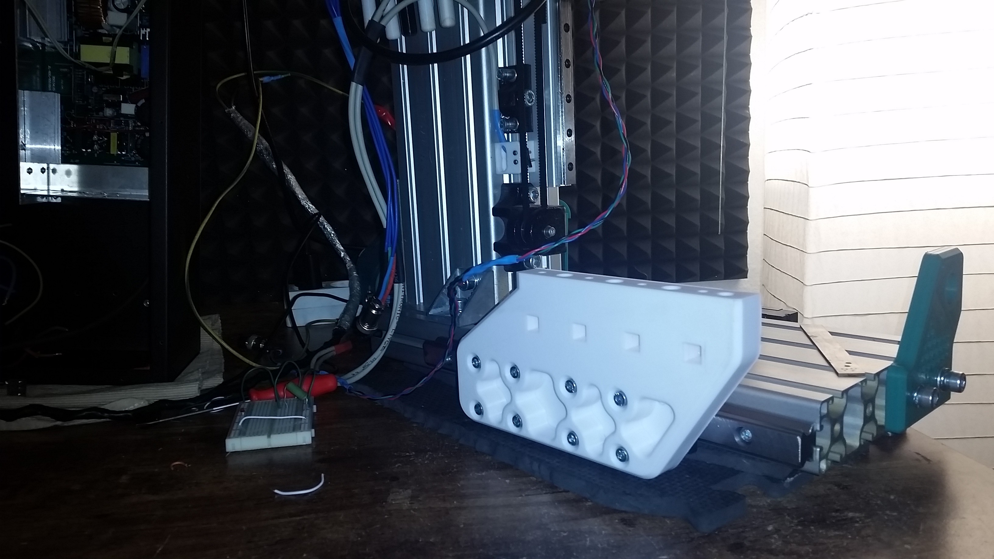
And a little look at the x axis. It is already wired an running. Did some test with a 5kg load and the stepper had no problem at all to drive the axis at all possible microstep settings.
That was a hard ride. So much had to be learned in such a short time but there is light at the end of the road.
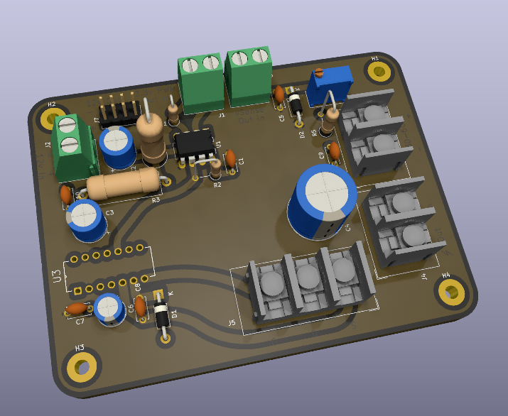
The new pulseboard is mostly finished (some details are still missing like ground via stitching etc). It is a 4 layer PCB with power and ground planes.
It has some pins to add fans and a trimmer poti to adjust the feedback voltage. A 3.3v zener diode protects the ESP pin from wrong settings at the poti.
It is a high side gate driver that is rated for 200v max. With the adjustable feedback voltage the range of the voltages that can be used shifted dramatically. The PWM is isolated with a high speed optocoupler. ( The vSense feedback still isn't )
The first voltage divider design used fixed resistor values and that limited the range to 30-60v. Now it can be 30-200v.
Just a few weeks ago I had zero knowledge about PCBs at all and soldered some prototypes with wires and perfboards. At some point I got sick of it and tried to order the boards online. That wasn't as easy as thought. So much options and new technical terms. And the pricing was insane. I gave up on the idea until someone gave me a few sites that have a good name and are easier to use. I decided to give PCBway a try and the website helped me a lot to understand what gerber files are and what is needed to get a PCB. They also offered tutorials about how to create the files with kicad. Perfect.
That's why I decided to pack the PCB files in the projects final release according to the requirements of this specific vendor. This decision was long ago. Now PCBway offered me free prototyping and I'm very glad about it.
The heart of the G-EDM will get a new design. After merging the 12v PSU into the spark generator it started to produce same heavy voltage drops on the feedback signal sometimes. So the grounding had some issues on the PCB.
The new PCB will have a gnd plane concept with power and logic gnd merged at one point.. Also the mosfet will be switched in a high side configuration. Low side switching may produce oscillation and stuff that is not wanted after the noisy spark flushes to gnd through the mosfet.
Had a hard time figuring out how to create a high speed, high current, high side N-Channel Mosfet switch. Bumpy ride from bootstrapping to charge pumps and level shifters.
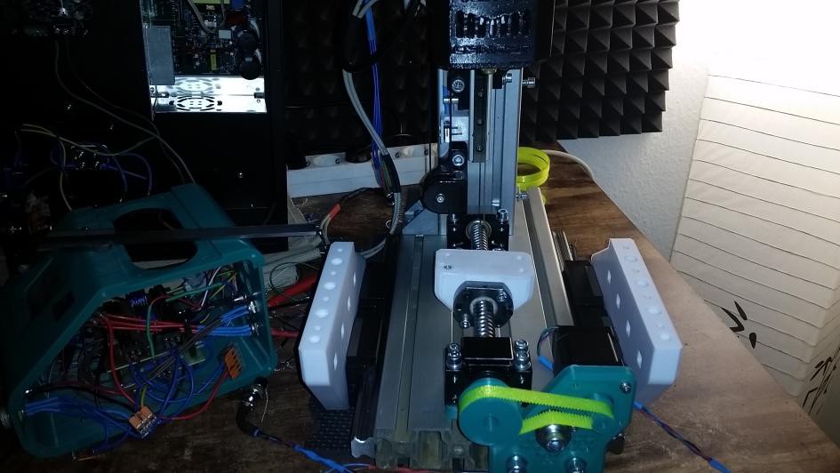
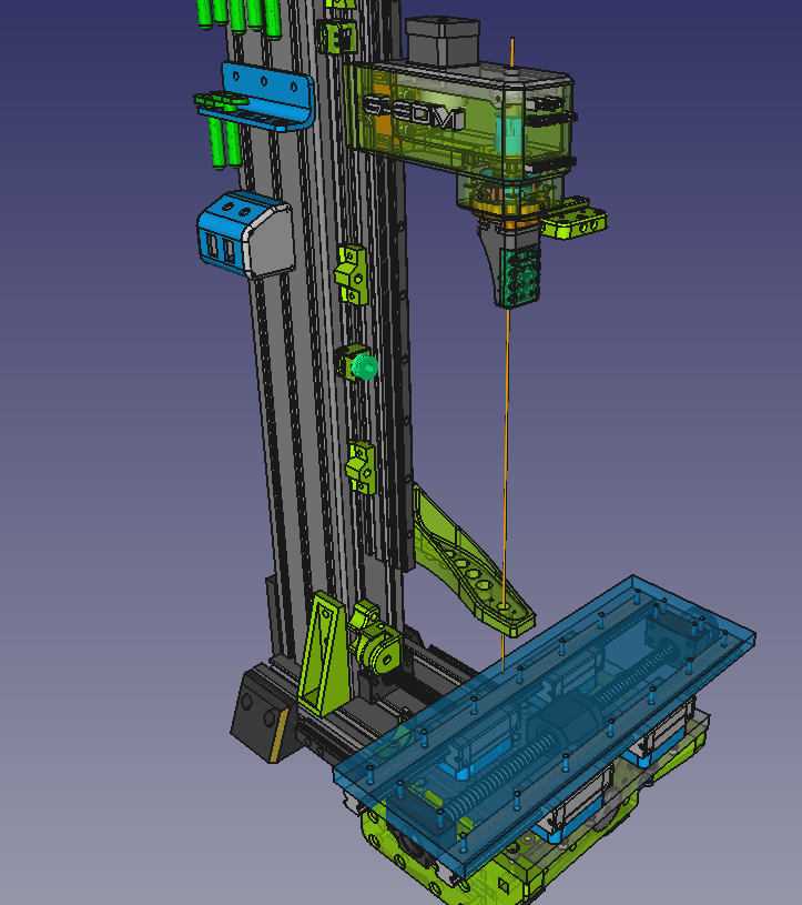
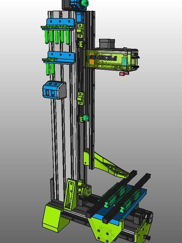
X axis is still printing but the first sidewall is ready. 20mm thick PLA+. Those things are massive.
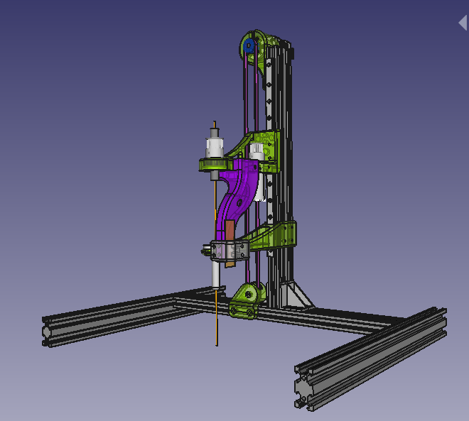
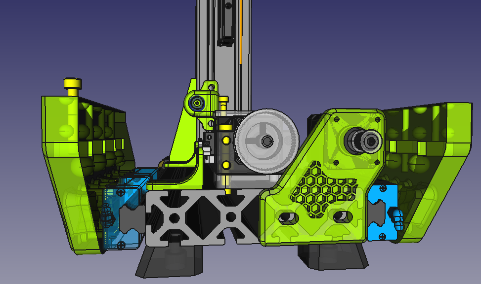
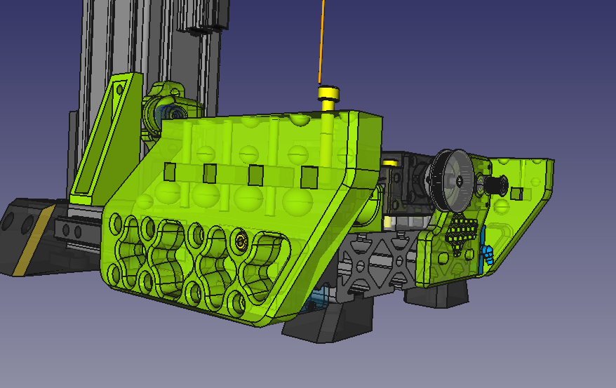
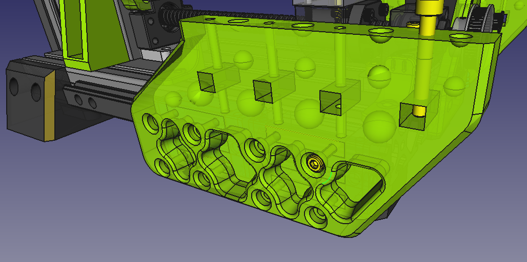
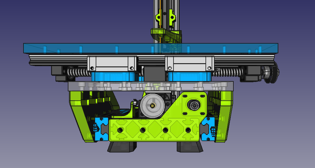
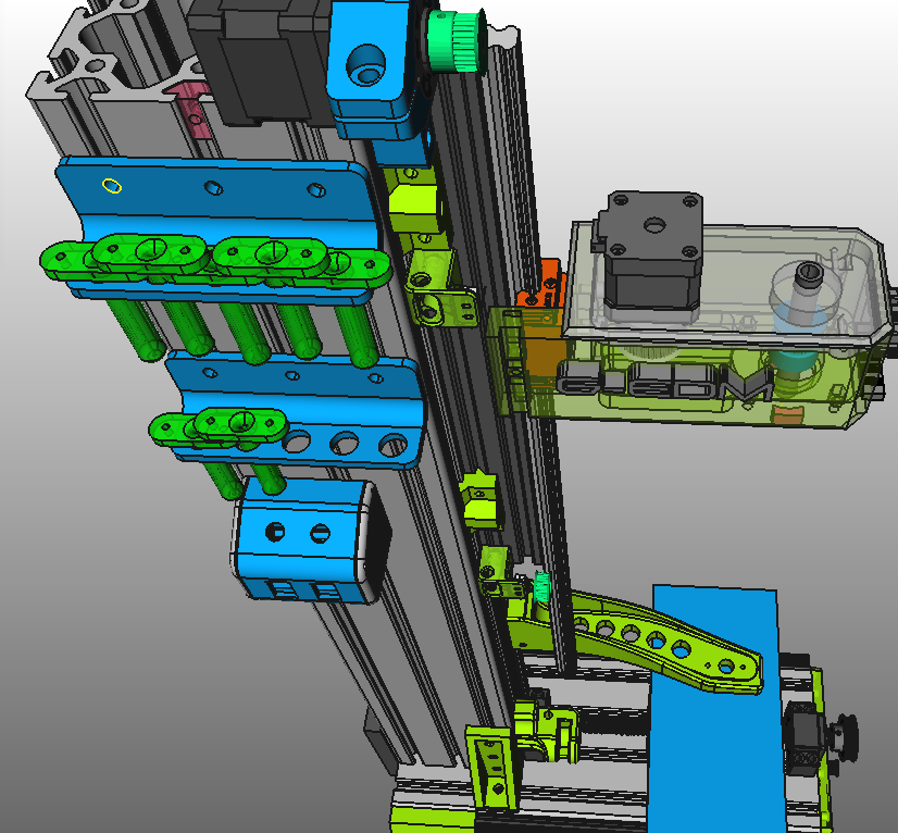
The basic concept of the XY axis is ready and should be finished soon. The linear rail on the Z axis changed from a MGN12 to a HGR15. X and Y will use HGR20 rails.
It will use SFU1605 Ballscrews to move X and Y.
The most important part for me is getting everything ready for wire EDM and I already have some ideas for the design.
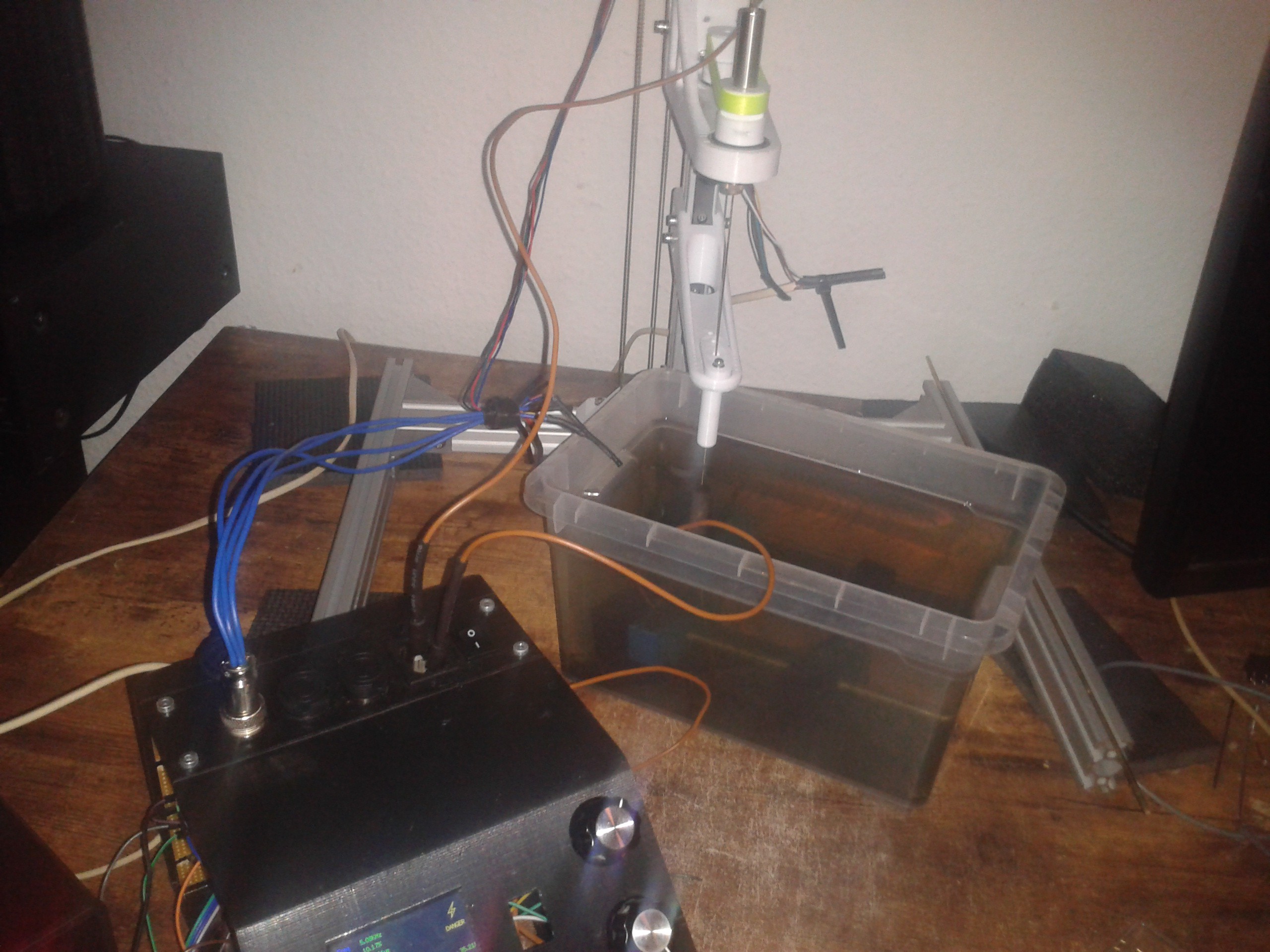
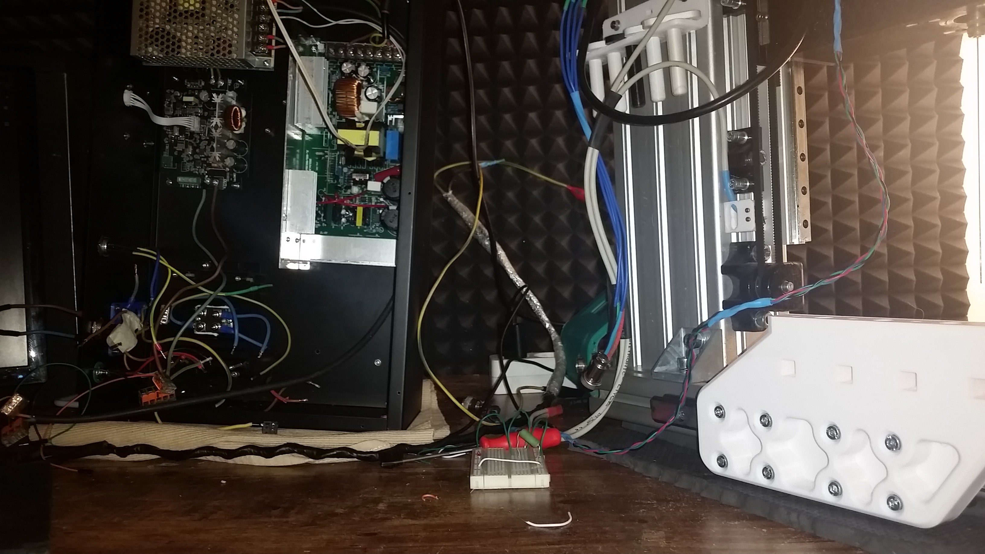
It not just looks cleaner but also requires less external wiring. The stepper motors are powered from a simple adjustable 12v switching PSU that is now mounted inside the 19" spark generator enclosure.
This timelapse video ( 4x speed) shows the wiring of the single axis sinker version.
 gedm-dev