-
1Build the Main PCB
Feel free to use the ready-made gerber files from my github to order a complete assebled PCB from your favorite site
Here are the files: https://github.com/ovidiu4/smart-plant-monitor/tree/main/hardware
-
2(Optional) Build the soil probe PCB
Feel free to use the ready-made gerber files from my github to order a bunch of soil probe PCBs
https://github.com/ovidiu4/smart-plant-monitor/tree/main/hardware
If you'd like to skip this step just know that capacitance can be measures with just a single wire!
Experiment with some dupont wires :)
-
3(Optional) 3D print the case
Feel free to use the ready-made STL files from my github to order or 3D your case
https://github.com/ovidiu4/smart-plant-monitor/tree/main/case
-
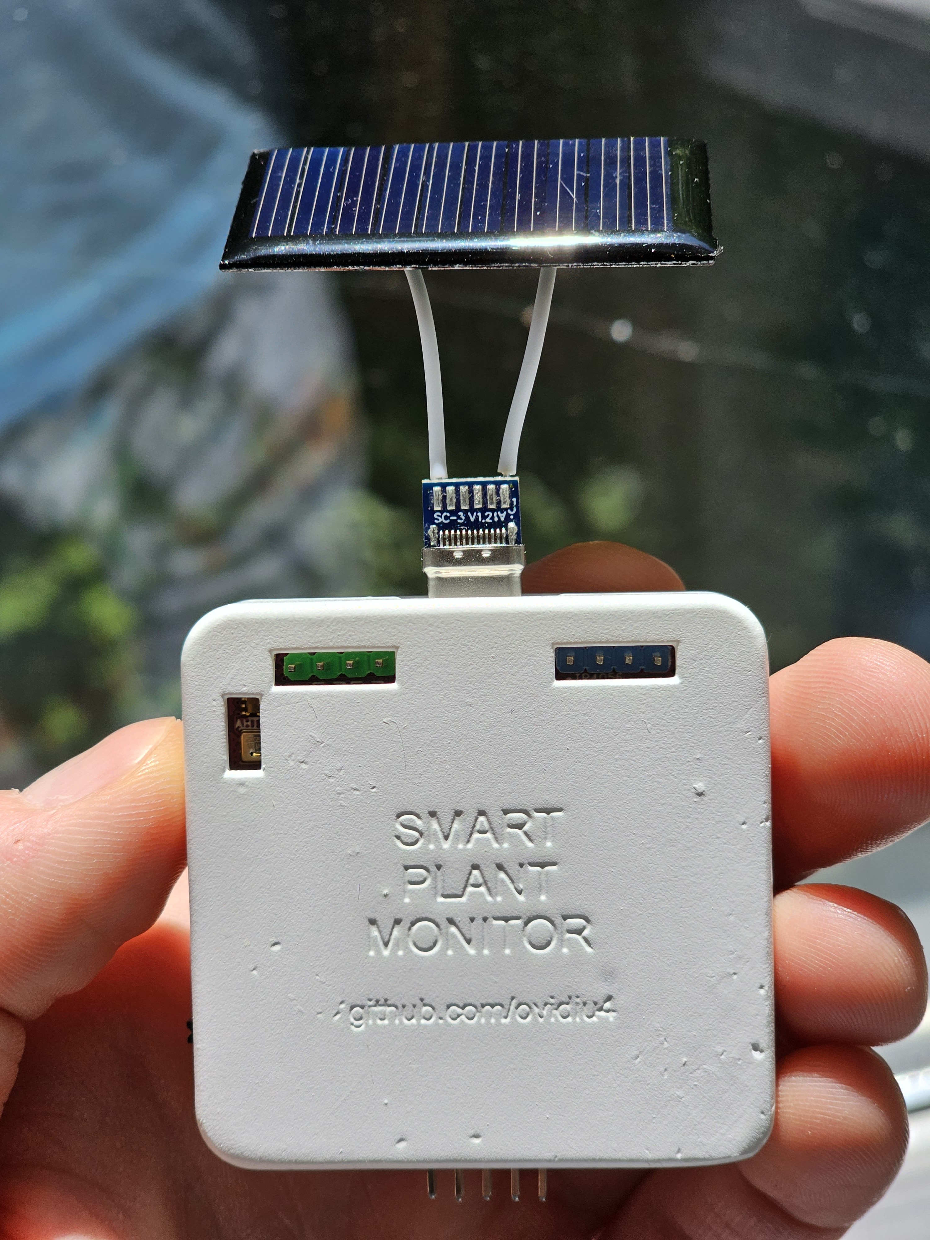
4(Optional) Build the solar charger "module"
For this step you only need a tiny 5V solar pane (25mA should be enough) and a USB-C male connector.
With some basic soldering you could make something like this:
![]()
-
5Assemble the board, battery and case together
If you opted to build a complete project like i did, now is the time to asseble everything together.
The case has specific slots for the battery, display and the PCB to fit in so keep that in mind in case you decided to use different components
ESP32 Powered Smart Plant Monitor
With E-Ink display and capacitive, replaceable soil probes
 Ovidiu
Discussions
Become a Hackaday.io Member
Create an account to leave a comment. Already have an account? Log In.