joey castillo
-
Open Sourcing the Feather Low Energy and the Feather Op Amp Lab
06/06/2023 at 18:28 • 0 commentsI'd planned a whole thing with the Feather Op Amp Lab yesterday: there was this circuit I built with the original Pocket Op Amp Lab that measured the blood flow through a finger by shining an LED through it and detecting the transmittivity of flowing blood with a phototransistor. The difference in voltage is very small, and you need to add a low pass filter to cut down on some of the noise, but overall it's the perfect application for the Feather Op Amp Lab: a one-chip solution for measuring a subtle analog signal.
Unfortunately, somehow over the weekend I zapped my OLED wing, and it's no longer working. Which means I couldn't put this demo together in time for submission.
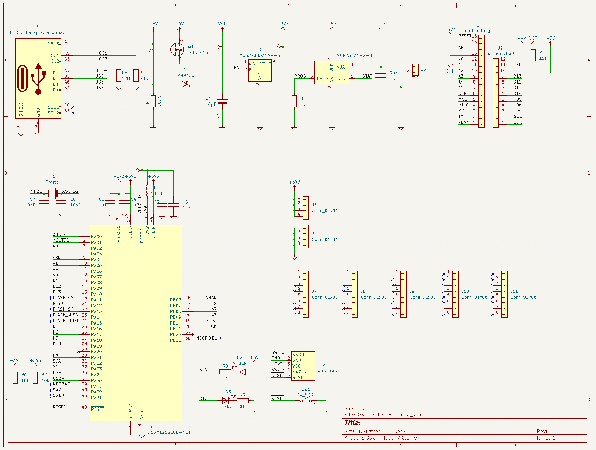
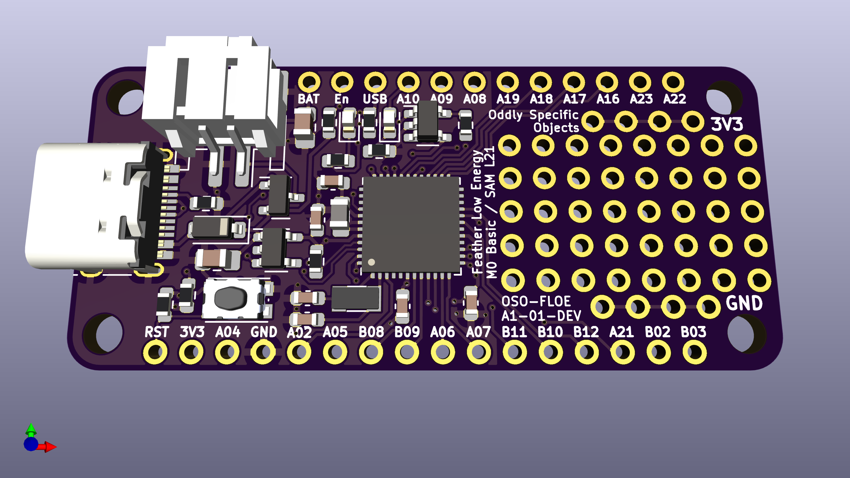
Nevertheless, I'm tossing my hat in the ring for the Op Amp Challenge, and in so doing, I'm open sourcing both the Feather Low Energy board that drives the Feather Op Amp Lab, and the Op Amp Breakout board that moves those pins to a convenient right angle header area at the right side of the wing. Files are attached to the project, but schematics are included below.
I'm releasing these as CC-BY-SA 4.0, which means you're free to make your own Feather Low Energy board, and you're also free to commercialize it and sell it. In fact: Microchip? Adafruit? If you want to make these, I would be thrilled to buy some from you. I run a business making objects — Oddly Specific Objects — but after looking into this, I realize I don't quite have the economy of scale to have these manufactured and still hit a price point that I feel good about. I'll likely keep making these boards for me, just because I have client projects and Oddly Specific gadgets that require a low energy, highly analog Feather.
But if someone wanted to build these, I'd be stoked to buy them rather than having to build them myself.
Anyway, just to recap the whole entry for the Op Amp Challenge:
- The Feather Op Amp Lab is a trio of Feather boards designed to explore the analog domain through the integrated Op Amp peripheral in Microchip's SAM L21 microcontroller. It's comprised of three boards:
- the Feather Low Energy, designed by me and open sourced today.
- a FeatherWing that breaks out the op amp pins.
- and an Adafruit 128x64 OLED Wing
- The Feather Low Energy firmware — open sourced here — displays an interactive UI for op amp configuration, and provides a visualization of the op amps' outputs.
- It's written in a framework called gossamer, which I've also open sourced. This framework aims to be a thin compatibility layer across Microchip's SAM D and SAM L line of microcontrollers
- Gossamer, while a work in progress, is extensively documented, and I hope to use it on more microcontroller projects in the future.
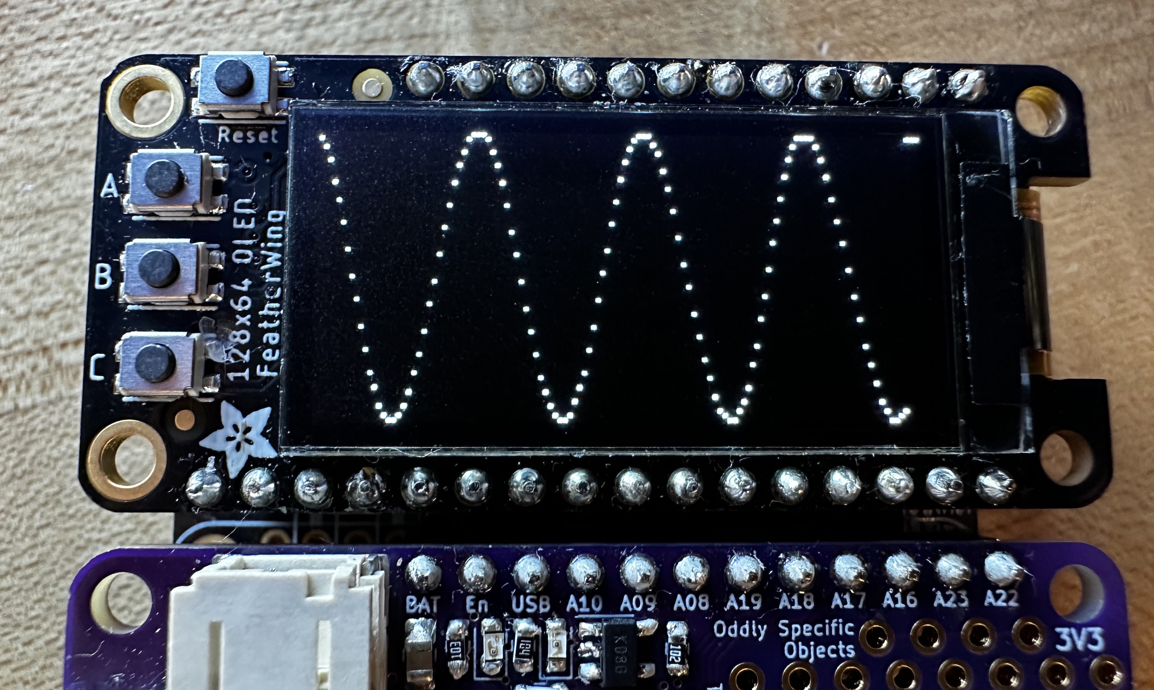
I didn't get to do everything I wanted to do with this project by the deadline, but I'm still calling it a win in my book: this forced me to finally force Feather Low Energy into the world, and building the firmware in gossamer was a fantastic way to stress test what I've been trying to build there; it gave me a chance to add graphics support and OLED drivers to the framework, forced me to add support for a ton of peripherals, and generally just got me stoked about it in a way I hadn't been since I set it aside late last year.
So that's Feather Op Amp Lab. And this:
![]()
![]()
![]()
-
Adding a waveform display to the Feather Op Amp Lab
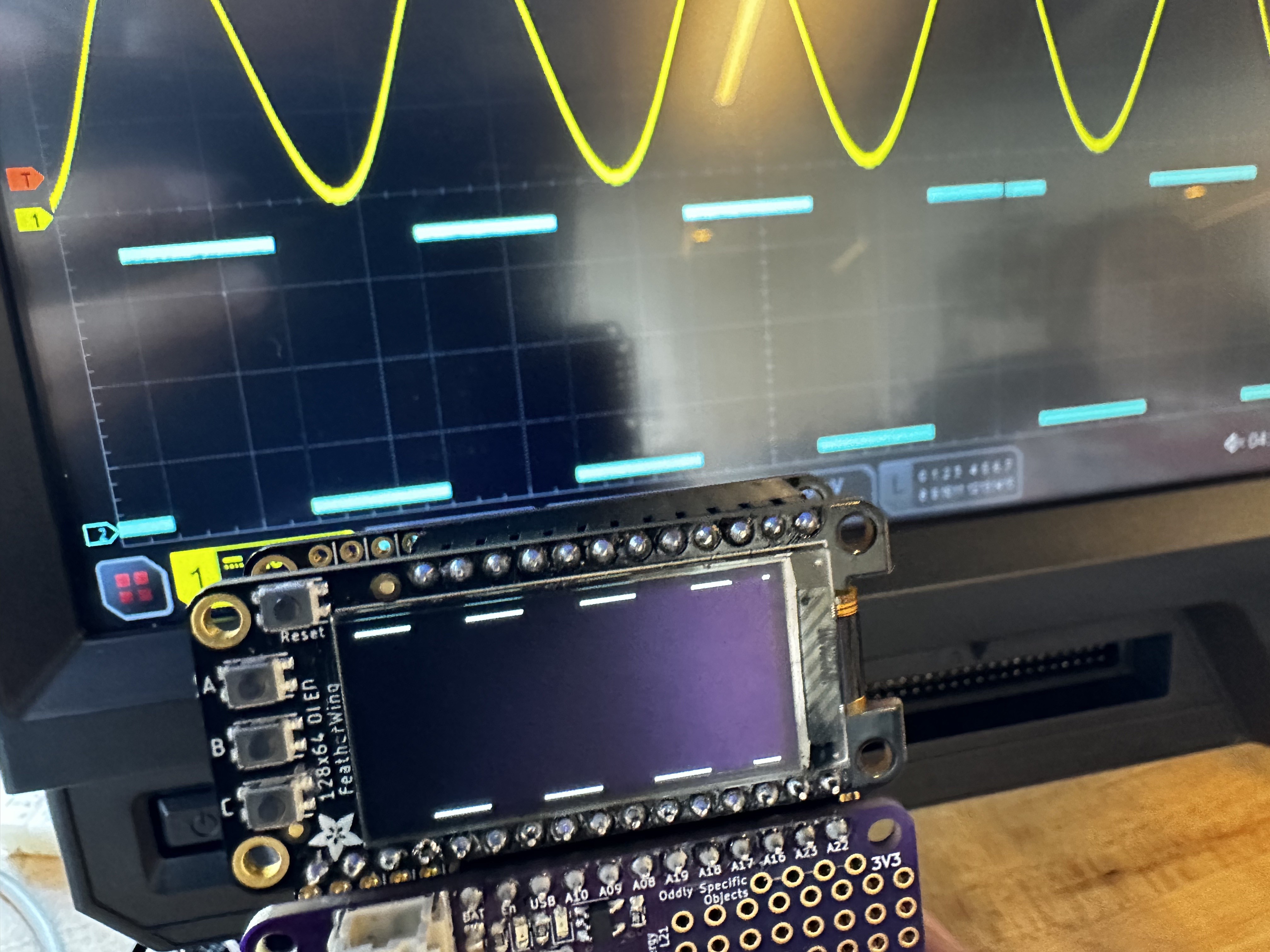
06/01/2023 at 20:53 • 0 commentsThis update works best if you just understand visually what's going on here. I've set up the DAC on my SAM L21 Feather to feed into the first internal op amp. The DAC is outputting a 1 Hz square wave, and I've configured OPAMP0 as a voltage follower, so the output just follows the input. Up until now, I would have had to plug wires into the oscilloscope to visualize the analog waveform coming out of OPAMP0. But then of course, there's already an ADC inside this microcontroller. And a display. So yeah, TL;DR:
![]()
This is cool and all, but then it's not showing us anything we didn't know: if we output a level of 2 volts on the DAC, and OPAMP0 is a voltage follower, and we're measuring the output with an ADC, we're not really doing anything that interesting. We could have just plotted the value we wrote out, right?
To explore the possibilities of the Feather Op Amp Lab, let's configure OPAMP1 to do something with this sine wave. It's the same comparator circuit from last week: OPAMP0 buffers the DAC output, then we put that output on OPAMP1's positive input. The negative input goes to the resistor ladder, in this case configured to divide VCC in half.
![]()
This setup should turn our sine wave into a square wave with a 50% duty cycle. And sure, last week we visualized this on the oscilloscope. But with this week's addition, all we have to do is hold down on button B, and we can see the square wave output right there on the Feather Op Amp Lab's OLED — no external parts required!
![]()
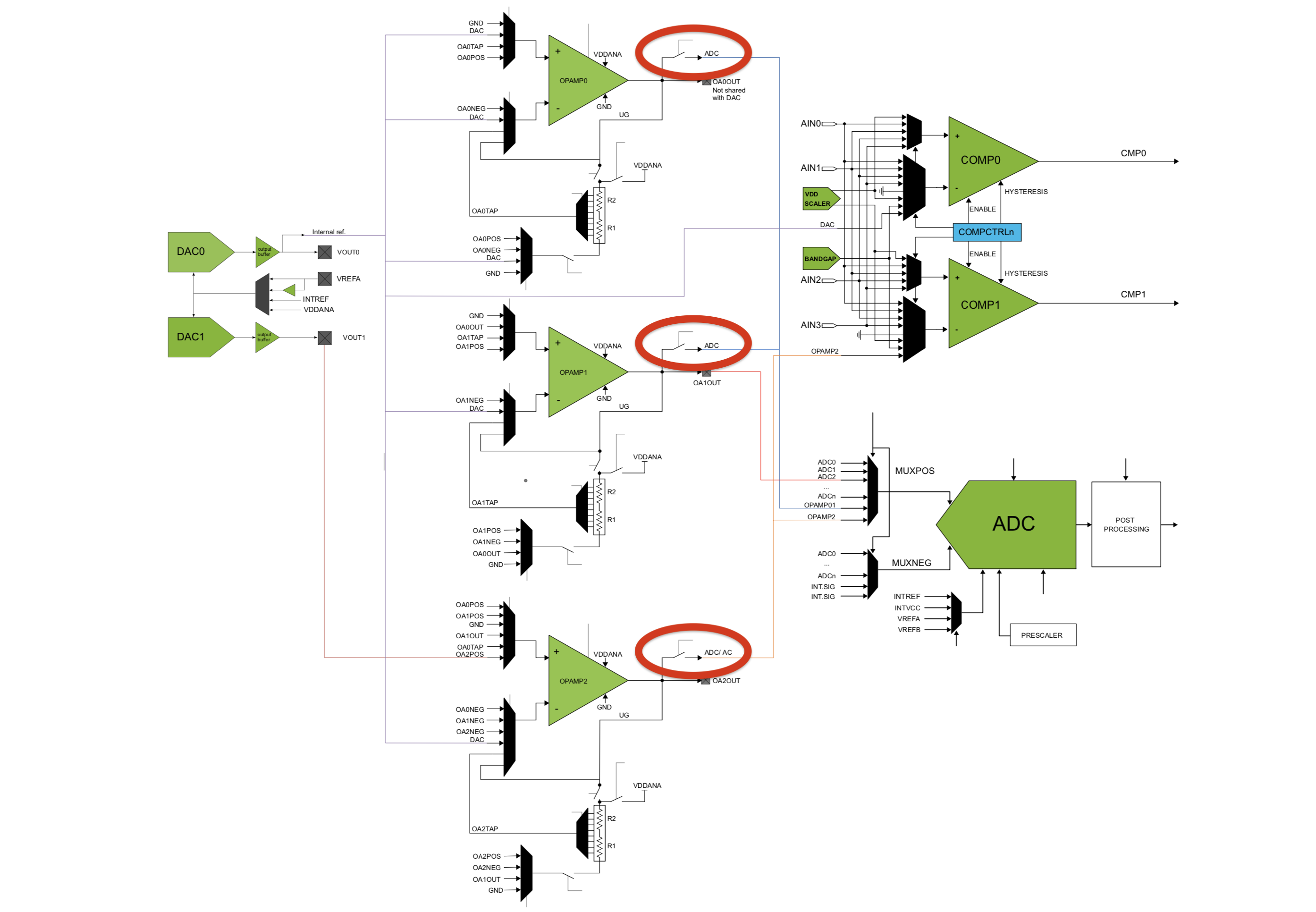
The core of this feature is in one flag that we're able to set in each OPAMP's control register. Called ANAOUT, it controls an internal switch that either connects or disconnects the op amp's analog output to the ADC peripherals inside the microcontroller. It's depicted in a block diagram in the data sheet, titled “Interconnections of Analog Signal Components”:
![]()
In the end, it was a one-line function to add this feature to my op amp driver:
void opamp_set_analog_connection(uint16_t instance, bool connected) {
    OPAMP->OPAMPCTRL[instance].bit.ANAOUT = connected;
}
Again, it feels very simple looking and basic with just this simple comparator circuit, but I think the possibilities at play here are really exciting!
-
Speaking of wings: a FeatherWing breakout from the PCB mill (and the first op amp circuit)
05/26/2023 at 20:18 • 0 commentsOne of the joys of setting this up in Adafruit's Feather ecosystem is that there's a standardized board style for add-ons and breakouts: the FeatherWing. It's like, sure, I could solder to the Feather headers, or even plug into socket header in a wing doubler or tripler. But if, say, I wanted to turn this Feather Op Amp Lab into a microphone amplifier? I could just design a wing that connects the relevant op amp pins to a 1/8" jack, with all the necessary passives right there on the board.
I'm not quite there yet; for the moment, I mostly want to make with the prototyping. But keeping track of which pins are which is a drag; once I decided to put the analog reference pin on AREF and the DACs on A0 and A1, the ordering of the Op Amp pins became a mess:
- OPAMP0_NEG is A0
- OPAMP0_POS is A4
- OPAMP0_OUT is A5
- OAPMP1_POS is A3
- OPAMP1_OUT is A2
- OPAMP2_POS is A1
- OPAMP2_OUT is AREF
Yeah. It's not satisfying at all. What I really want is to have all my op amp pins in a row, arranged in an order that mostly makes sense. So I made a FeatherWing.
![]() ---------- more ----------
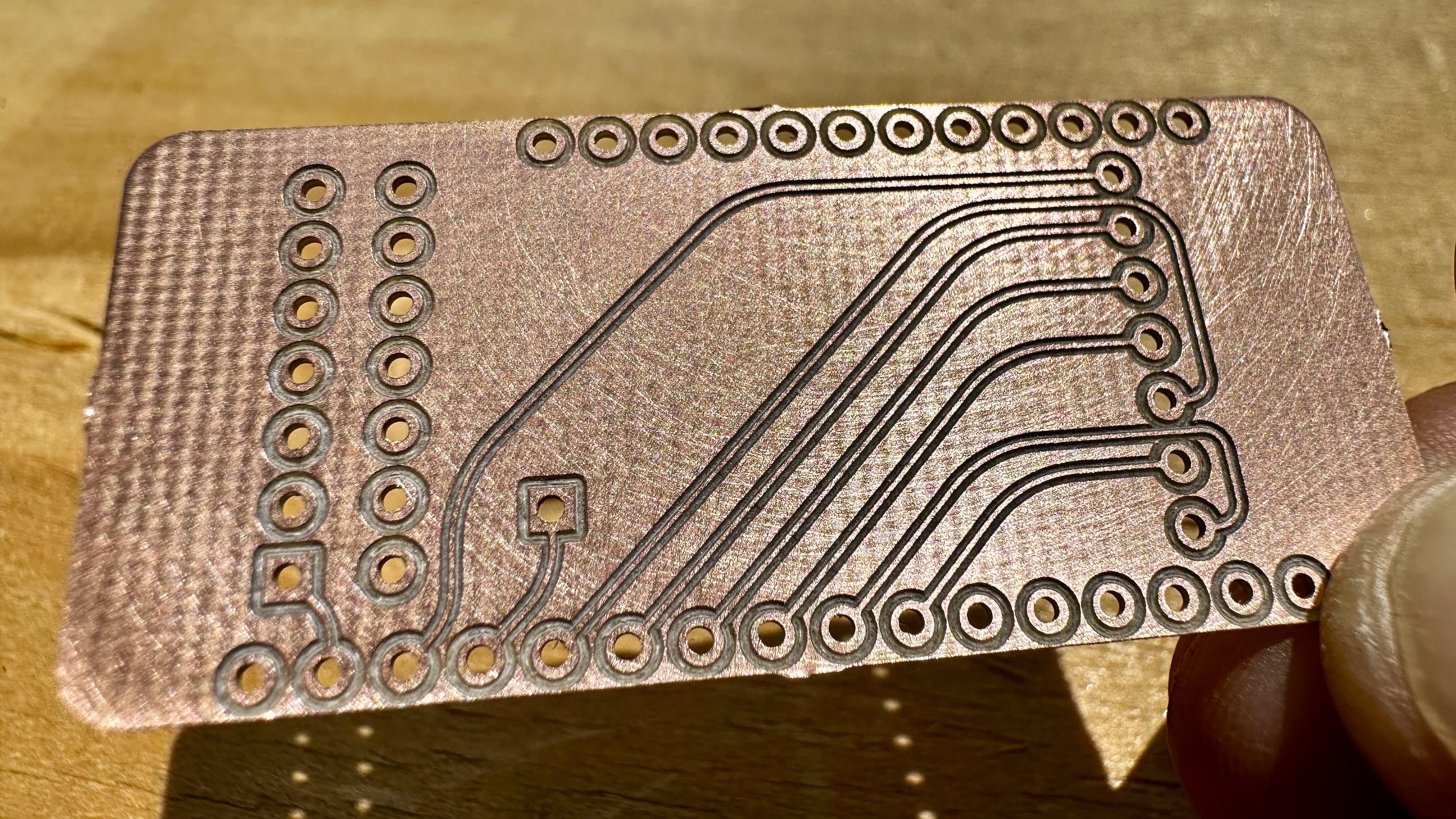
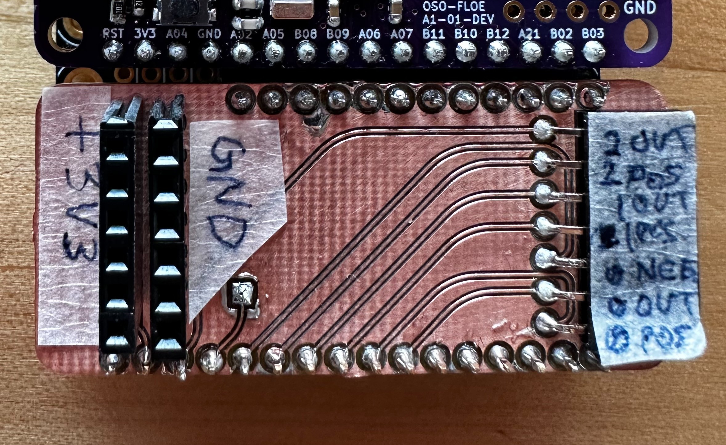
---------- more ----------This FeatherWing is fairly simple: it gives me a row of power and ground pins on the left, and breaks out the analog row on pins on the right. I milled it here at the lab, which is a fascinating process of its own; you start with a piece of copper clad fiberglass, and the PCB mill uses a 0.2 mm bit to carve tiny grooves in the surface — just deep enough to cut through the copper and isolate pads and traces. It looks something like this:
![]()
Once soldered together and labeled, it looks something more like this:
![]()
This wing has taken me through the first experiments with the Feather Op Amp Lab. It makes it super easy to hook the outputs up to an oscilloscope, or to connect the inputs to a breadboard and the maze of passives I need to use to condition analog signals. But really, the first tests are just to make sure that the gadget is doing what it's supposed to do, and this involves building some very simple op amp circuits that don't even need any external components.
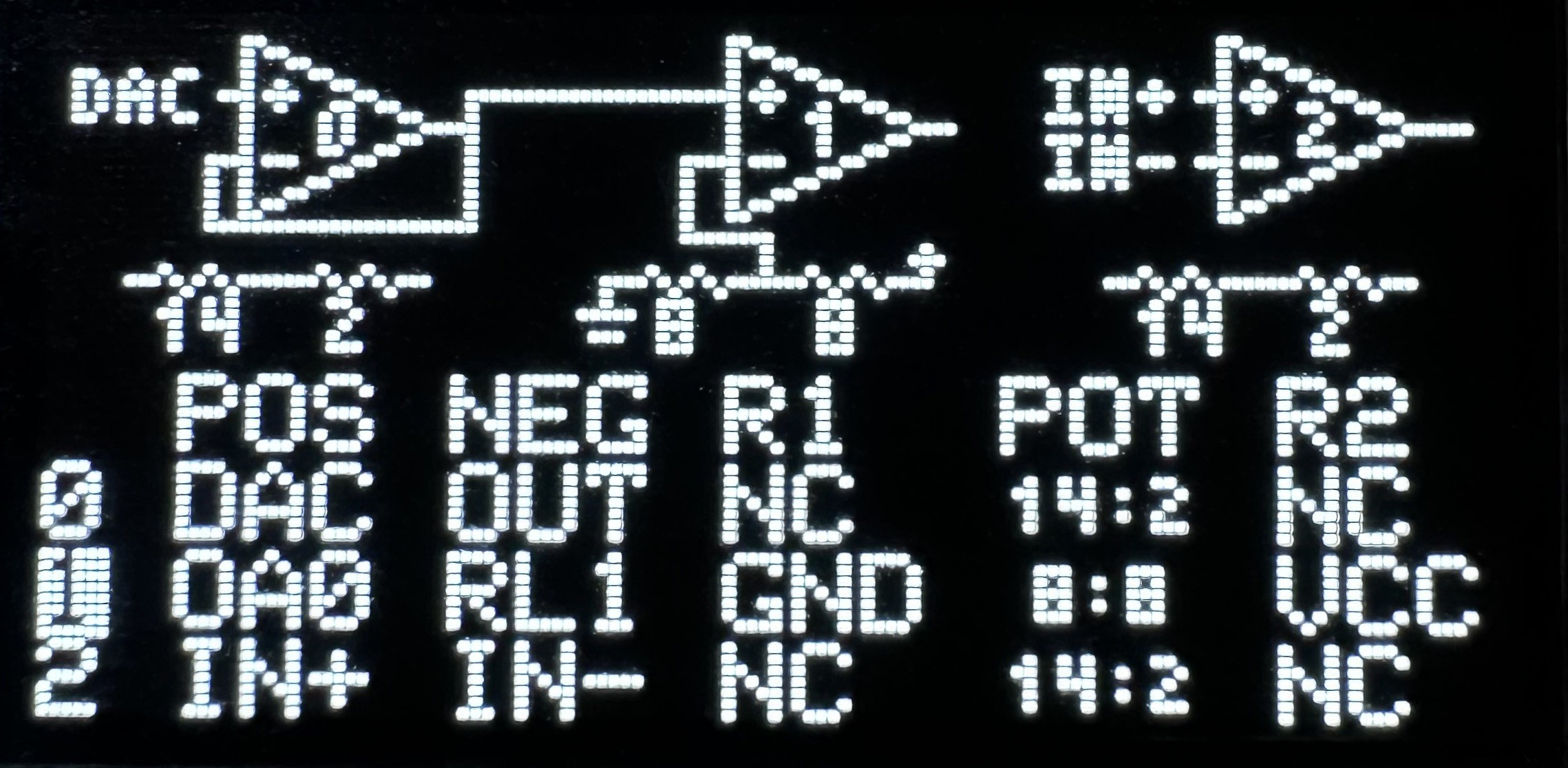
Below is a simple comparator circuit (focus on OPAMP1, in the middle of that diagram in the OLED). I have the SAM L21's DAC configured to output a 100 Hz sine wave, and I've routed its output to OPAMP1's inverting input. The non-inverting input goes to the resistor ladder at the bottom, currently configured to deliver a voltage 1/2 of VCC. This essentially turns our analog sine wave into a square wave, whose duty cycle is dependent on the ratio of R1 and R2 in the associated resistor ladder.
![]()
It's a very simple op amp circuit, to be sure. But it shows the Feather Op Amp Lab working, and it shows that we can build a fully analog circuit using no more silicon than the SAM L21 microcontroller itself. Pretty cool!
-
On gossamer wings we fly
05/23/2023 at 22:39 • 0 commentsThere's a little white lie in the photo that I first posted to the project page. It depicts an OLED screen with a robust UI for operating the Feather Op Amp Lab, but the truth of it is, it's not exactly real. Oh sure, it ran on the L21 Feather, and it output those pixels to the SH1107 OLED, garbled top row and all. But it's a sketch I put together in Arduino that more or less just drew stuff to the screen. Getting the analog stuff to work in Arduinoland was uncharted territory.
To be clear, an Arduino core does exist for the SAM L21. Alas, the mere fact of it having to operate in the Arduino ecosystem means that it makes some choices that I wouldn't necessarily make myself. For a long time those were choices I could live with. But now I'm coming to a point where I need to build my own framework from whole cloth in order to do the things I want to do.
That's where gossamer comes in.
---------- more ----------The gist of gossamer is simple: I work with Microchip's SAM series chips up and down the product line, from the minimalist SAM D11 to the LCD-oriented SAM L22, with a ton of SAM D21 projects as I'm sure you all have too. The gossamer framework aims to unify all of these platforms with a setup that's consistent, simple and appropriate for low power applications. Over the next six months, I expect gossamer to power projects that range from public art to to field data collection.
…and of course the Feather Op Amp Lab.
The Scope
Gossamer targets four chips at this time: the SAM D11, D21, L21 and L22. These chips are all strikingly similar: they all have Cortex M0+ cores and familiar peripherals like ADC's, TCC's and SERCOMs. Alas, a lot of the interfaces to these peripherals have slight differences, and at startup, these chips have subtly different setups.
Gossamer simplifies this by giving us a consistent environment on all four platforms:
- GCLK0, the main system clock and CPU speed, is set to 8 MHz.
- GCLK2 is a low-power, low-accuracy 32 kHz clock sourced from OSCULP32K.
- GCLK3 is a 1024 Hz clock, derived from the most accurate source available.
Peripherals provide sensible defaults, and are automatically clocked from the source that makes the most sense (i.e. RTC from GCLK3, EIC from GCLK2). Gossamer also provides a consistent method for flashing code to a device: running
make && make installbuilds your application and flashes it to a device using a USB bootloader.Finally — the most important part of this log — peripheral drivers are generally thin wrappers around the actual hardware, and provide a consistent way to enable, disable and operate those peripherals.
Peripherals like the OPAMP.
A short and sweet OPAMP driver
The OPAMP peripheral on the SAM L21 is actually astonishingly simple. You enable it, you configure each of the three op amps, and then you turn them on. The actual analog connections are of course more interesting, but for that you can check this excellent application note that describes how to configure the op amps as voltage followers, programmable gain amplifiers, comparators and more. But when it comes to writing code that drives the op amps, this driver does it all in under 100 lines of code.
And as far as making use of the op amp peripheral? This code in our setup function is all we need to create one non-inverting PGA:
void app_setup(void) {
    HAL_GPIO_A4_pmuxen(HAL_GPIO_PMUX_B);
    HAL_GPIO_A5_pmuxen(HAL_GPIO_PMUX_B);
    opamp_init();
    opamp_set_muxpos (0, OPAMP_MUXPOS_POS);
    opamp_set_muxneg(0, OPAMP_MUXNEG_LADDER) ;
    opamp_set_res1mux(0, OPAMP_RES1MUX_GND);
    opamp_set_res2mux(0, OPAMP_RES2MUX_OUT) ;
    opamp_set_potmux(0, OPAMP_POTMUX_RATIO_14_2) ;
    opamp_enable(0);
}
Set the pin mux to make the pins analog, init the op amp and configure it. With this setup, and a single wire coupled to the op amp's positive input, I was able to amplify the millivolt-level 60 Hz hum in my lab to a 3-volt peak-to-peak signal at the op amp's output pin.
When I told my roommate this, he wasn't all that impressed; most of the time, he pointed out, we're trying to get rid of that infernal hum. Still: with this lightweight framework and a few lines of code, we've proved out the analog aspects of this Feather Op Amp Lab, and laid the groundwork for what's to come.
-
Phase One: Pin Assignment
05/19/2023 at 00:05 • 0 commentsWhenever starting a new microcontroller project, one of the first things to do (after, y'know, picking out a microcontroller) is assigning pins to purposes. And on this one, I've had a lot of practice: I first envisioned making a SAM L21 Feather back in 2019, long before I had the skills to design a thing like that (at least to my standards of today).
Anyway, if you clicked the link to that tweet, you'd see a photo of a table from the data sheet, along with my four-year-old notes on what I thought each pin might do. Some of those pin assignments were set in stone; PA24 and PA25, for example, are the only USB-capable pins. Same with PA30 and PA31 for SWCLK and SWDIO. But beyond that, there's a lot of flexibility in how you choose to assign pins to the things you want to do, and especially for a dev board like a Feather, we want to choose to expose pins with the most functionality possible to the end user of our board.
Pin Multiplexing Overview
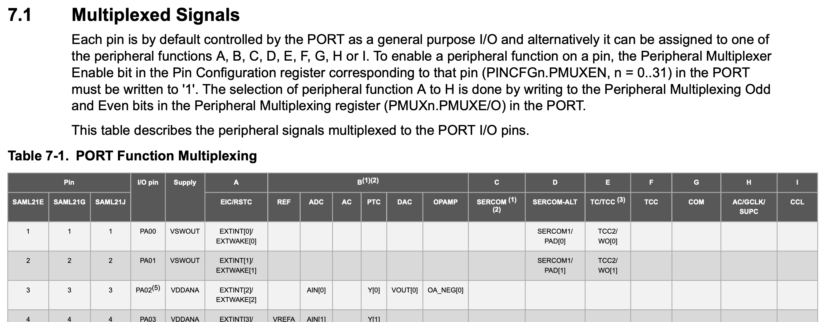
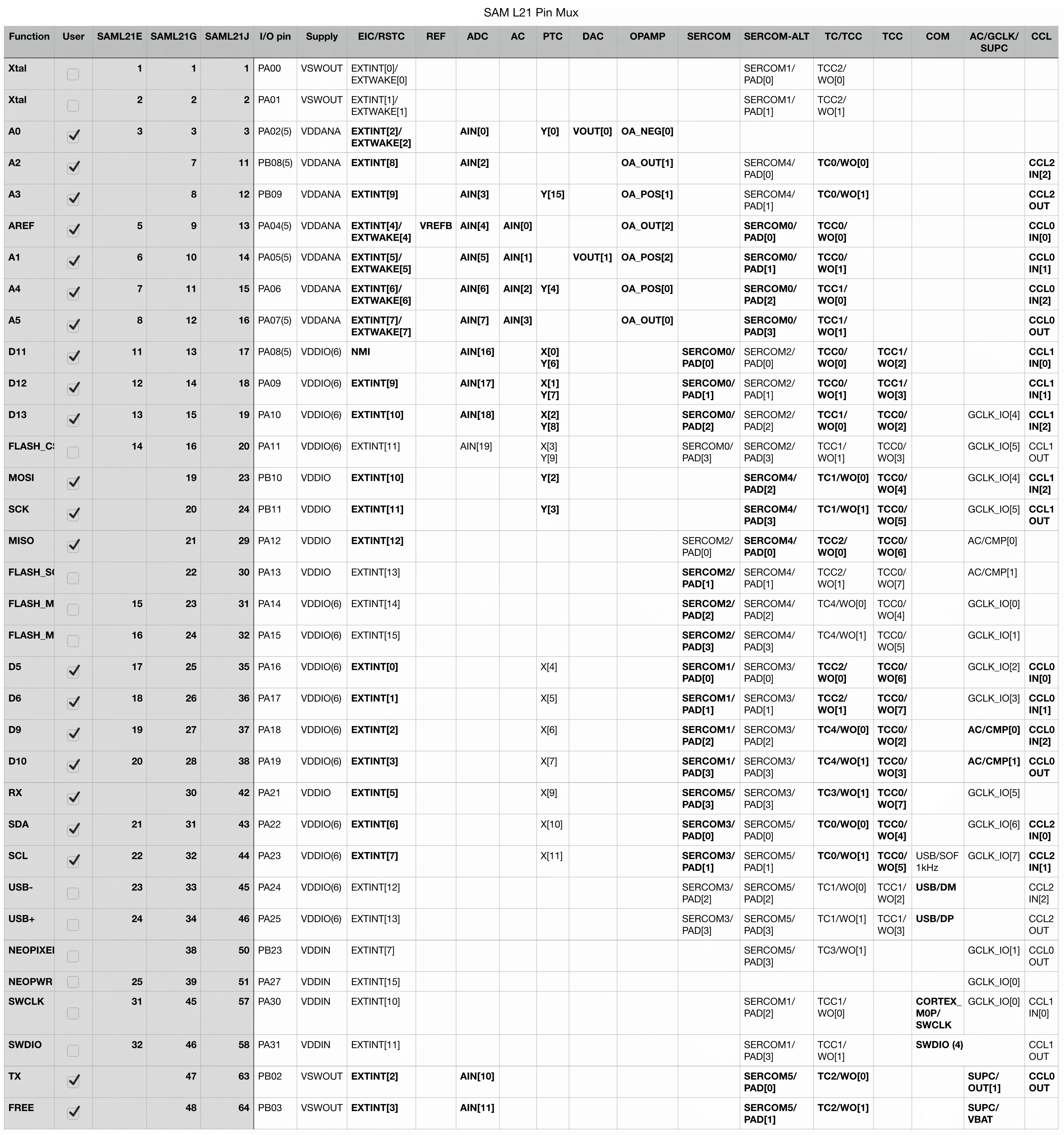
It will not shock you to learn that years later, revisiting this project with more experience and skill, I made different choices. There's a lot to unpack here, but it might be easier to walk through this if we understand roughly what we're trying to do. First off, let's look at the top line of the pin mux table in the SAM L21 data sheet:
![]()
What it's telling us here is that while these pins can be general purpose IO pins, they can also be assigned to different peripheral functions that are described in that top header row. What are those peripherals? Let's walk from left to right, starting with the column named A:
---------- more ----------- Function A connects to the External Interrupt Controller and the Reset Controller, which lets changes to pin state fire interrupts and wake the device from deep sleep.
- Function B is the analog system, which encompasses a bunch of subsystems:
- REF is the Analog Reference system, which lets analog systems make use of an external reference voltage. You might recognize this as the ARef pin on your Feather headers.
- ADC is the Analog to Digital Converter, which lets us measure analog values.
- AC is the Analog Comparator, which lets us passively compare analog values without constantly measuring them.
- PTC is the Peripheral Touch Controller, which lets us natively respond to touch inputs.
- DAC is the Digital to Analog Converter; the reverse of the ADC, it lets us output analog signals.
- And finally OPAMP is the Operational Amplifier Controller, which is kind of the name of the game here!
- Functions C and D are the Serial Communication Interfaces; these are versatile, and speak familiar protocols like SPI, I2C and UART.
- Functions E and F are the Timer Counter and Timer Counter for Control, versatile timer peripherals that can output PWM waveforms suitable for everything from beeping a buzzer to controlling a servo.
- Function G is for specialized communications; in our case, it's just the USB Interface and the Serial Wire Debug Interface.
- Function H is a hodgepodge; it has the outputs from the Analog Comparator, as well as some Generic Clock Controller pins. It also has a couple of Supply Controller pins; that system is way at the bottom of everything, literally supplying our chip with electrical power. More on that later!
- Finally, function I is the Configurable Custom Logic, which is sort of like a mini-FPGA with lookup tables and logic gates. I haven't used this much, but I want to in the future!
Goals
PHEW! That's a lot! Lest we get overwhelmed, let's take a step back and figure out what our goals are:
- I'm doing this for the Op Amp Challenge, so I want to break out all of the op amp pins, naturally.
- I need to connect the analog reference system to the Feather's ARef pin.
- I need the standard Feather features: USB, I2C, SPI and UART.
- I'd like to reserve some pins for future use: a second SPI bus for a SPI Flash chip, and a Neopixel to make it an "Express" style board.
- Beyond that, my only goal is to break out as much functionality as I can; if later I decide I want to use, say, the Analog Comparator, I want to make sure that those Analog Comparator pins are broken out.
Picking Pins for One Subsystem
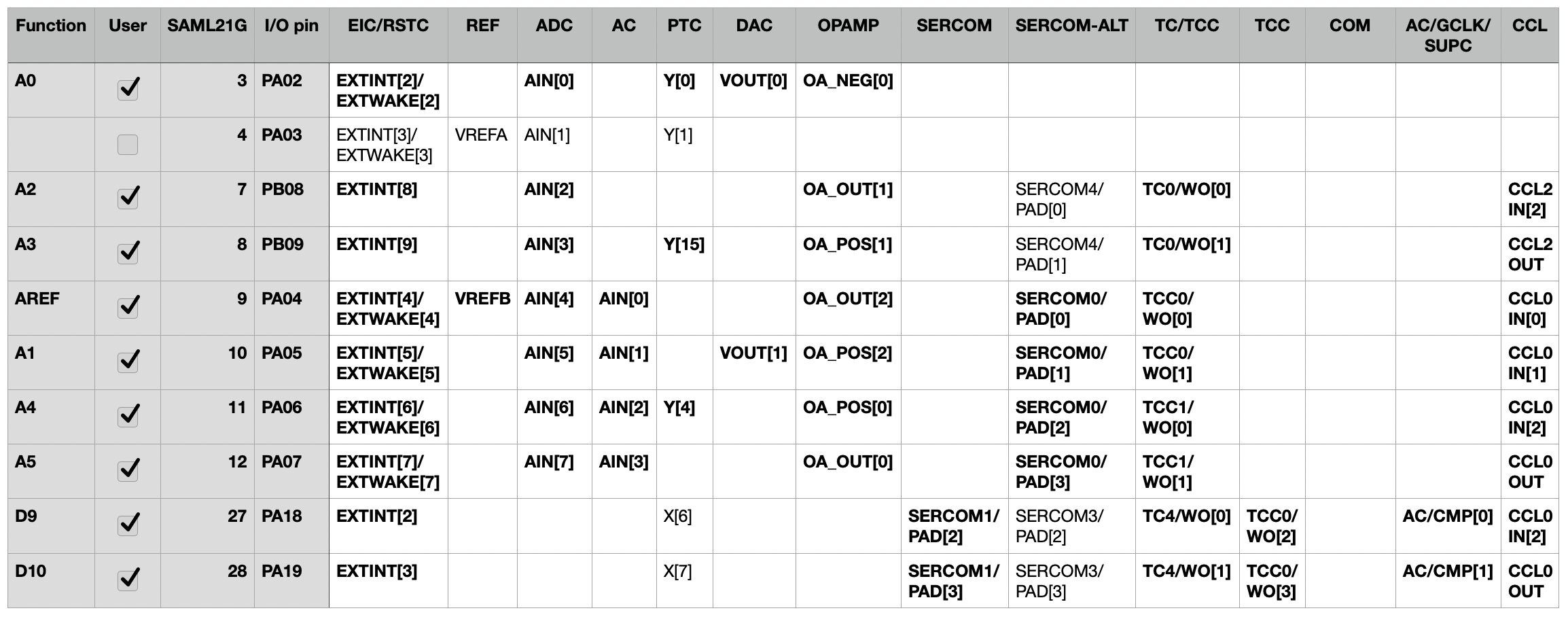
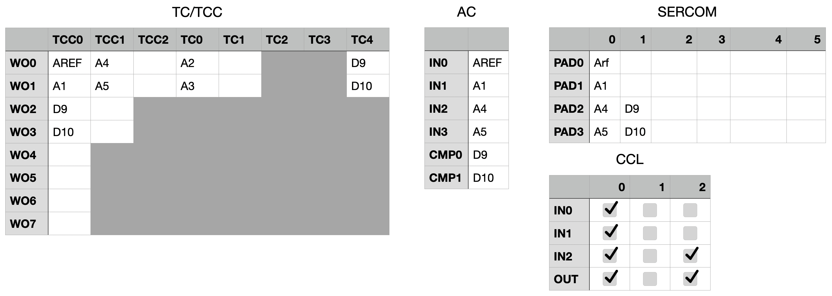
In fact, let's take a look at the analog system now. Here I'm highlighting just the pins related to the ADC, AC, DAC, OPAMP and REF systems:
![]()
There are two pin numbers that matter here: Function is the pin I'm assigning them to on the Feather headers. I/O pin is the pin as named in the underlying firmware. And the functions on the right are the different things we can use them for. So, off to the far left, we can connect, say, I/O pin PA02 — the DAC's VOUT[0] — to pin A0 on the Feather header. It feels right that DACs should be on the first analog pins available.
For the REF system, we have two options: VREFA on PA03, and VREFB on PA04. But looking closer, PA03 doesn't do that much for us; it has a PTC channel, but other than that, it's kind of a slouch. Instead, I've claimed PA04 for the cause, because it has more alternate uses: we can use it as voltage reference B, but it also works with the analog comparator, op amp #2, a SERCOM peripheral, the TCC for PWM, or as an input to the CCL peripheral.
On and on we go; PA05's VOUT[1] becomes the second DAC on A1, and then A2-A4 get the remaining opamp pins. With that, we've successfully achieved goals 1 and 2 — and we're on our way to #5! Given all the alternative functions of these pins, we've already broken out two and a half SERCOMs, eight PWM outputs and six pins in the CCL!
![]()
And on and on...
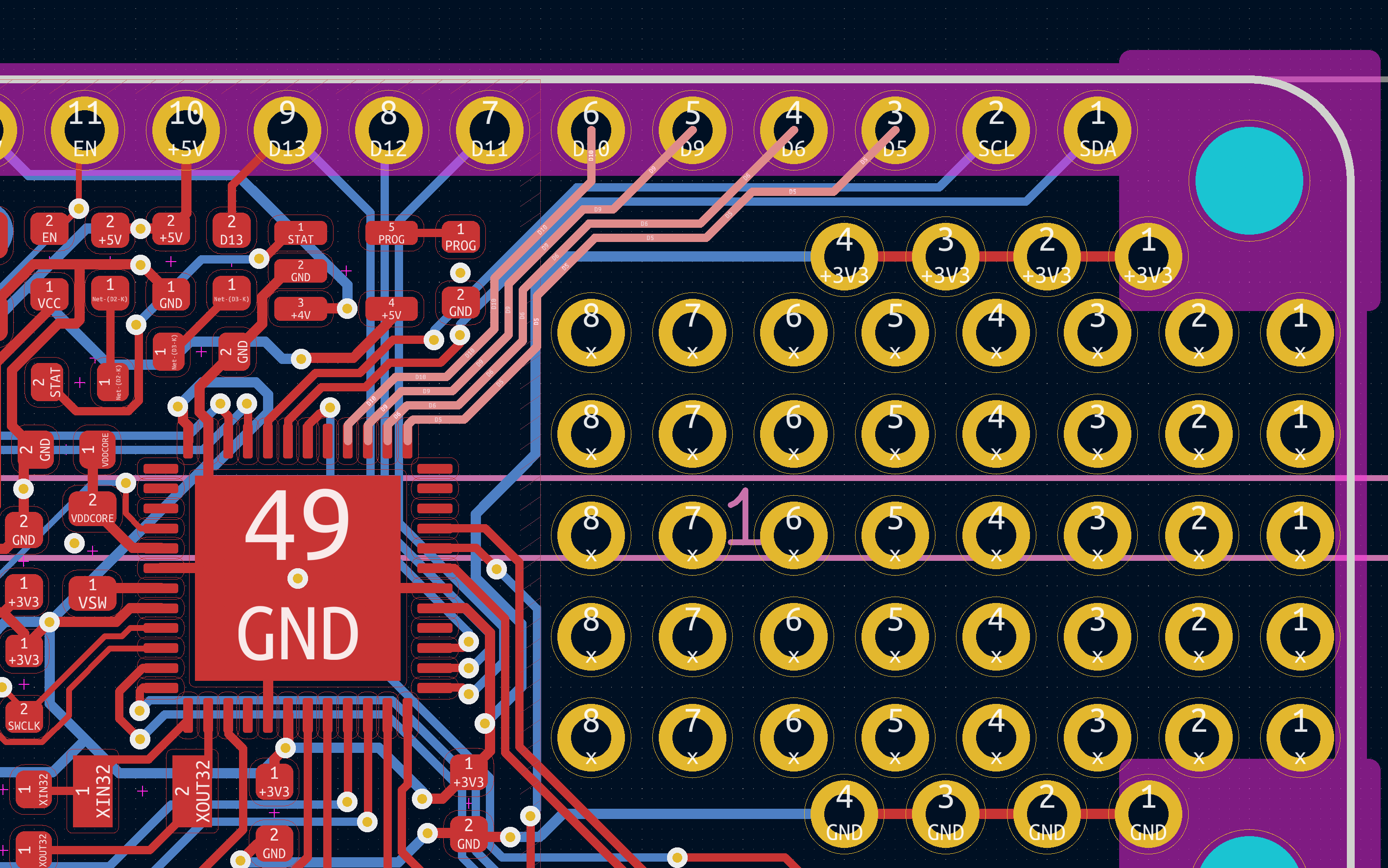
I could go on and on about this process, but let's do the rest in broad strokes: For goal #3, we need to find three free SERCOMs (two pins each for I2C and UART, and three for the SPI bus). Goal #4 is much the same: four pins for a Flash SPI bus, and two for Neopixel and Neopixel power. Chewing through the list, it sometimes feels like solving a crossword puzzle. Other times, it feels like solving a maze; in the screenshot below, once I considered routing, it felt only natural that pins 5, 6, 9 and 10 would connect to the top right of the chip; there really weren't many other options.
![]()
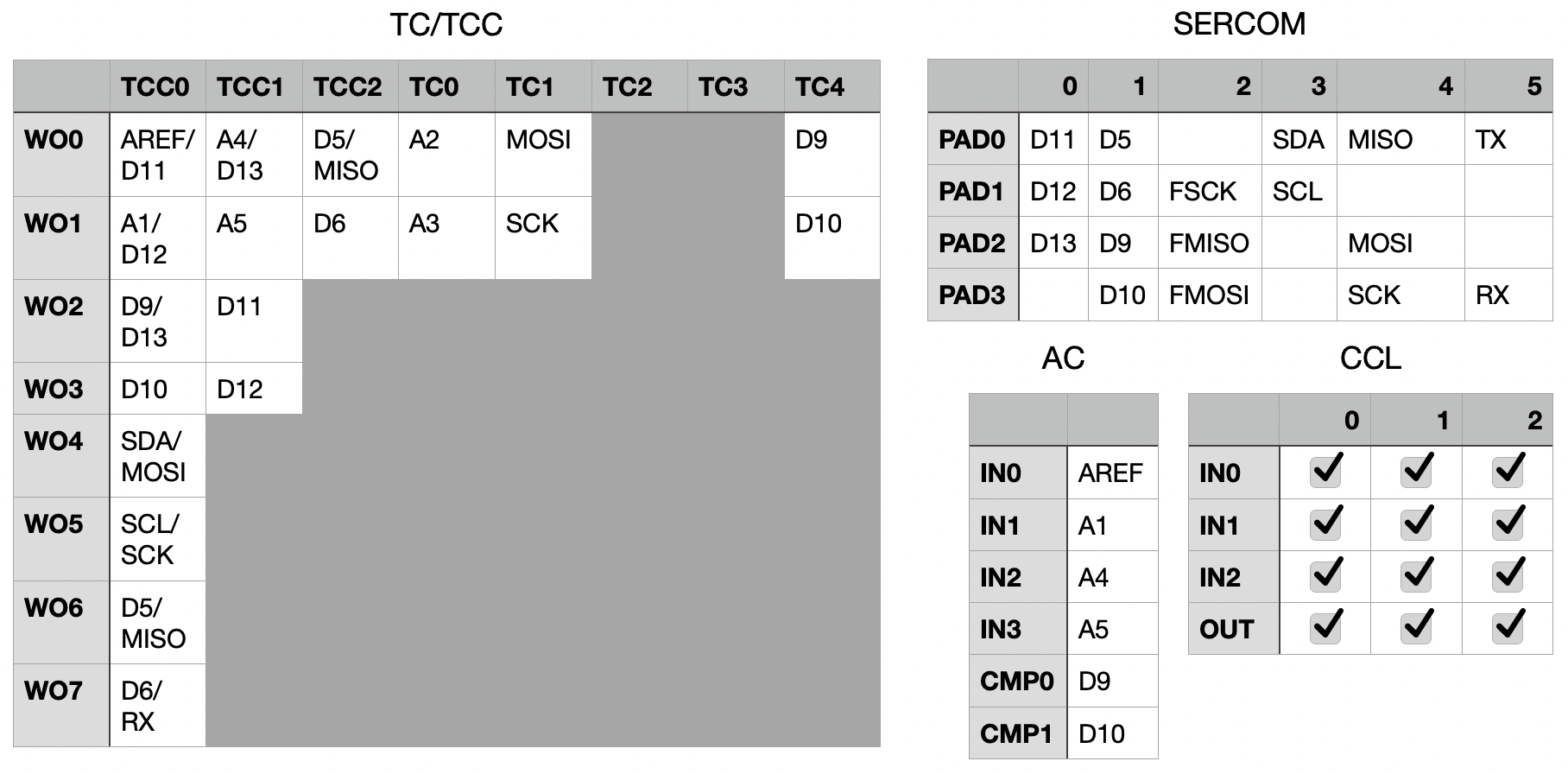
Final Answer
To make a long story, well, not short, but less long: here in all its glory is the pin mux for the new Feather Low Energy. The gist:
- External 32 kHz crystal for timekeeping
- All op amp pins on A0-A5 (and ARef)
- DACs on A0 and A1
- AC inputs on ARef, A1, A4 and A5
- PWM on all regular Feather pins except A0:
- All eight pins of TCC0 for NeoPXL8 goodness
- All four pins of TCC1
- Both pins of TCC2, TC0, TC1 and TC4
- SERCOMs 3, 4 and 5 dedicated to I2C, SPI and UART
- Extra SERCOMs 0 and 1 available on the top row
- SERCOM2 reserved for a Flash chip
- All CCL inputs and outputs available on pins
- Supply controller's low power output is broken out on the TX pin
- Supply controller's battery backup input is broken out on the extra "free" Feather pin at the bottom right
![]()
I think this is the most optimized possible pin selection for a SAM L21 Feather board. I think it will serve me well in the Op Amp Challenge, and I foresee it making its way in to many more projects in the future.
![]()
Feather Op Amp Lab
A custom Feather with SAM L21 microcontroller, paired with wings that let us interactively explore its integrated op amp peripheral.