RobsonCouto
-
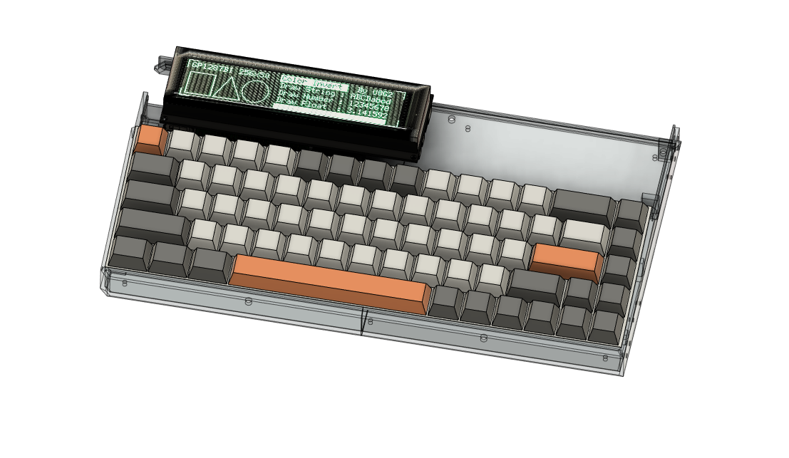
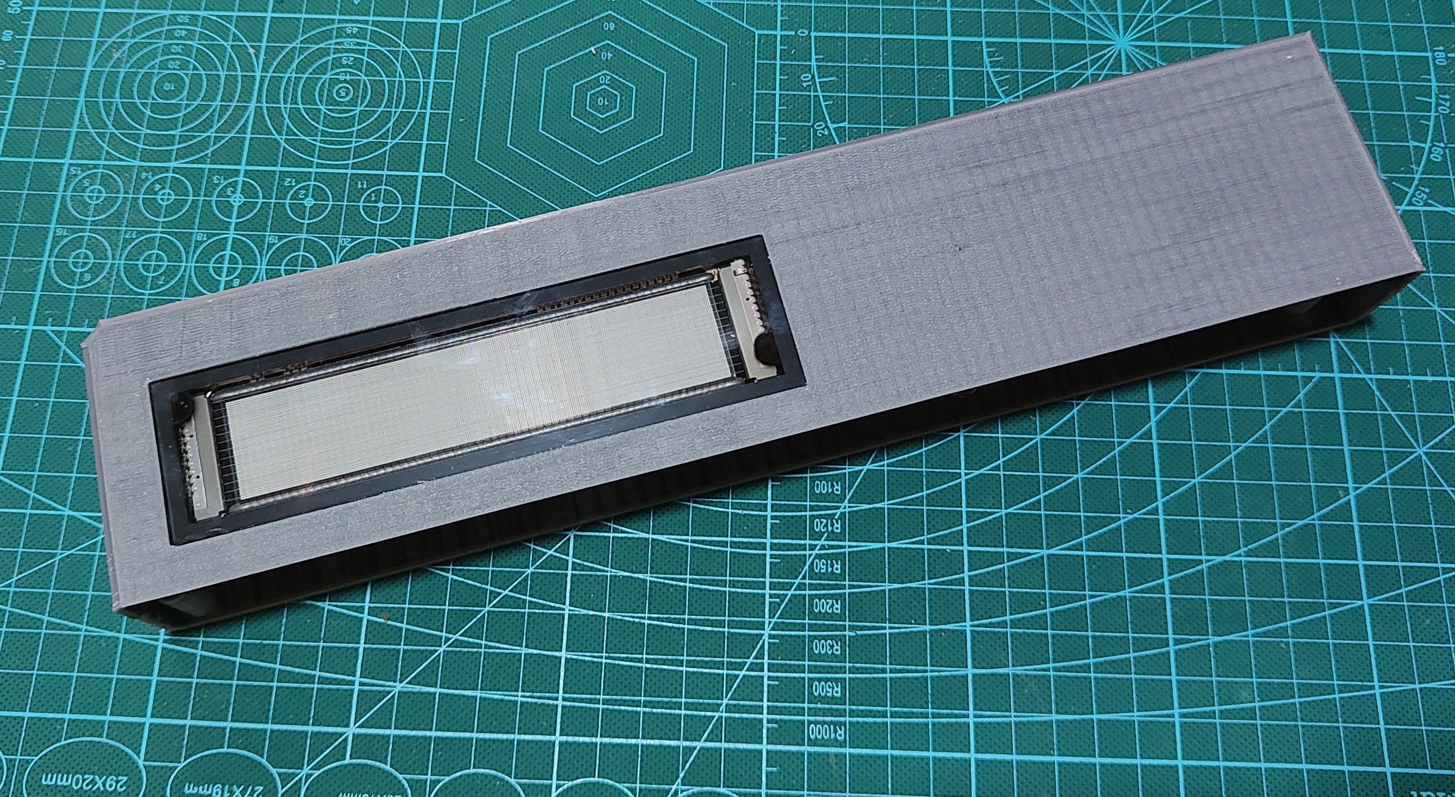
Entry 0x16 - VFD display working. Sort of
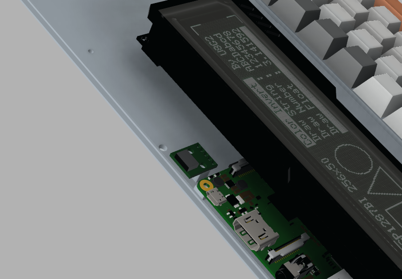
08/24/2023 at 18:37 • 2 commentsI haven't had the time to work on the framebuffer driver, since I spent most of the time modelling the shell. Still, I could not continue without taking some nice pictures with the display working. So I coded a little script to use the interface exposed at /dev/spidev and initialise and write to the display.
![]()
Which worked fine. I just had to manually reverse the bytes before writing, since spi0 does not have a LSB option. Apart from that I just did the init sequence from the datasheet and got it working in no time.
Anyways. Like I said, my plan is to code a kernel space driver to be used by linux. The good thing is now at least I have a good setup since everything is wired up and held firmly in place. I can focus more on the software.
The following snippet is part of the display test script. The whole script is in the project files.GP1294AI_CMD_RESET = 0xAA GP1294AI_CMD_FRAME_SYNC = 0x08 GP1294AI_CMD_BRIGHTNESS = 0xA0 GP1294AI_CMD_DISPLAY_MODE = 0x80 GP1294AI_CMD_WRITE_GRAM = 0xF0 GP1294AI_CMD_DISPLAY_OFFSET = 0xC0 GP1294AI_CMD_VFD_MODE = 0xCC GP1294AI_CMD_OSC_SETTING = 0x78 GP1294AI_CMD_EXIT_STANDBY = 0x6D GP1294AI_CMD_ENTER_STANDBY = 0x61 GP1294AI_MAX_FREQ = 4167000 GP1294AI_DEFAULT_BRIGHTNESS = 0x0028 cmd_reset = [GP1294AI_CMD_RESET] cmd_init = [GP1294AI_CMD_VFD_MODE, 0x01, 0x01F, 0x00, 0xFF, 0x2F, 0x00, 0x20] cmd_brightness = [GP1294AI_CMD_BRIGHTNESS, GP1294AI_DEFAULT_BRIGHTNESS & 0xFF, (GP1294AI_DEFAULT_BRIGHTNESS >> 8) & 0xFF] cmd_offset = [GP1294AI_CMD_DISPLAY_OFFSET, 0x00, 0x00] cmd_mode = [GP1294AI_CMD_DISPLAY_MODE, 0x00] cmd_init_osc = [GP1294AI_CMD_OSC_SETTING, 0x08] # We only have SPI bus 0 available to us on the Pi bus = 0 #Device is the chip select pin. Set to 0 or 1, depending on the connections device = 0 # Enable SPI spi = spidev.SpiDev() # Open a connection to a specific bus and device (chip select pin) spi.open(bus, device) # Set SPI speed and mode spi.max_speed_hz = 500000 spi.mode = 3 def reverse(array): for index, value in enumerate(array): array[index] = int('{:08b}'.format(value)[::-1], 2) return array def spi_transfer(array): spi.xfer2(reverse(array)) def clear(): empty_frame = [0] * (256*8) payload = [0xF0, 0, 0, 48] + empty_frame print(len(payload)) spi_transfer(payload) def init(): spi_transfer(cmd_reset) spi_transfer(cmd_init) spi_transfer(cmd_brightness) clear() time.sleep(0.02) spi_transfer(cmd_offset) spi_transfer(cmd_mode) spi_transfer(cmd_init_osc) -
Entry 0x15 - Wiring
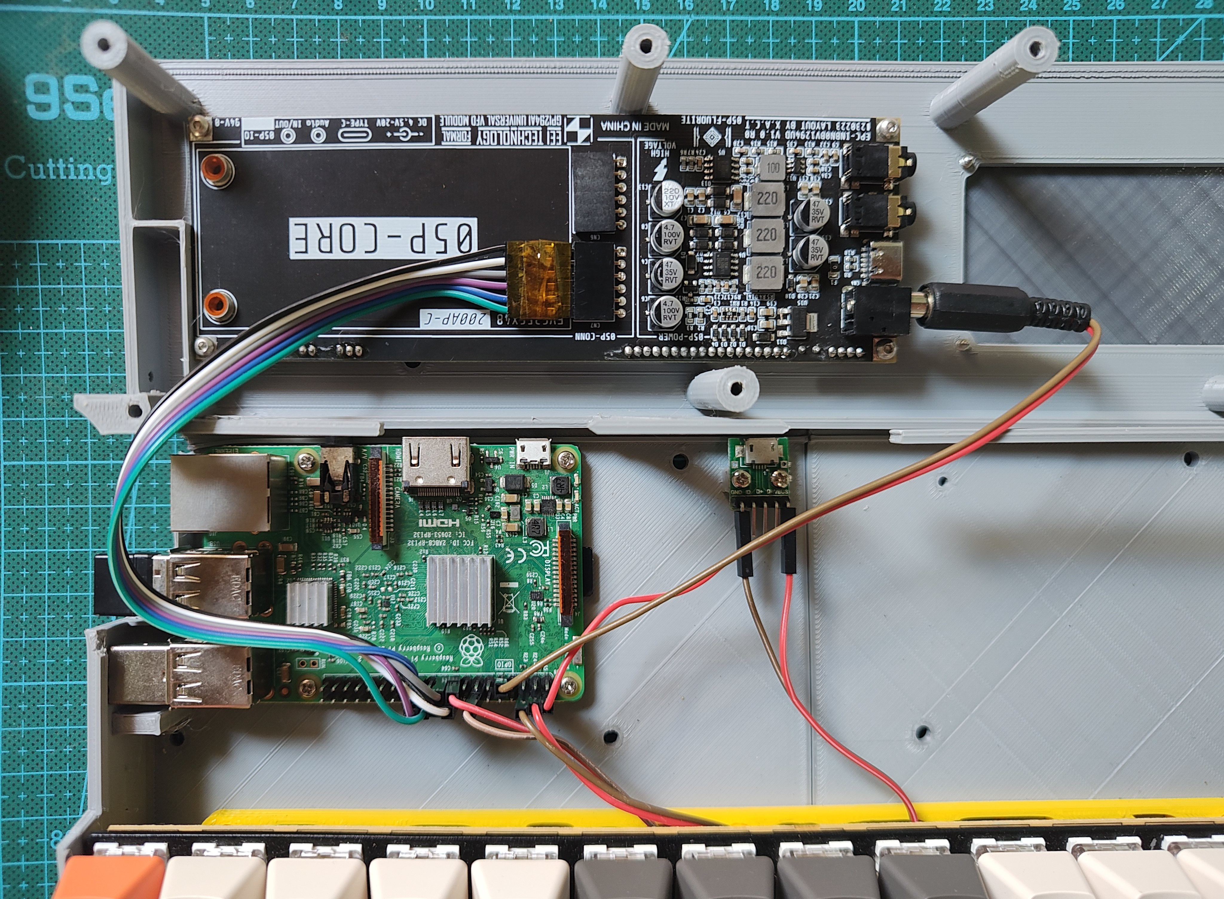
08/24/2023 at 12:28 • 0 commentsWiring (at this moment) is quite simple:
![]()
I added a USB breakout which I use as input. It is connected to the raspberry pi and to the VFD display. The display supposedly takes in a lot of power, so I'm using a beefy usb charger, without problems. There's is no battery yet, but the space for it is reserved at the left, just haven't got the time to think about that yet and buy something that suits the project.
![]()
The VFD display is hooked up to the raspberry pi via the SPI interface. Meanwhile, the keyboard is powered by the 3.3 source on the raspberry pi.
Besides the battery, I also want to add a few LEDs to highlight some details and glow in the same color as the display. Furthermore, two of the usb ports are reserved for the deck and I have a little USB hub to put inside the case to expand communications.
![]()
Also, don't forget my original plan is to use this for logical IO and serial, so there's some space and cutouts on the back for that that too.
-
Entry 0x14 - Surface detailing
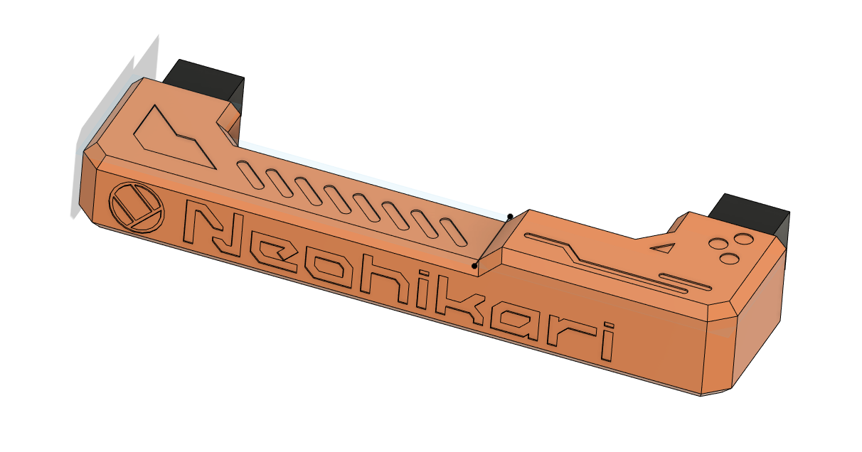
08/19/2023 at 19:20 • 0 commentsLike I said in the previous logs. i'm trying to add detail to the surfaces, something that is completely new to me. The handle will some details "debossed" directly on the surfaces.
I've watched some videos on detailing, although not about cyberdecks, but still really useful tips for making props and models look hi-tech.
I do recommend this video by CUt Transform Glue, in which they scratchbuild a beautiful spaceship. The tip I got from this video is to try to overdo when adding details. As much I would like to cover the whole deck with details, I would not have enough time, so for now I'm focusing on visible surfaces.I also watched some videos by the great Adam Savage. You may know him from myth-busters, but his Youtube channel is a pleasure to watch. There's tons of videos, but I'm gonna leave here just this short one about the universal greeblie.
-
Entry 0x13 - Virtual to physical
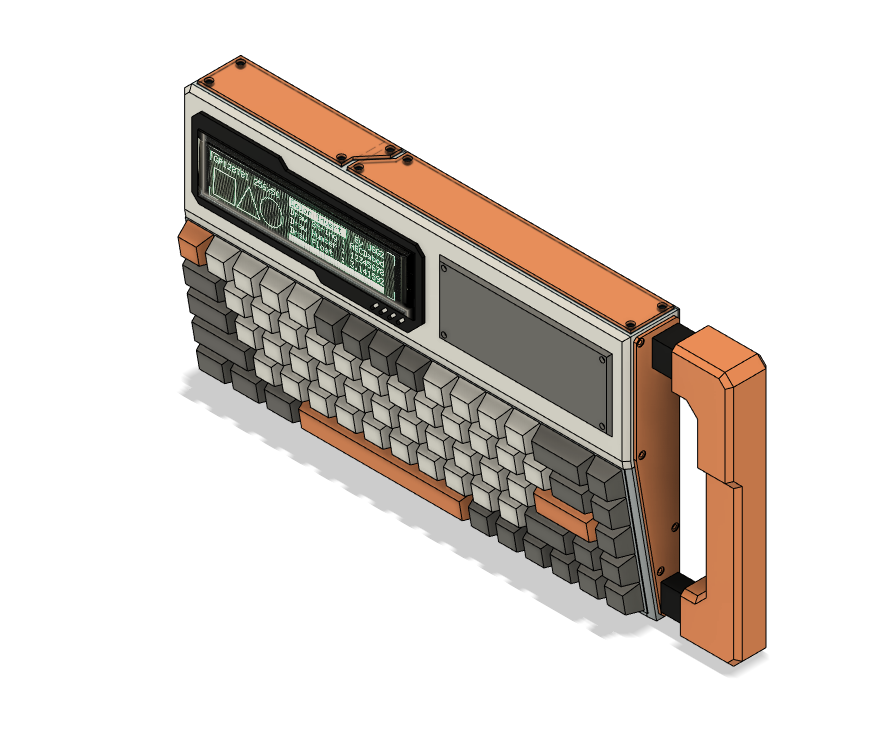
08/19/2023 at 15:19 • 0 commentsI'm a bit frustrated for not meeting up the (short) contest deadline despite putting most of my free time into this. Still, it's a little rewarding to finally see my design coming to the real word part by part.
![]()
After printing every part I always find something to fix. Either some holes are too loose of some part is too weak or too thin or I put a screw where I should not. It's okay, since I'm still leaning.
While parts are printing I give attention to other things, like adding detail to the panels.
![]()
-
Entry 0x12 - Keeping On
08/16/2023 at 13:00 • 0 commentsI guess the deadline to submit builds to the contest is over, but I can keep building while the projects are being judged. At this point my deck is still mostly a 3d file on my computer and a bunch of parts.
This morning I went to look in my stuff for a USB C breakout that I bought for this project and after some checking on my orders history I realised that I in fact did not buy the breakout. I found a micro USB breakout, that so that will do for now. I added the breakout support to the shell and gonna try printing the bottom shell again later today.
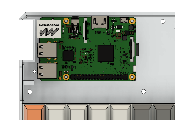
I also took the opportunity to touch up the ethernet and USB ports cutout from the raspberry pi on the side of the deck and I'm so proud of that :)
![]()
As I said, gonna try printing again. Wish me luck!
-
Entry 0x11 - Disaster
08/14/2023 at 11:00 • 4 commentsQuick update. After a 16h print, I broke the new part in the first 5 minutes. I'm not very experienced in 3d print and now I believe printing on its side made the case too weak. Also, the shell warped a lot, despite being PLA.
![]()
Because of this, I tried to remodel the shell to fit in my printer (300x300 mm), which bugged my designs a little. Kind of a setback.I may have to switch colors and I believe I have enough white to print the case. White with orange accents looks cool in my opinion.
![]()
-
Entry 0x10 - Bottom part of the shell
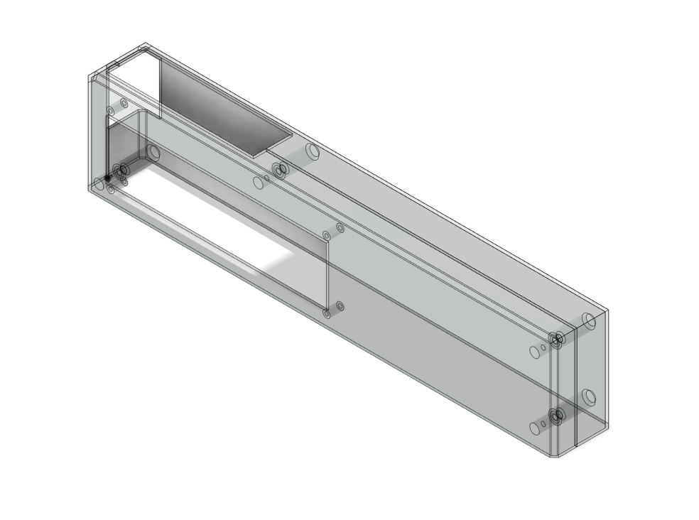
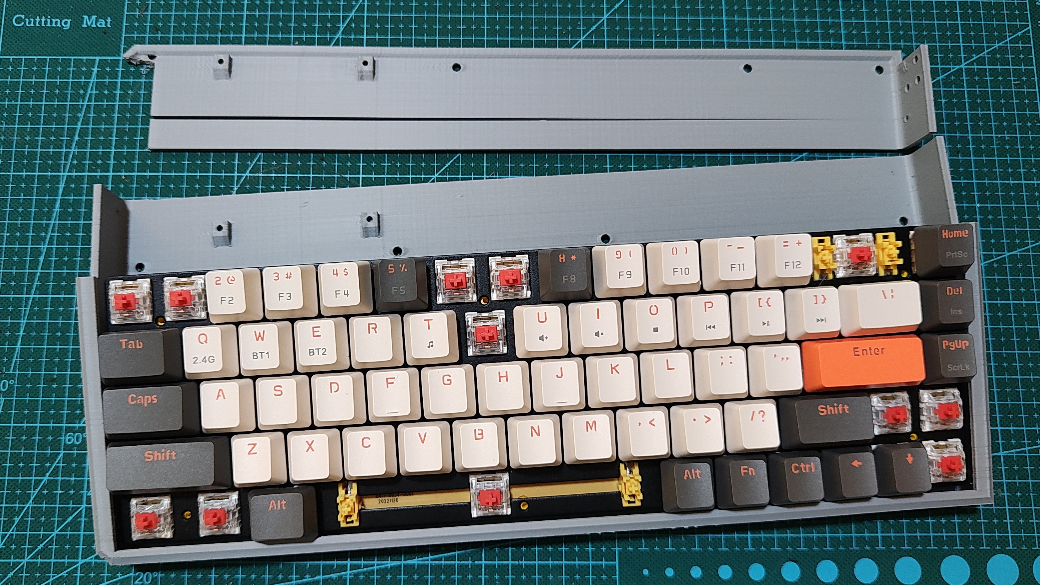
08/13/2023 at 14:13 • 0 commentsI think I now have something I'm happy with, that is, structurally. I cut the shell in two parts that I think will print well. I started printing the bottom part, which was printing overnight and is still going. I turned off supports so now I'm praying the upper left side does not get too messed up.
![]()
The holes on the back face are for mounting the keyboard support and and the top part. Speaking of which:
![]()
I mostly going for looks with this project, and aesthetically I'm too far from what I wanted. I think I said in a previous log that I would like to add lots of detail to the surface, and since I'm running against time here, my idea was to transfer the details to panels which I will attach to the main body.
That way I can make quick prototypes and tweak the design without printing everything out again. Next log I will tell how the printing went, there's still a few good hours till it's finished.
-
Entry 0x0F - Quick Updates
08/10/2023 at 23:19 • 0 commentsSome major events happened in my personal life this week and I had very little time to spend on the project. Last time I worked on this, I got a little frustrated with truing to bind the Raspberry PI spi 0 or 1 and respective chip select pin to my driver, and arrived at the conclusion that I need to study more. A brute force approach does not work here.
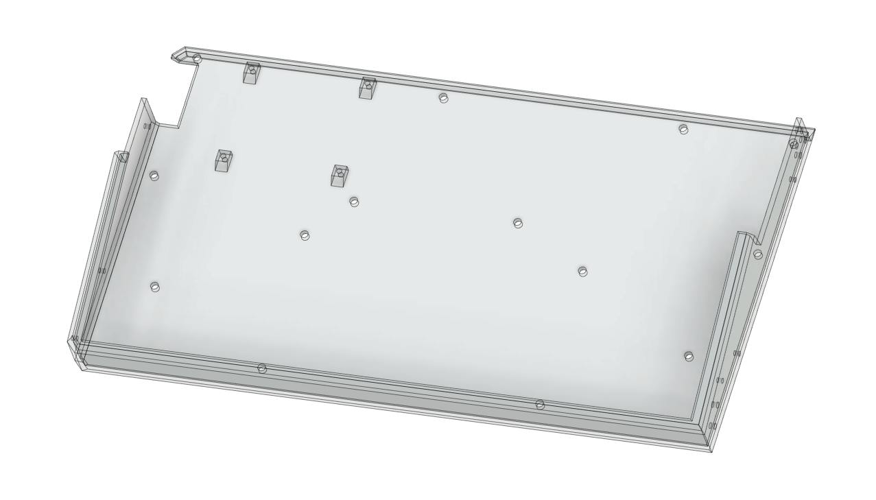
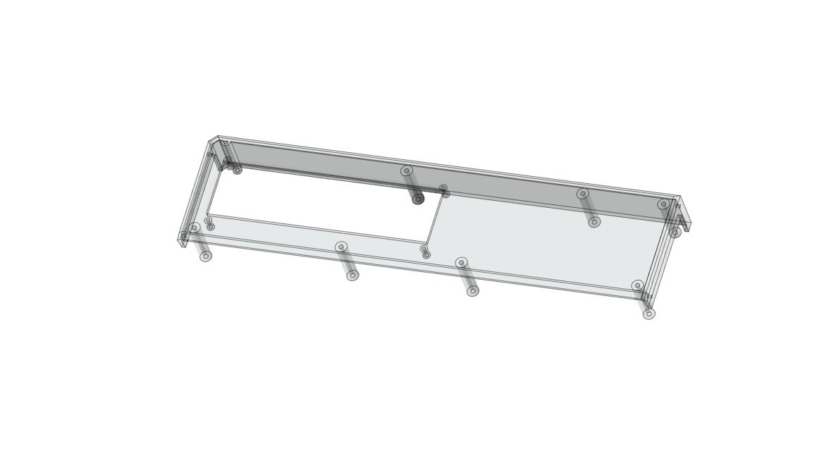
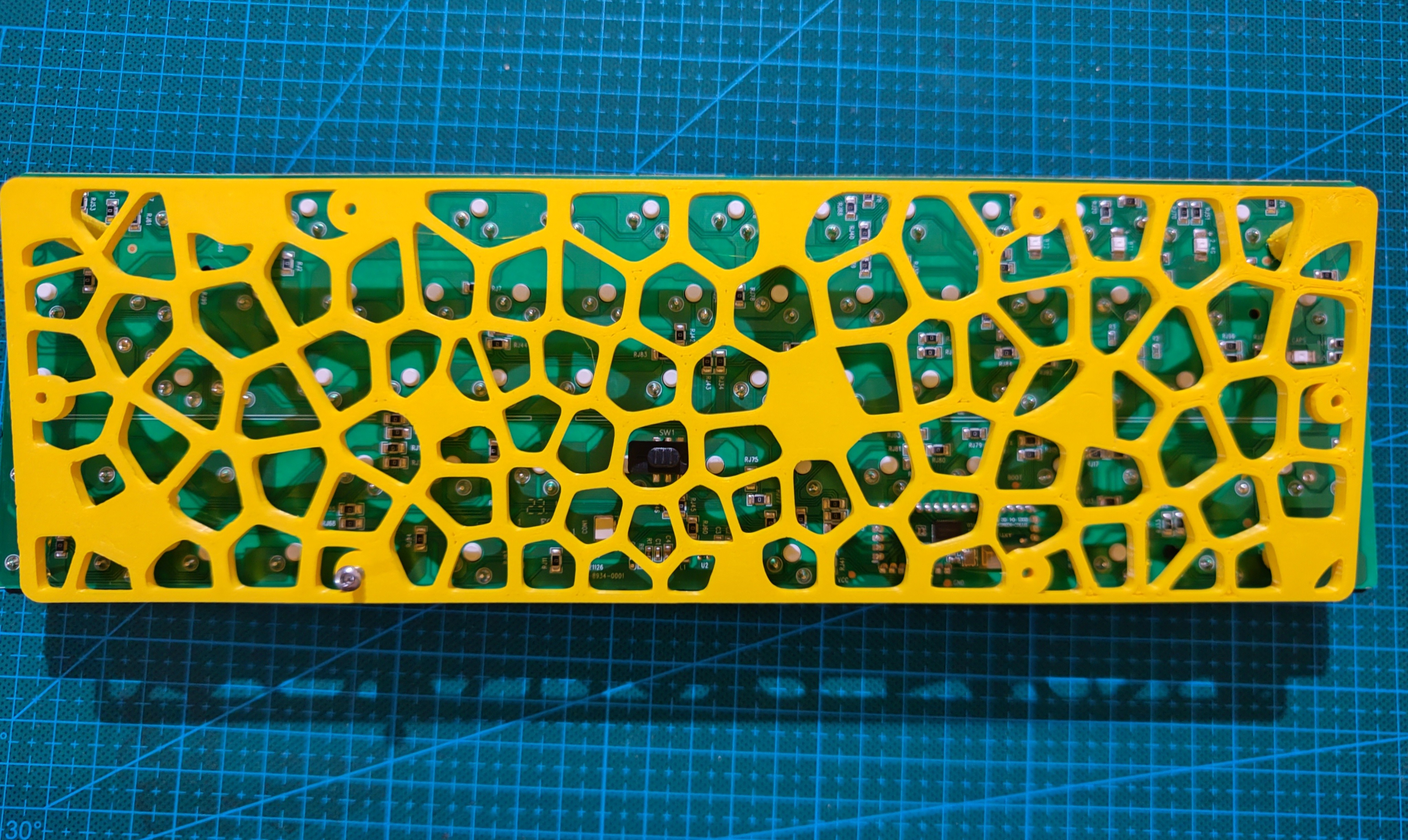
Meanwhile, I wondered every now and then how I'm gonna fit the shell in my 3d printer. First of all, I need to be able to open the case, so no whole body prints or glueing. Before I showed this image, which has the keyboard support posts.
![]()
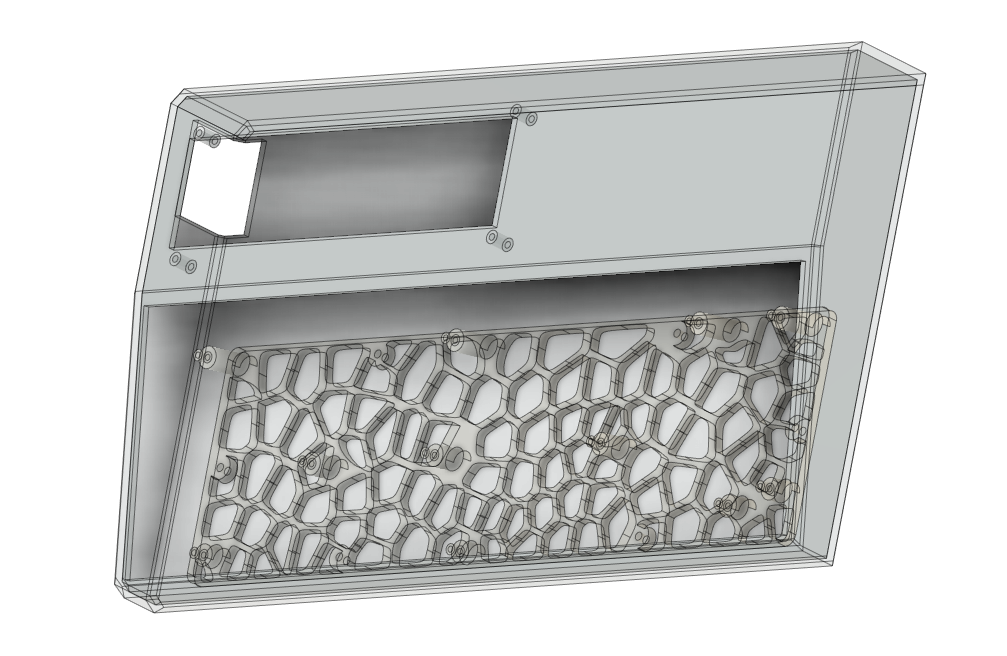
Since I'm planning to print the body on its side, these posts would be a huge pain to support. So, yesterday I got to cut them from the main shell and add them to a plate.
![]()
Notice the voronoi pattern? I have been wanting test it and since this will be hidden anyway, I used it here. Thus, I got to print the support plate with only 50g of PLA.
![]()
I guess this is officially the first printed part that will be in my cyberdeck. Now to figure out hot to break the shell in two parts for printing.
-
Entry 0x0E - Test printing results
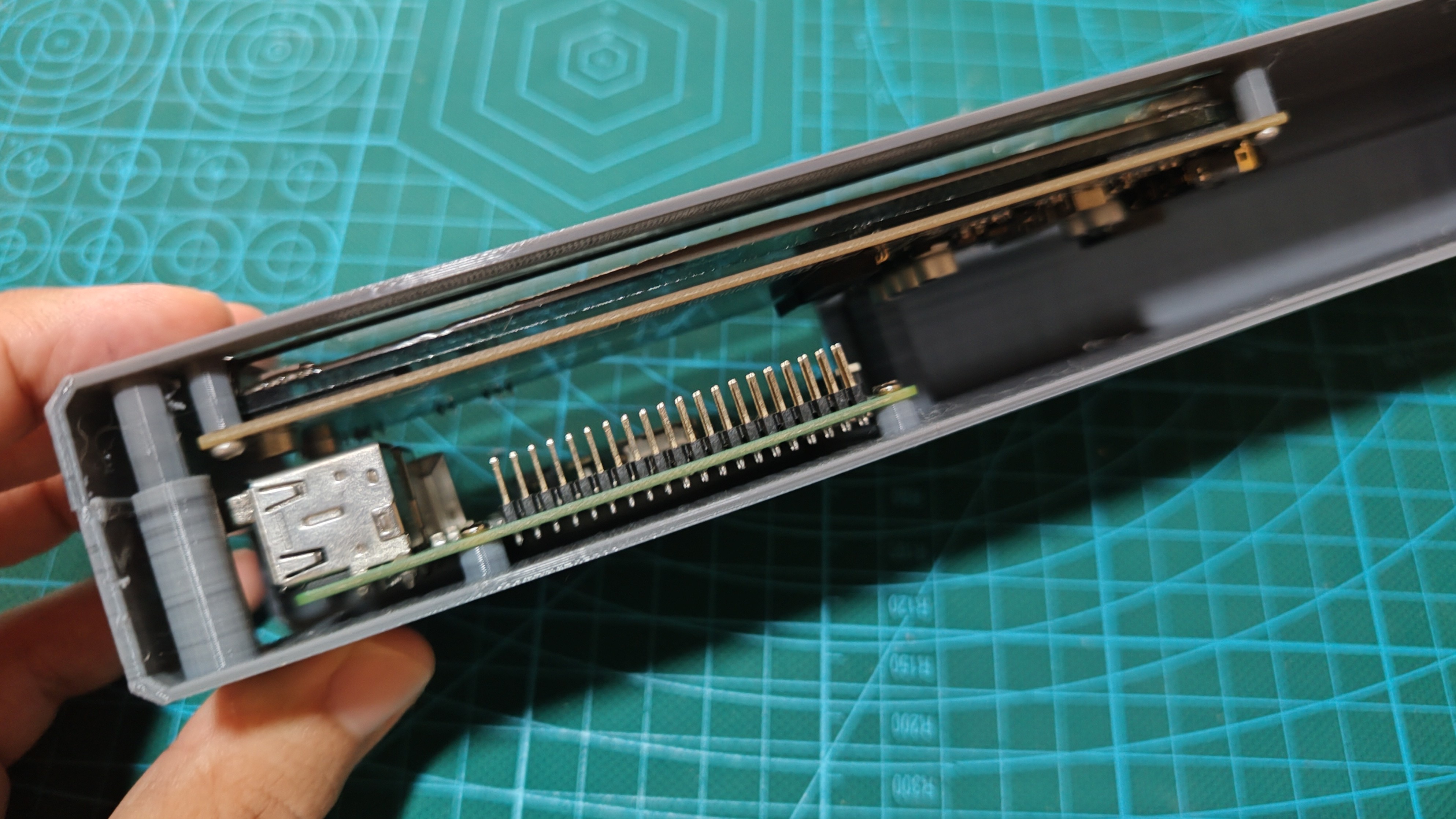
08/06/2023 at 13:34 • 0 commentsYesterday (Saturday), while I was figuring out stuff about SPI drivers in the Linux Kernel, the printer was very busy. I have some low cost material I am using for these tests, which has lower quality but it is ok for testing dimensions.
![]() The hardware seems to be correctly positioned and dimensioned, and that is a relief. This is my second time designing something in 3d, so that is why I'm taking this design-print-test approach.
The hardware seems to be correctly positioned and dimensioned, and that is a relief. This is my second time designing something in 3d, so that is why I'm taking this design-print-test approach.
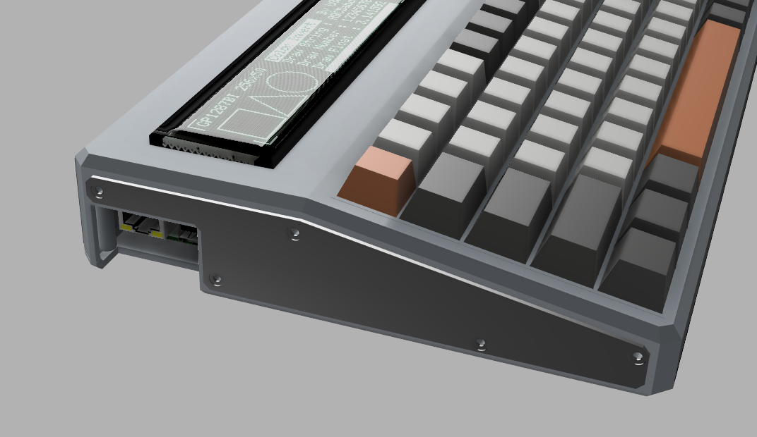
I was a bit worried about the clearance between the raspberry pi and display. I need these in the same side because the empty space on the right of the deck is reserved for a power bank.![]()
I also learned a few things with this print:
- Screw posts need to be wider, but I made them thin without reasoning and one broke easily.
- Also, probably should have had taken the precaution to make infill higher on the posts.
- Hex screws look awesome on the outside, but I've had a harder time to screw them to hold the two pieces together.
- I'm using 2mm for the walls and in this size it becomes a bit wobbly.
SPI Driver update
At this time I have added the commands from the datasheet and started to figure out how to connect to the raspberry pi spi from my driver.
#include <linux/module.h>
#include <linux/init.h>
#include <linux/spi/spi.h>

#define GP1294AI_CMD_RESET 0xAA
#define GP1294AI_CMD_FRAME_SYNC 0x08
#define GP1294AI_CMD_BRIGHTNESS 0xA0
#define GP1294AI_CMD_DISPLAY_MODE 0x80
#define GP1294AI_CMD_WRITE_GRAM 0xF0
#define GP1294AI_CMD_DISPLAY_OFFSET 0xC0
#define GP1294AI_CMD_VFD_MODE 0xCC
#define GP1294AI_CMD_OSC_SETTING 0x78
#define GP1294AI_CMD_EXIT_STANDBY 0x6D
#define GP1294AI_CMD_ENTER_STANDBY 0x61

#define GP1294AI_MAX_FREQ 4167000u
#define GP1294AI_DEFAULT_BRIGHTNESS 0x0028u
I sent a few full pointers to the kernel but now it seems to be loading correctly. Hope to figure out how to send dat to the spi yet today(Sunday), so I'm hooking up a logic analiser board to the spi.
-
Entry 0x0D - More printing tests / Display Driver
08/05/2023 at 14:25 • 0 commentsTesting setup
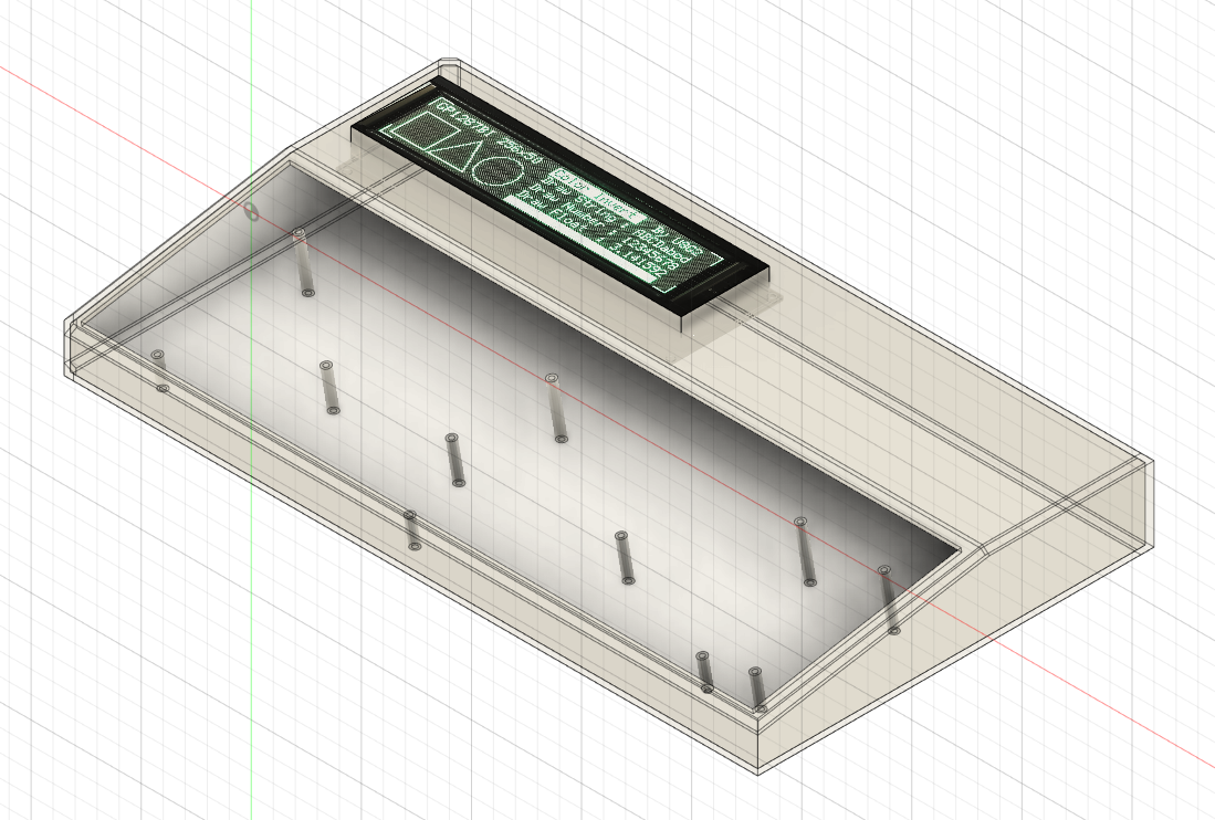
It's Saturday morning and I finally have more time to spend on this. Yesterday I got to cut and tweak a few parts of the basic design that I'm printing right now, so that the printer is budy while I study driver development.
![]()
I just cut the upper front and back of the case, where both the raspberry pi and display will be mounted. Added a inner lip and screw posts to hold the two parts together. My goal with this is simply to test if the display and raspberry pi are correctly positioned, but I will use this as my setup for testing the display and raspberry pi communication while developing the driver (if successful dimensioned).
Driver development
Yesterday I was studying driver development and it seems that Linux the kernel changes fast and some resources I was reading before are obsolete. Only now I got to really sit down to code, but I did not want to code on the raspberry pi via SSH, so I created a samba share that I access on my desktop and then I program using Visual Studio Code, which I'm already more comfortable with.
#include <linux/module.h>
#include <linux/init.h>
#include <linux/spi/spi.h>

static int __init gp1294ai_init(void) {
    pr_info("Initializing gp1294ai display!\n");
    return 0;
}

static void __exit gp1294ai_exit(void) {
    pr_info("Unloading gp1294ai driver\n");
}

module_init(gp1294ai_init);
module_exit(gp1294ai_exit);

MODULE_LICENSE("GPL");
MODULE_AUTHOR("Robson Couto");
MODULE_DESCRIPTION("Linux driver for the GP1294AI VFD");
For the time of this log I only have a skeleton module, but I hope to have most functionality from the datasheet in the driver as functions while I go about figuring out how to use SPI from inside the driver.
KOAT0 Portable Terminal
A cyberdeck with a fluorescent display for max cyberpunk looks

 I've watched some videos on detailing, although not about cyberdecks, but still really useful tips for making props and models look hi-tech.
 I also took the opportunity to touch up the ethernet and USB ports cutout from the raspberry pi on the side of the deck and I'm so proud of that :)
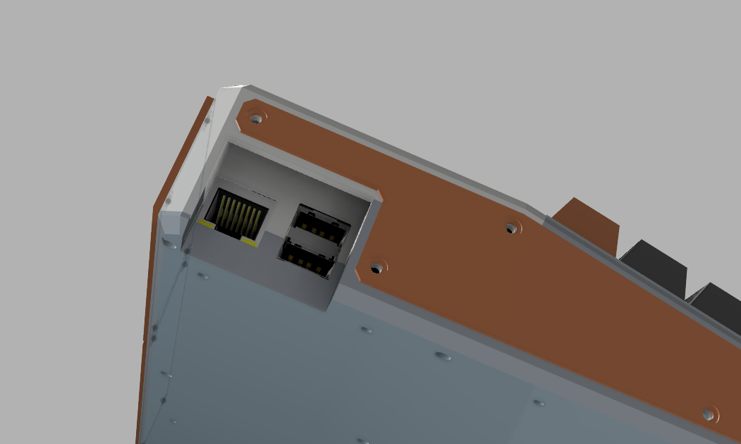
 The hardware seems to be correctly positioned and dimensioned, and that is a relief. This is my second time designing something in 3d, so that is why I'm taking this design-print-test approach.