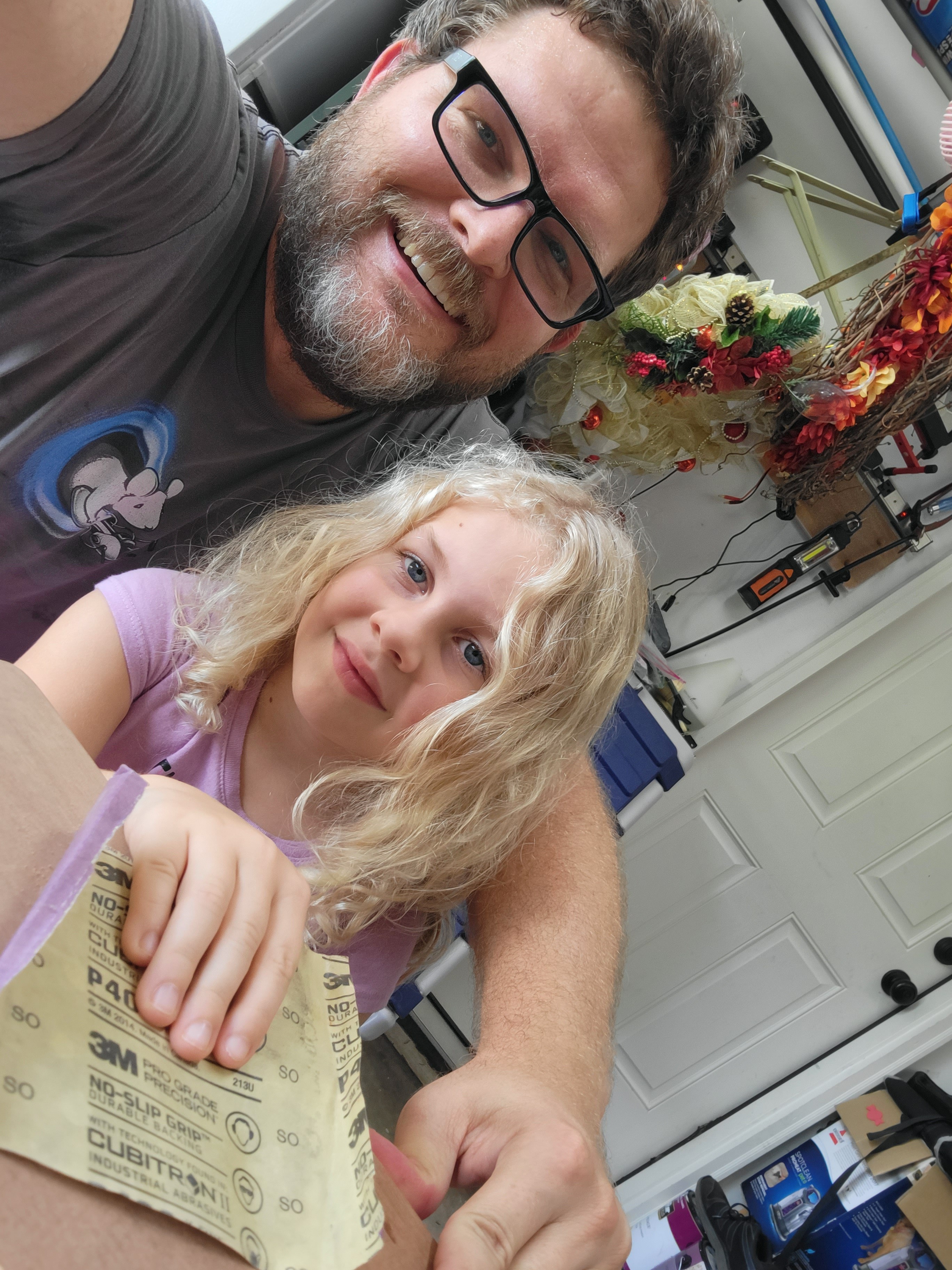
Over the weekend, my daughters helped me sand the board that the switches will be installed in, paint it, and install the switches. Here's some pictures of the progress.
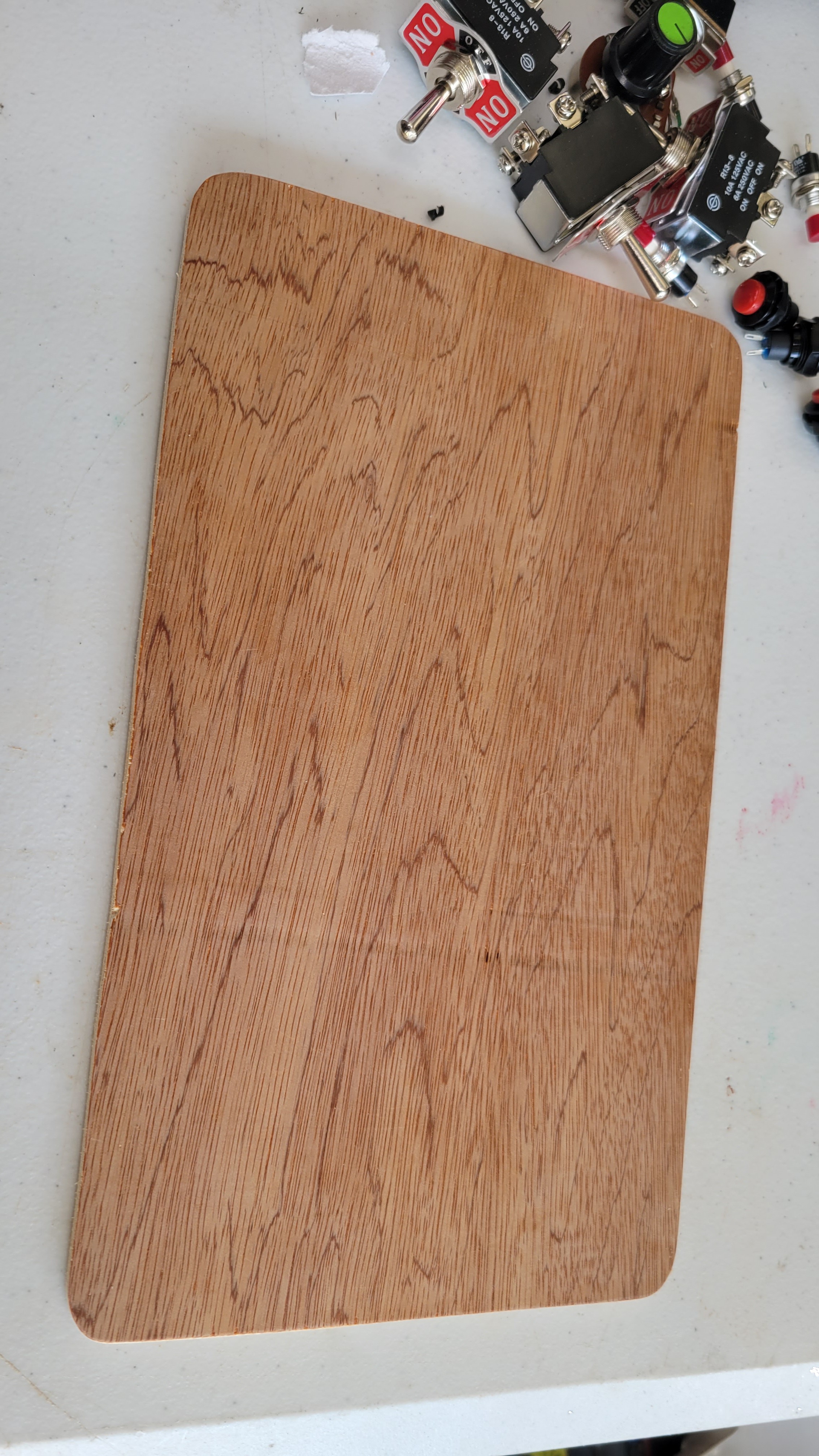
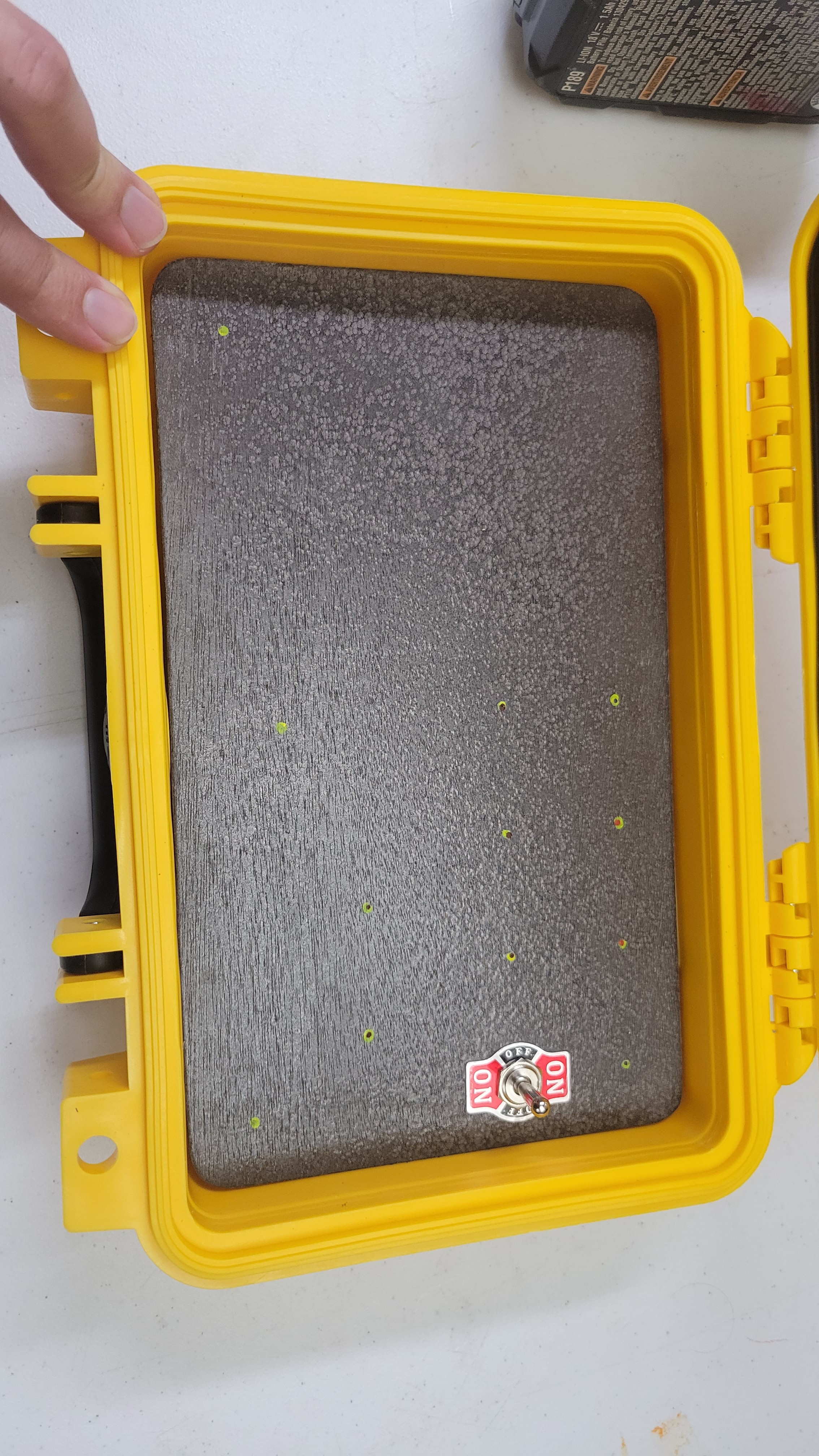
Here's the board fit into the box for the switches.
It's pretty smooth, but we still should sand the edges (with Daughter 3):
Time to pick the paint (with Daughter 2)! She chose the hammer tone paint:
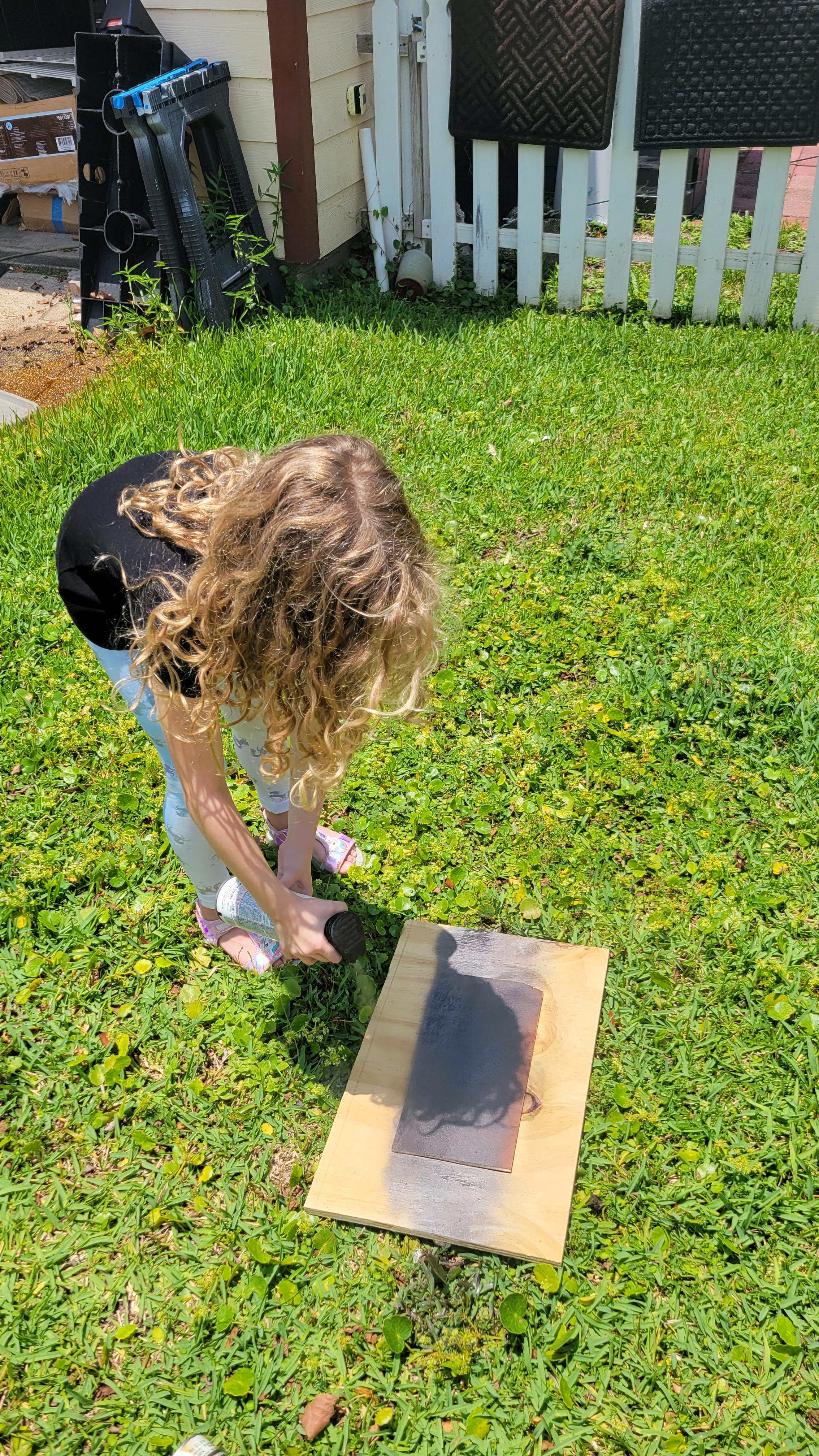
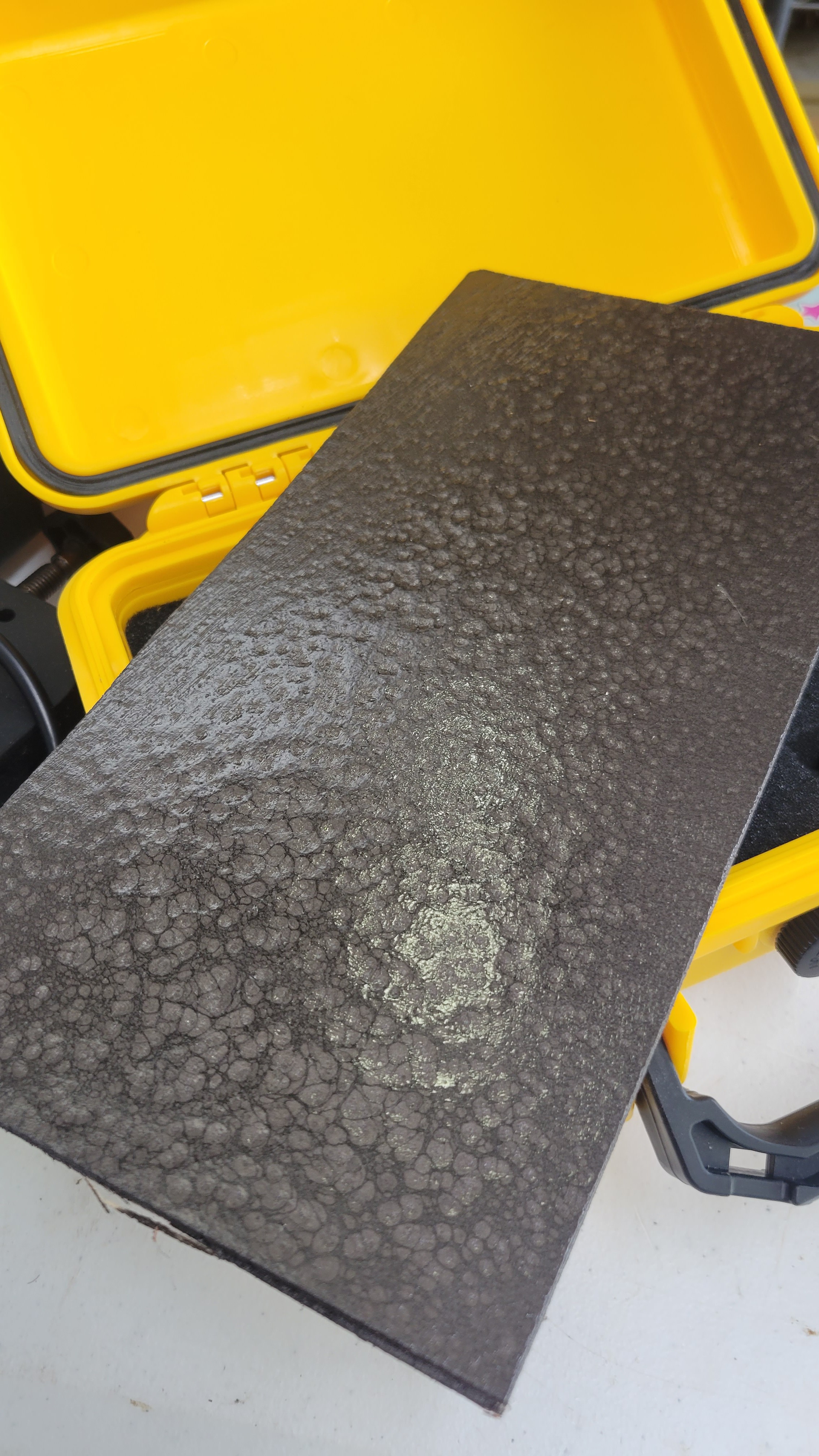
Learning to spray paint! (this is a test piece)
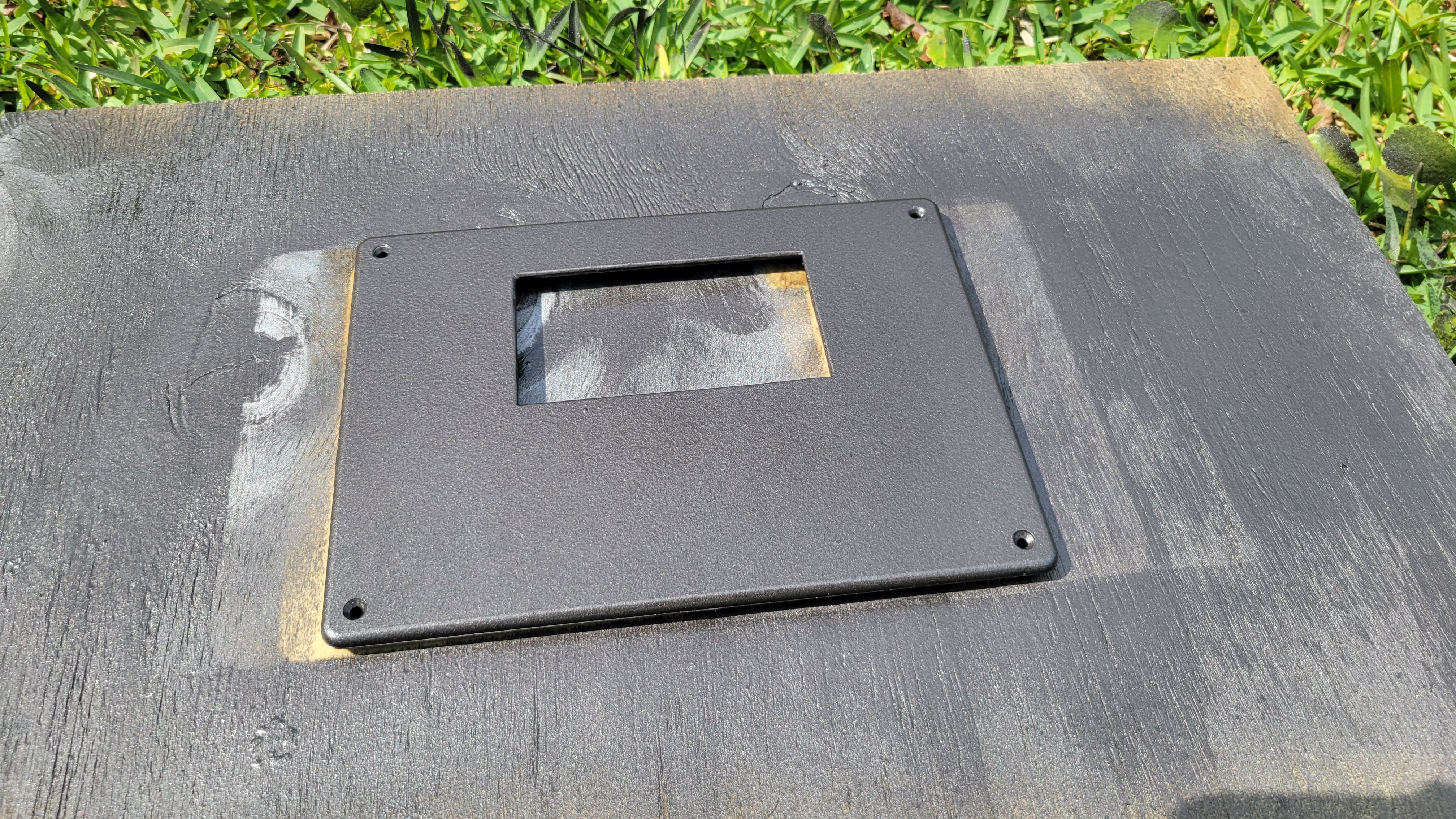
Spraying the display bezel:
Test piece turned out great. Then it poured rain and I didn't get pictures of spraying the fit piece.
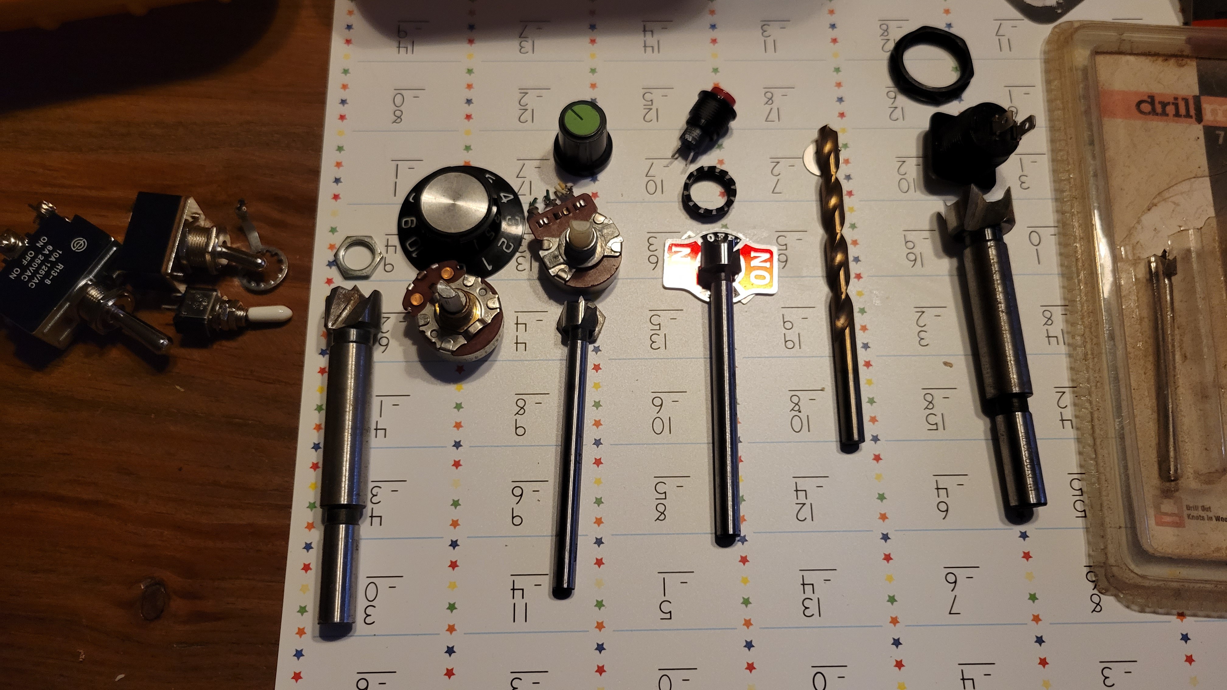
Selecting drill bits for each switch and pot:Board is marked out and one hole drilled for test fit.
Test fit looks good! Drilling holes with Daughter 1!
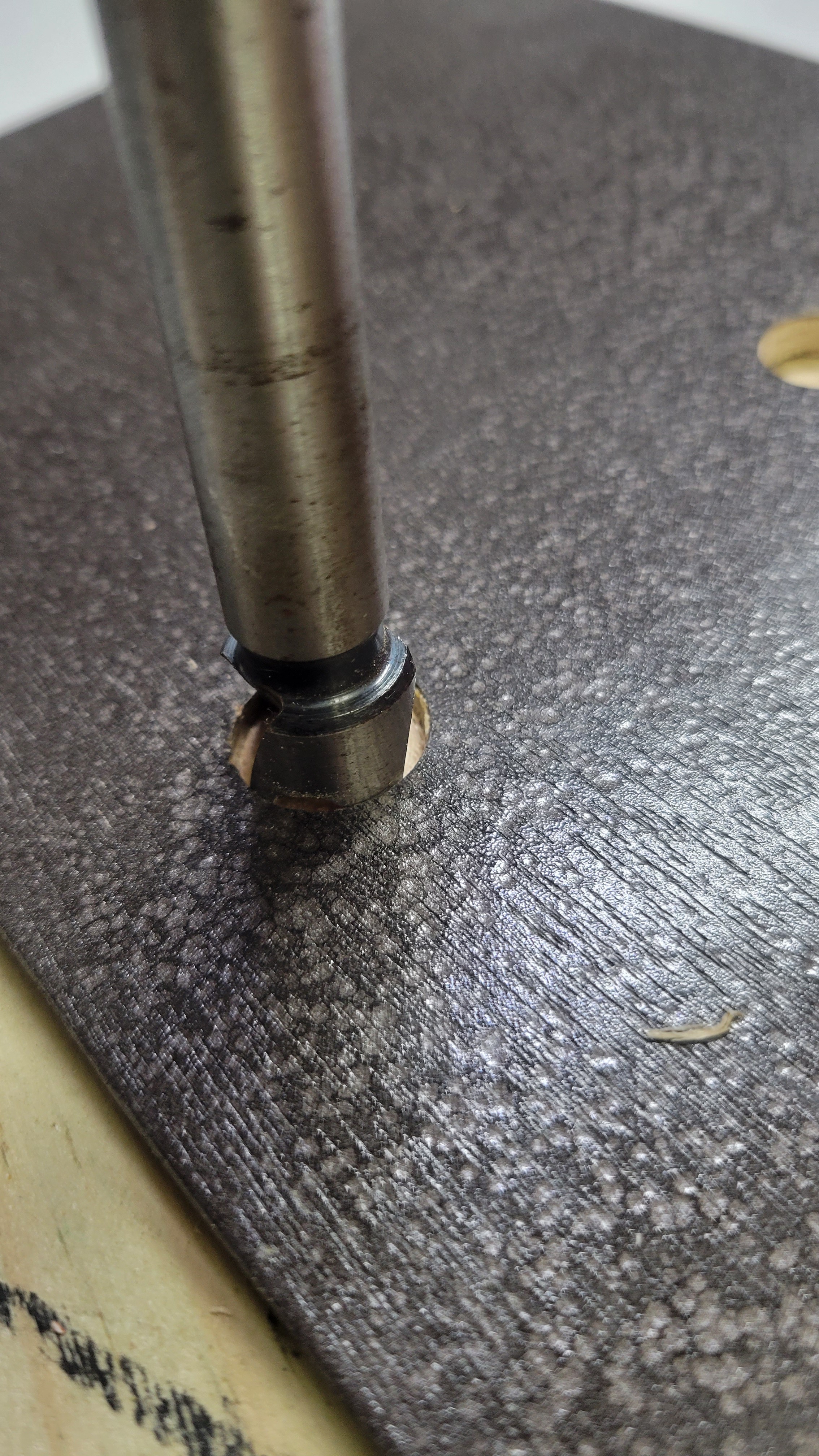
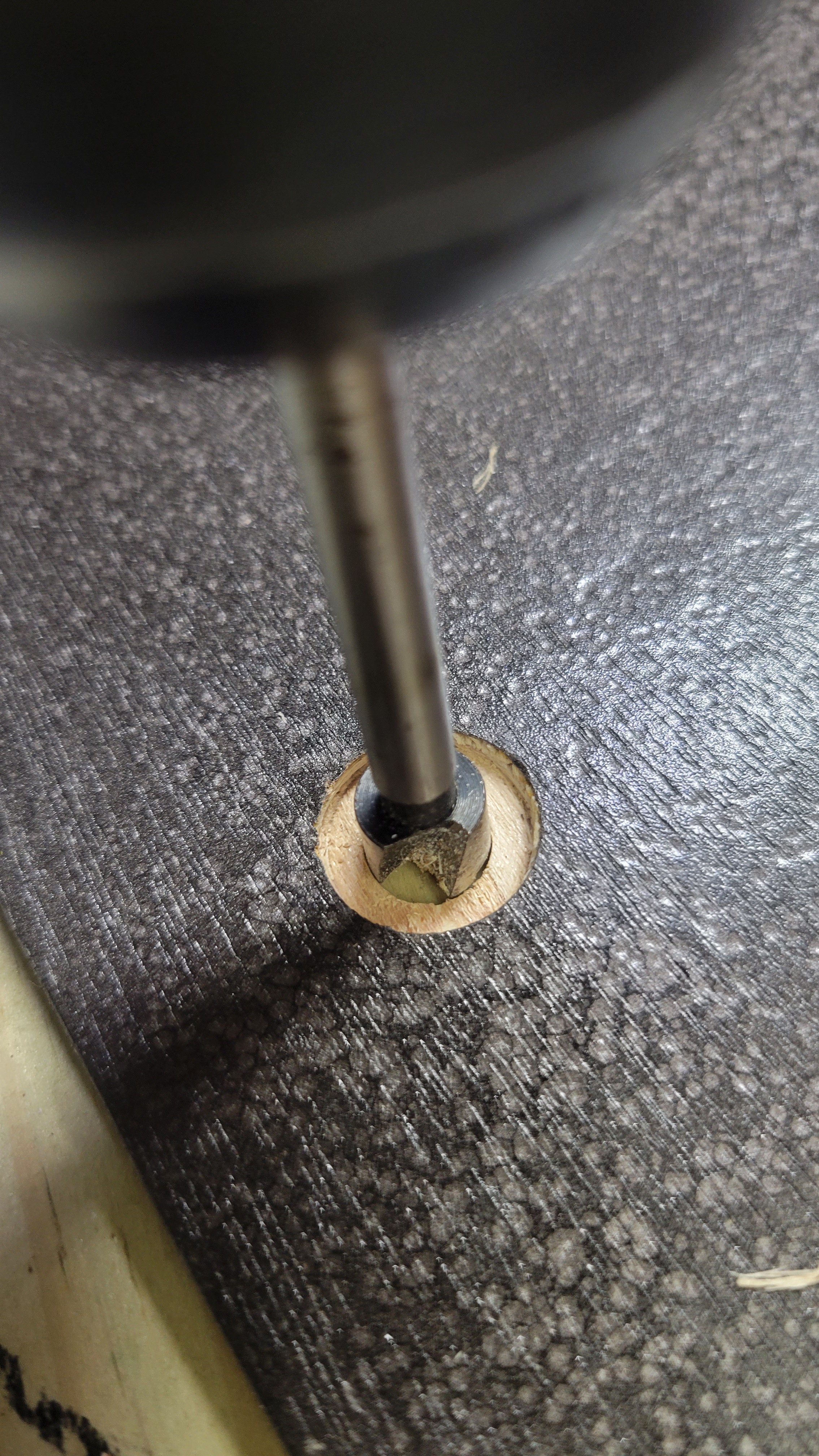
The pots don't have enough thread for the board thickness, so we have to drill half way through big enough for the nut (but smaller than the dial):
Then drill the rest of the way for the threads:
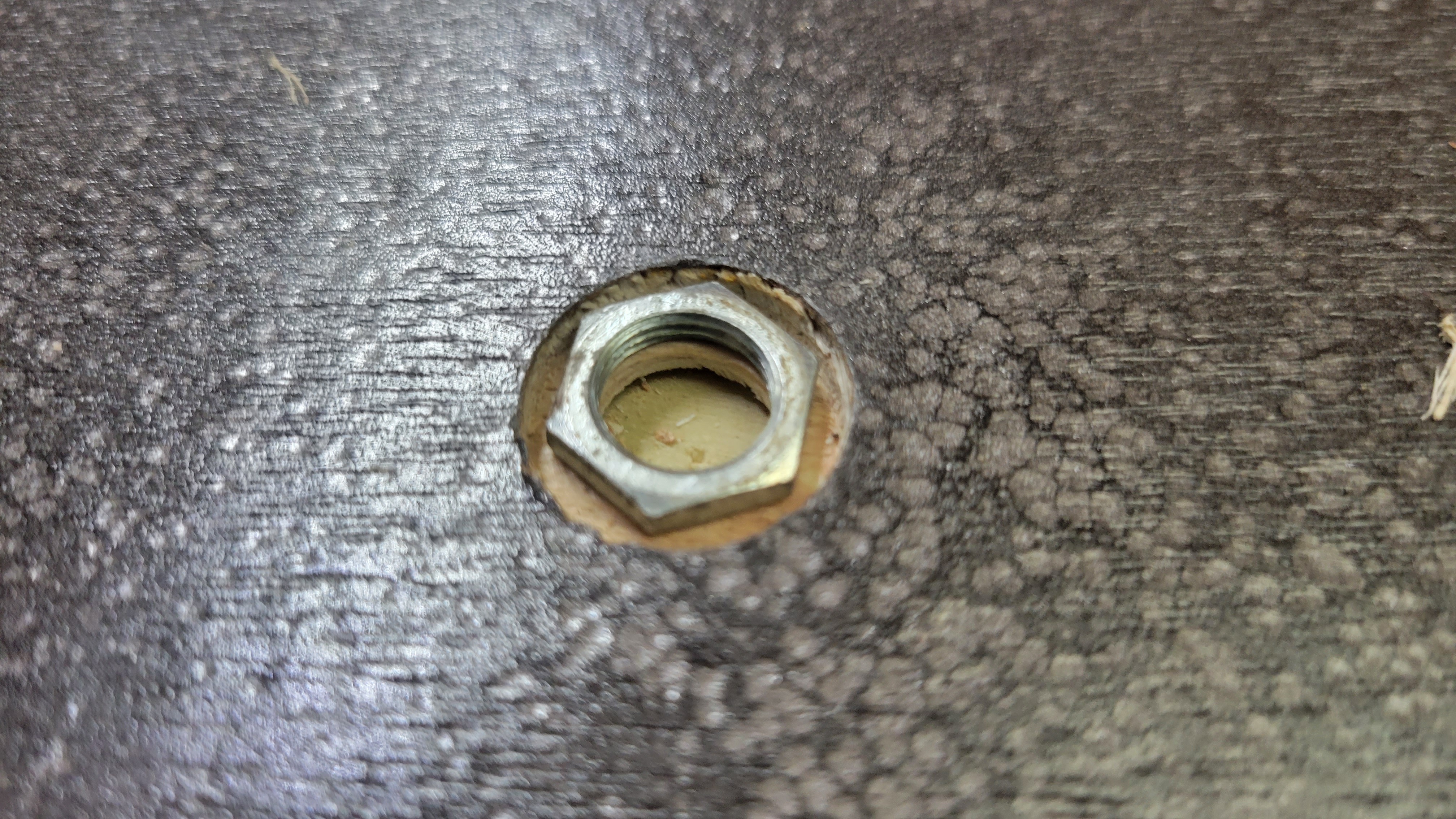
The nut sits flush with the top now.
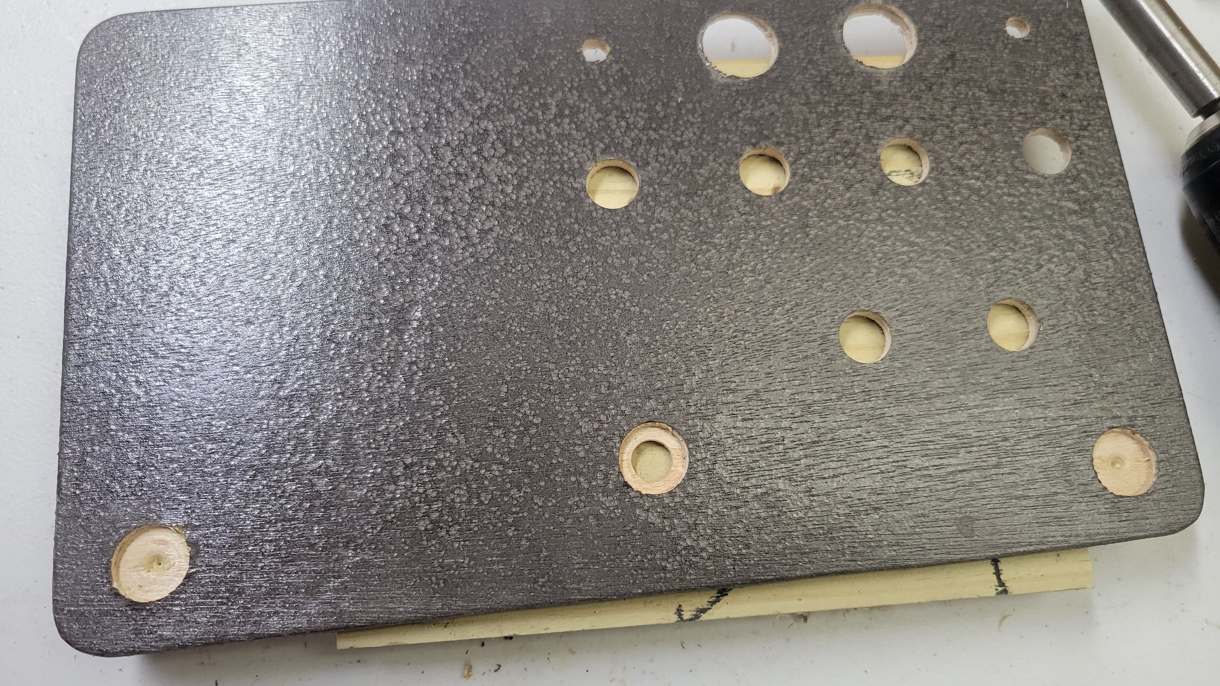
Almost finished drilling... just have to finish the corner pots and "Simon Says" buttons.
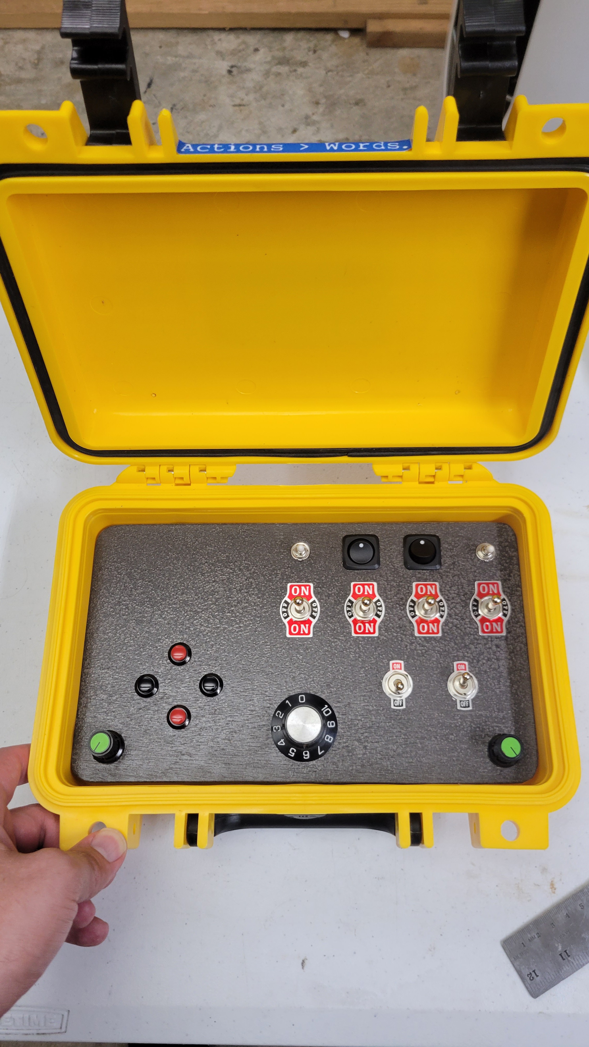
It got late and I didn't take pictures of the assembly process, but here is the finished interactive board. It's not mounted yet, just sitting in there.
I just realized I forgot to buy LED holders... I may try to simply drill a hole slightly smaller than the LEDs and use a press-fit and glue first though. I also have the dilemma of having to solder a current limit resistor on to 22 different LEDs. I may have to cheat and order pre-wired LEDs for 2 day shipping.
I don't have time to write my own code for this so I employed the help of chat GPT over the past week. I will share my complete conversation in a link when it's finish but I'm not sure anyone would want to read it completely. Here are a few tips for coding with chat GPT:
Chat GPT has a limited token memory, so it's a good idea once your code gets to be a decent length to copy and paste your entire code into the chat window to refresh chat GPT's memory. Once you get code that will likely exceed the token count this won't work and you will have to just paste snippets where you want to ask questions.
Ask ChatGPT less rather than more. Because it's training set is vast it will very likely give you a different method to accomplish what you're looking for. If you're not sure you like the code it gives you simply ask it if there's a different or more efficient way.
If you're not sure how to hook things up, let it help you develop the architecture before you develop the code.
If you know where you have everything plugged in, give it a list of the pin assignments and have it help you choose variable names if you want.
Once you start developing code, use something like wokwi.com or directly run the code on hardware. You're not going to get working code the first time with a moderatly complex project.
When something doesn't work on the simulator, you can simply ask chat GPT why it didn't work and usually based on the previous conversation it can tell you why without having took paste in the code again. However after going back and forth a few times and fixing your code, feel like they want to repaste all of your code again for the smaller projects to refresh the token memory.
Right now I have lights set to light up when nearly every switch position is set, so that my son gets a 1:1 cause/effect.
I'm still fighting with ChatGPT about how to make the Simon says buttons work...
You can check out the current state of the code by going here:
Here's the ChatGPT conversation. It stops as of yesterday, July 16, which hasn't solved the buttons yet, but you can get a good sense of how I'm using it to code.
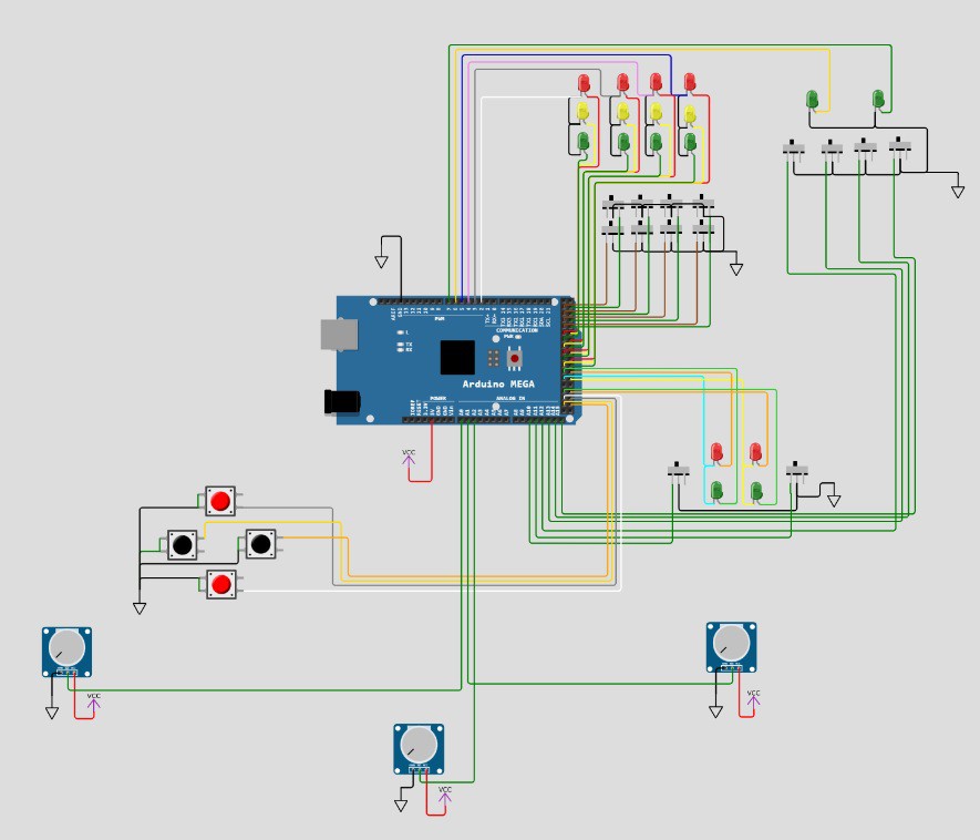
I have decided on a general layout for the components in the case as follows:
At the top right you can see 2 green LEDs and 4 switches. The center two switches will function as "soft" power switches to activate two main sections of the board. The switches on the left and right can then activate subsections of the board as well, or just do something with the two LEDs up top. Both LEDs are on their own PWM channel. (Obviously they can be programmed to do anything... but this is the start.)
In the top center section you can see 8 switches and 12 LEDs. This is actually representing 4 on-off-on switches, with an LED at each position next to each switch. This section allows some puzzles to be created to match the switch position, for example. (Wokwi did not have a SP3T switch so i'm simulating it with two switches and don't have time to figure out how to do it another way)
I have wired the 12 LEDs so that each triplet of LEDs associated with a switch has it's own PWM channel, as notionally I would only have one of the three LEDs on at a time and it gives more control of dimming with the hardware PWM. The PWM pin will drive the common anode connections and enable me to dim each set of 3 while turning the individual LEDs on using the Digital pins on the Cathode set to LOW. (...and I just noticed that I have all 12 of those LEDs backwards in the schematic, so on/off and PWM is reversed as pictured)
In the center below that are two SPST switches, along with a LED for each position. Again each switch pair is driven by PWM and a digital output for on/off.
The pots are a little different story. They are obviously hooked to the analog inputs, but the one in the middle is actually a 10-turn, whereas the outside ones are just standard 270ish degree turn. My plan with these is to initially control some dimming of the LEDs. Later on I want to add 2 .98" OLED displays and use the pots for game inputs.
The buttons... These are also intended to be used later for game input. I don't have LEDs for them, but I may add some. I do have several outputs left and it would make for an easy simon-says type game.... I think I'll add that next....
Since I don't have time to retroactively log what I've done, here's where I'm at.
I currently have a rugged waterproof case, a promotional video brochure that has been disassembled, and Arduino mega, and a bunch of switches, LEDs, and components, along with a couple different potentiometers, some mini OLED displays, and a plethora of other things that I probably shouldn't try to include.
I have cut a piece of thin veneer plywood to fit the bottom of the case. I plan to Mount all of the switches to this.
Goal:
My goal is to place a decent number of switches on the board, along with enough LEDs to depict each switch position. I'm laying them out so that I can create a puzzle at a later date that requires switches to be turned on in a sequence and the LEDs to visually guide that sequence.
I'm leaving room for the OLED displays but will likely not have time to incorporate them right now.
The promo video card will be completely separate for the moment, and will activate using the hardware that came with it, including the magnet to turn it on when the case is opened. I will replace the three buttons with my own buttons that will be a little more rugged.
Challenge:
The main challenge I see now is power. I think I can design it to run AAAs but it would be nice if I could incorporate a set of 18650s and a charge circuit. The other challenge is determining how to mount the Arduino and all of the wiring to handle the rugged environment of a 2-year-old!
 Josh
Josh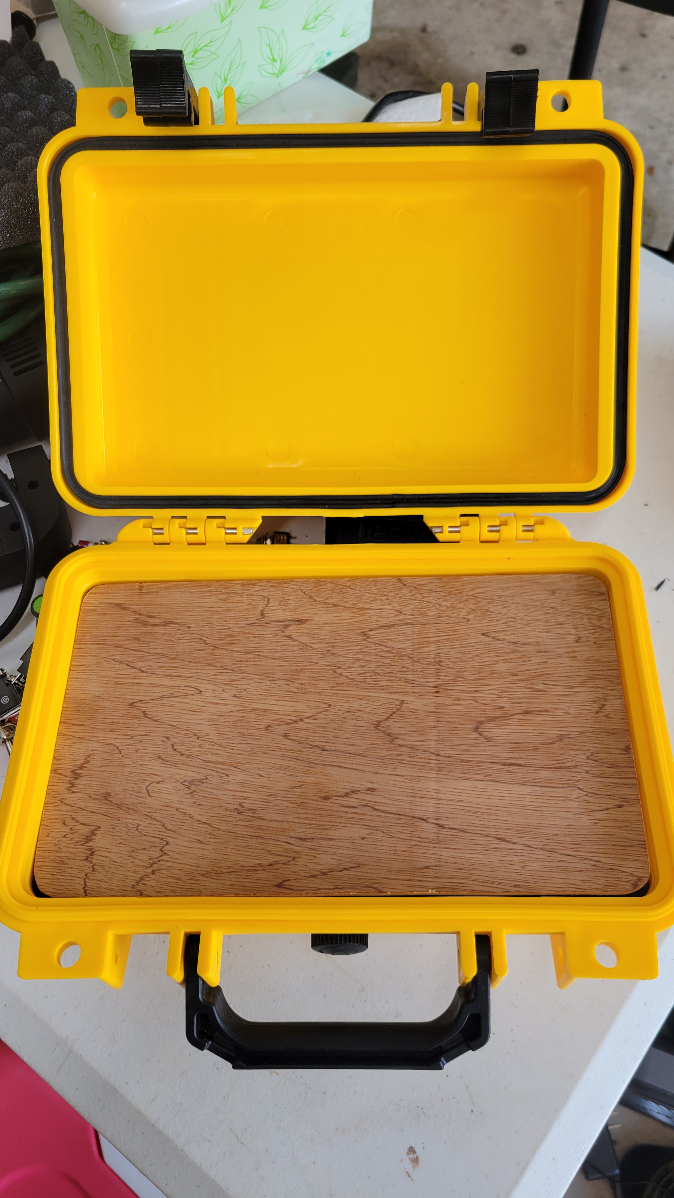
 Time to pick the paint (with Daughter 2)! She chose the hammer tone paint:
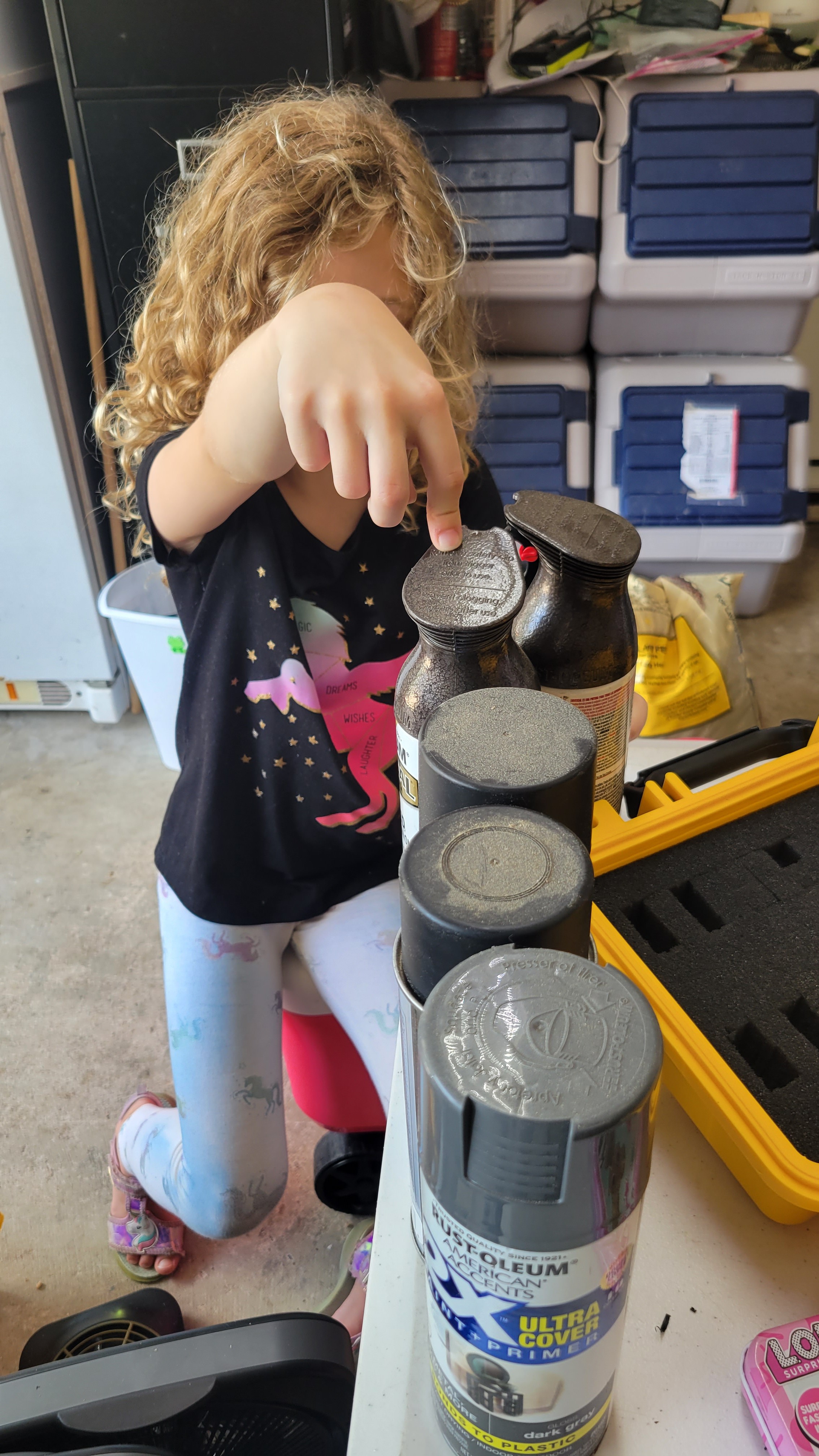
 Spraying the display bezel:
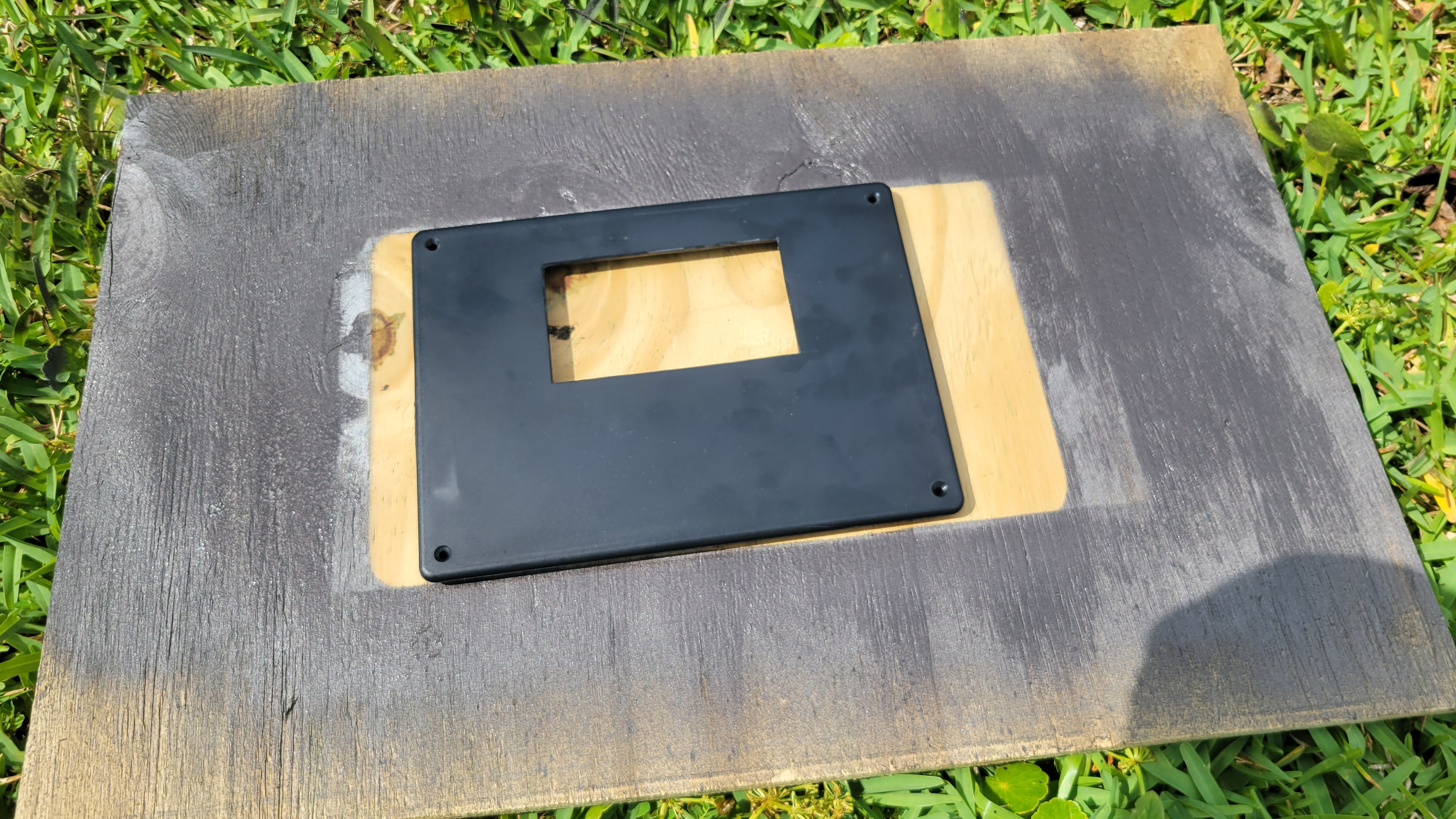
 Board is marked out and one hole drilled for test fit.
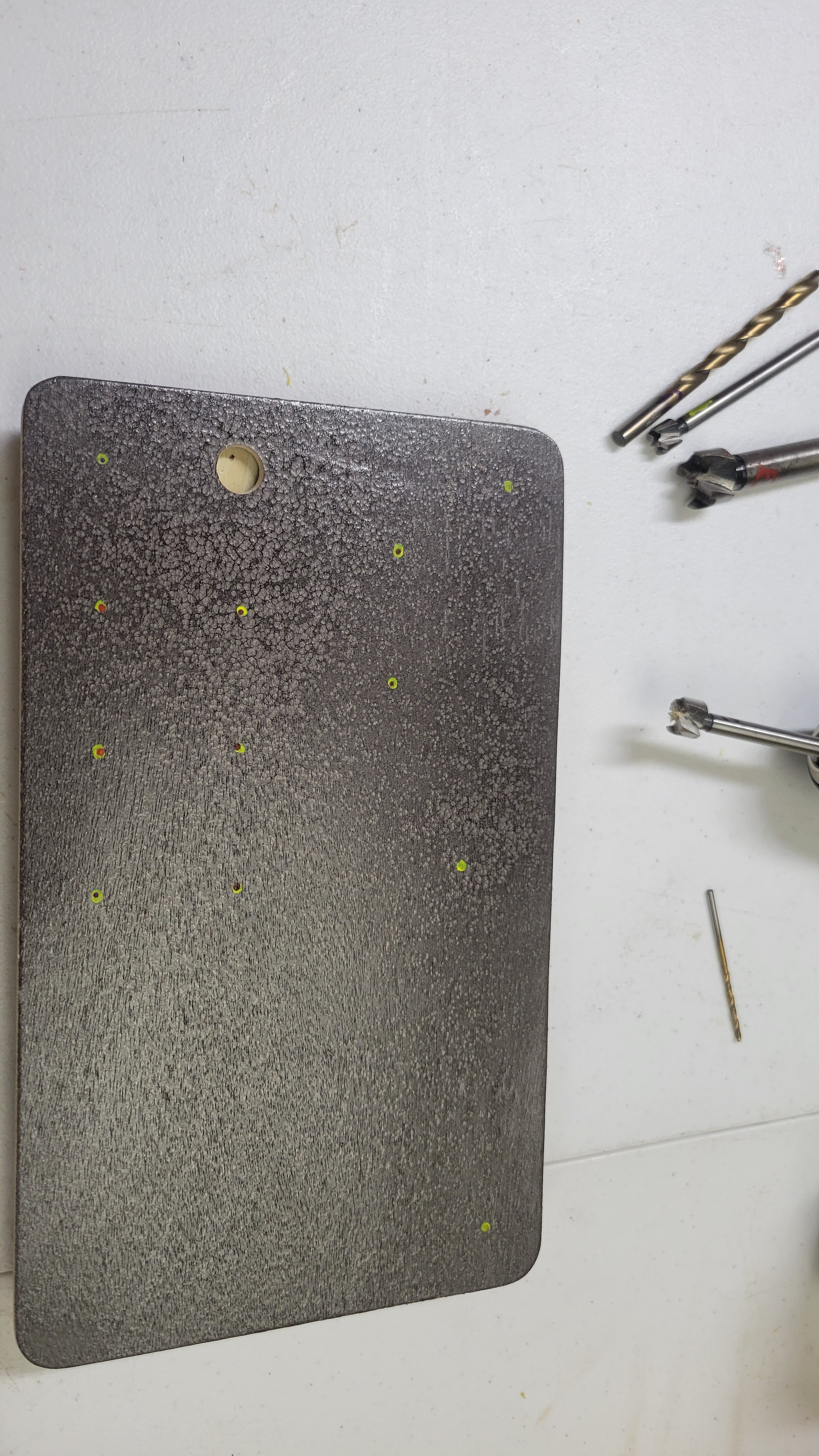
 Drilling holes with Daughter 1!
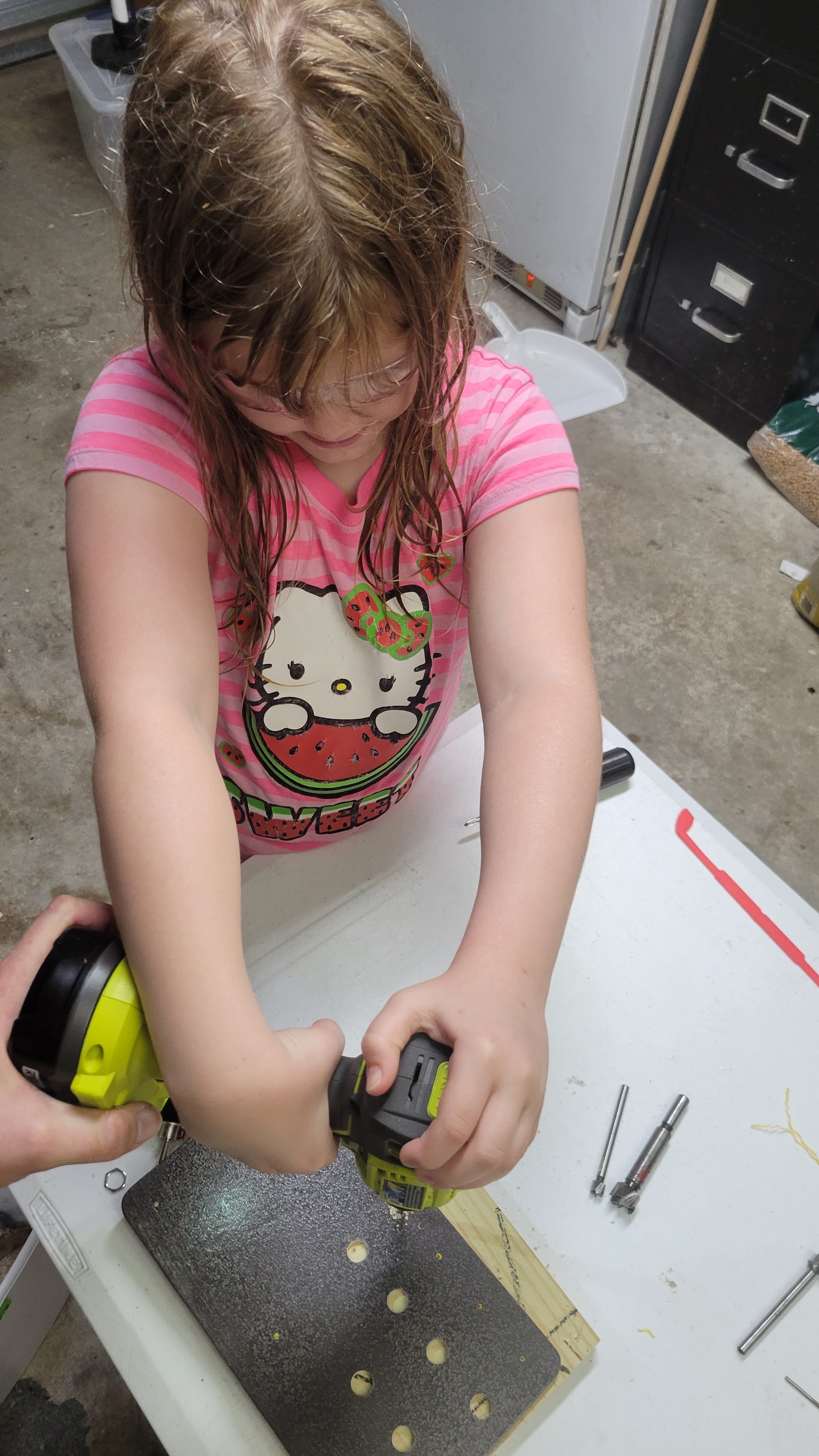
 Almost finished drilling... just have to finish the corner pots and "Simon Says" buttons.