This is not a complete instruction and should be used more as info to inspire your own build. Ill try to document and show how I did stuff, but before and during the build I expect you to re-measure and adopt. You will probably not be able to use these instructions without modification and some of your own engineering. I will not promise that this instructions will work out of the box, instead Ill promise the opposite, this will probably not work without changes/adaptations so be prepared for that. :)
I manage to get a wheel-base,break and handle from another wagon (a dumpster find, I found a bad throwaway bike wagon, a North 13.5 Roadster ) and I had wheels (2x20", 1x16" from another wagon) that fit. The width to the build in my info will be based on the wheelbase I used e.g. 615mm and needs to be adopted if you try this with other parts.
Most part I found a my local hardware store, many of the small special screws and stuff could be bought per item or per weight so I almost never had to buy a box of things.
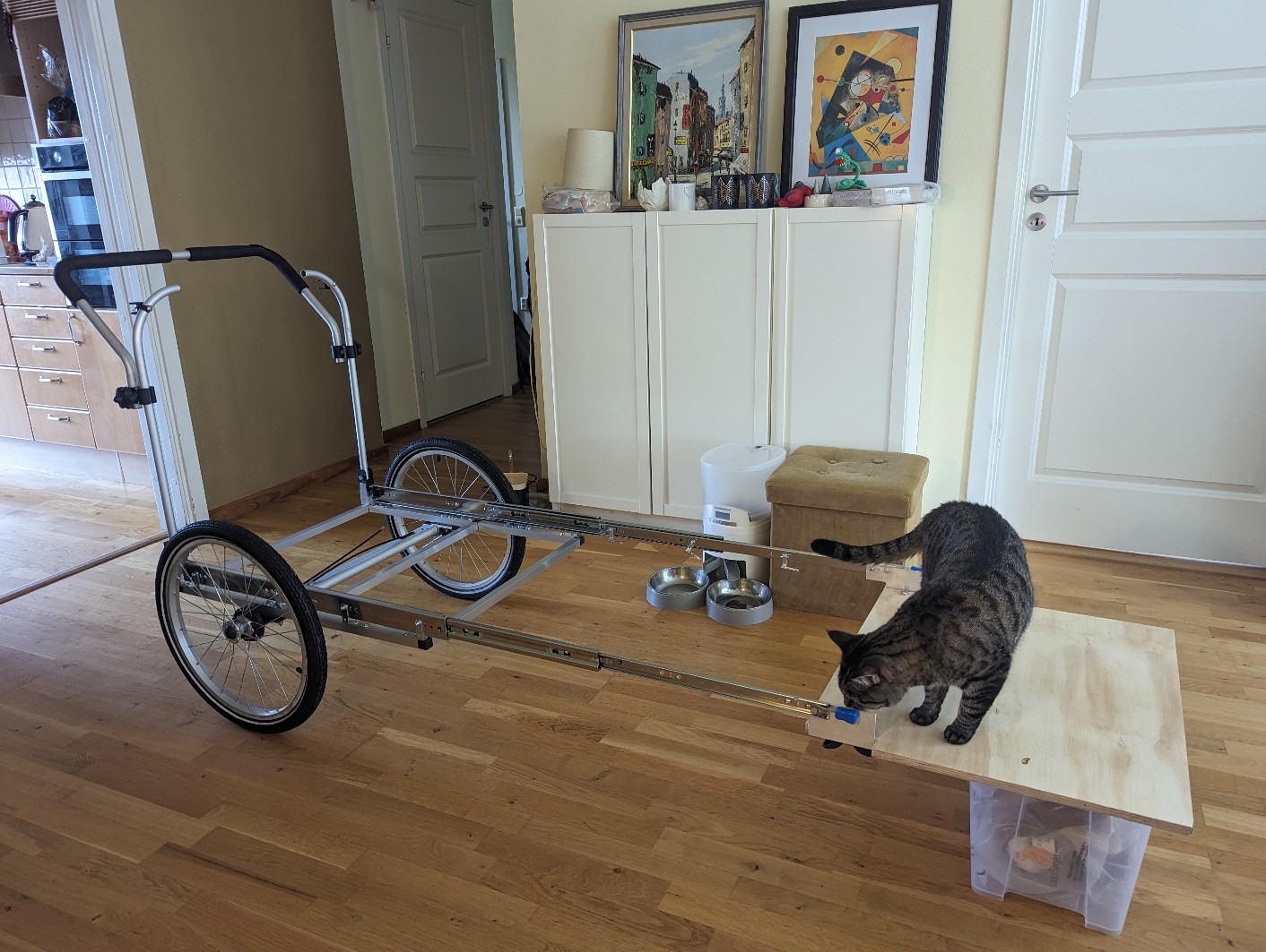
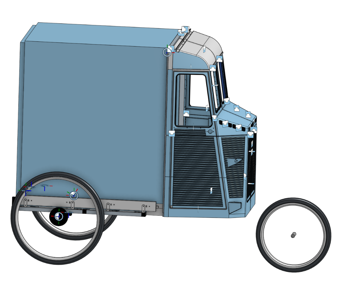
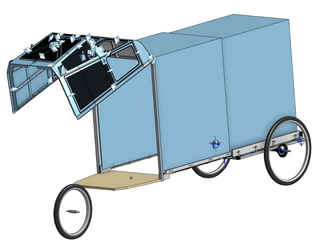
Inital idea for Camperwagon 3.0 is to create a construction with big drawer-sliders on top of the wheelbase that will make it longer when it's time to sleep. The front will open up to access the inside, and if I manage to make an opening on the side that would make it a bit more cozy and is considered as an extra bonus. The main idea with the build it to create a skeleton on top of this and add plasic sheets and make it rain proof. For the look I try to mimic the form of an old Citroen HY van. The design rules with this build is to be more pritty then practic/lightweight but not to bad. The wagon also need to be folded into smaller part for transportaion in car or train without to much work. Sounds easy :)
During the work I started to play a bit with 3D printer, and printed a few angles with the help of my son. The design freedom of this was so great that I got a 3d Printer during the build and have reconsidered "skeleton on top of this and add plasic sheets and make it rain proof" and will probably just 3D print most of the outside. This leavs me with a lot of nice addons but will also require a lot of more desing time. As of now I have keept the old skeleton build as far as I got it and that will be called CamperWagon 3.0 Whne I later add the 3D Printed verions of the build Ill call it Camperwagon 3.1 I will probably remove Camperwagon 3.0 instruction over time when Camperwagon 3.1 get more ready.
2
Create the base
The aim for this step is to create a frame to add the wheel base, handle and the slider.
To think about in this step:
Slider length (750mm in my case)
Width of wheelbase screws.
Position of wheel and slider fasteners so middle beam and wheelbase screws are not in the way.
Leave room in the back behind the slider to fasten a handle (I used 30mm)
I will have a front area sticking out in front of the slider (yes this complicates things a lot) so I selected shorter frame compared to the slider in the front, so it can be fasten in a good way.
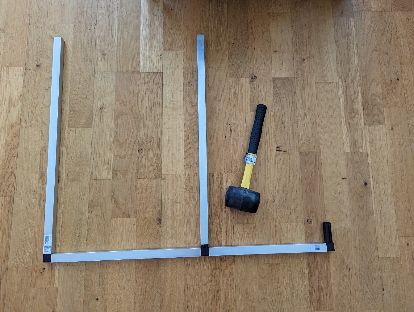
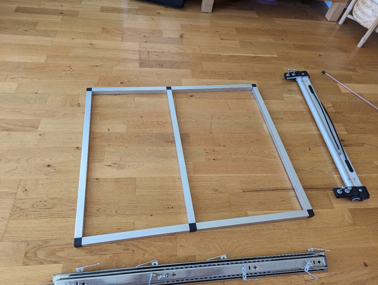
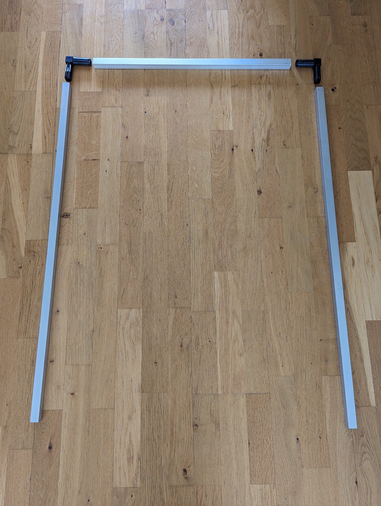
A frame was created using square 20x20 aluminum pipes to fasten the wheel base and sliders on. For the corners I found nice plastic "create a shelf system" corners, The idea here is to make a frame there to keep the wheel base and slider in to proper position. I created it with one middle beam to make it more sturdy, the wheelbase will also work as a middle beam.
As my wheelbase is fasten 595mm apart I select 615mm (595+2x20/2) as a width of the frame so the wheelbase will be fasten in the middle of my 20x20 pipes.
I used the following measurements:
Outer frame size: 725x615mm
Middle beam at 400mm from back
Wheel rotation center 260mm from back
Slider 30mm from back
Main parts used:
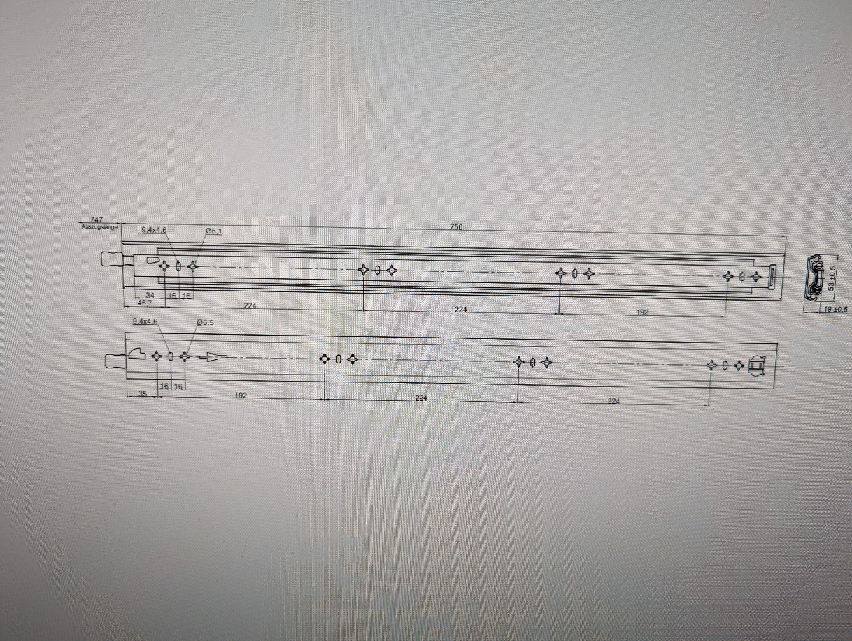
Slider 750 mm with locking
1 pair
For the extendable bed area
Aluminum beam 20x20x1 mm
For frame structure
X-Fastener (X-förbindelse) for Aluminum 20x20x1mm
2 x T-shape 2 x L-Shape 2 x 3way corners
To make the frame shape like a digital 8, The 3way corners was used in the back to create something that I could fasten the handle on, depending on your handle solution this could be replace with L shaped.
Used to hold "bed" when extended inside the bed area. This is used to fasten the 10x10x1mm on each slider.
Aluminum L-beam 10x10x1mm
2x725mm
Used to hold "bed" when extended inside the bed area.
Wheelbase for 2kids bike wagon
1
This will determine the width of the build
Handle with fasteners from (same) 2 kids bike wagon
I got the pipes holding it to the original frame and the folding endcaps to the same handle.
Aluminum beam 25x25x1 mm
150mm
Just used to fasten the handle pipe folding endcaps to 3way X-Fastener (X-förbindelse).
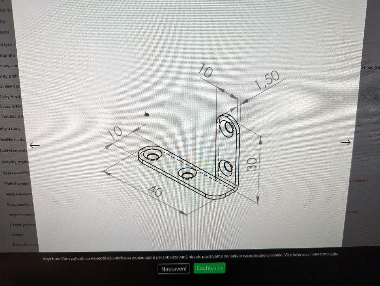
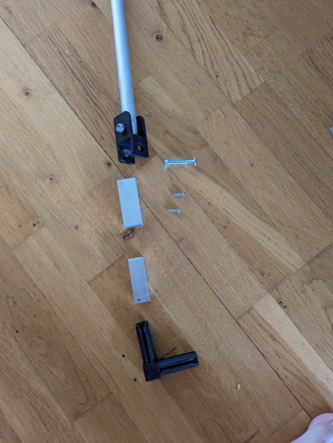
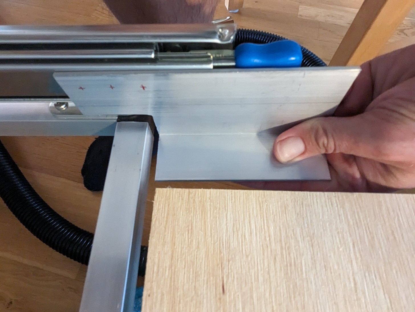
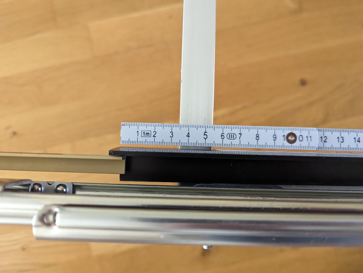
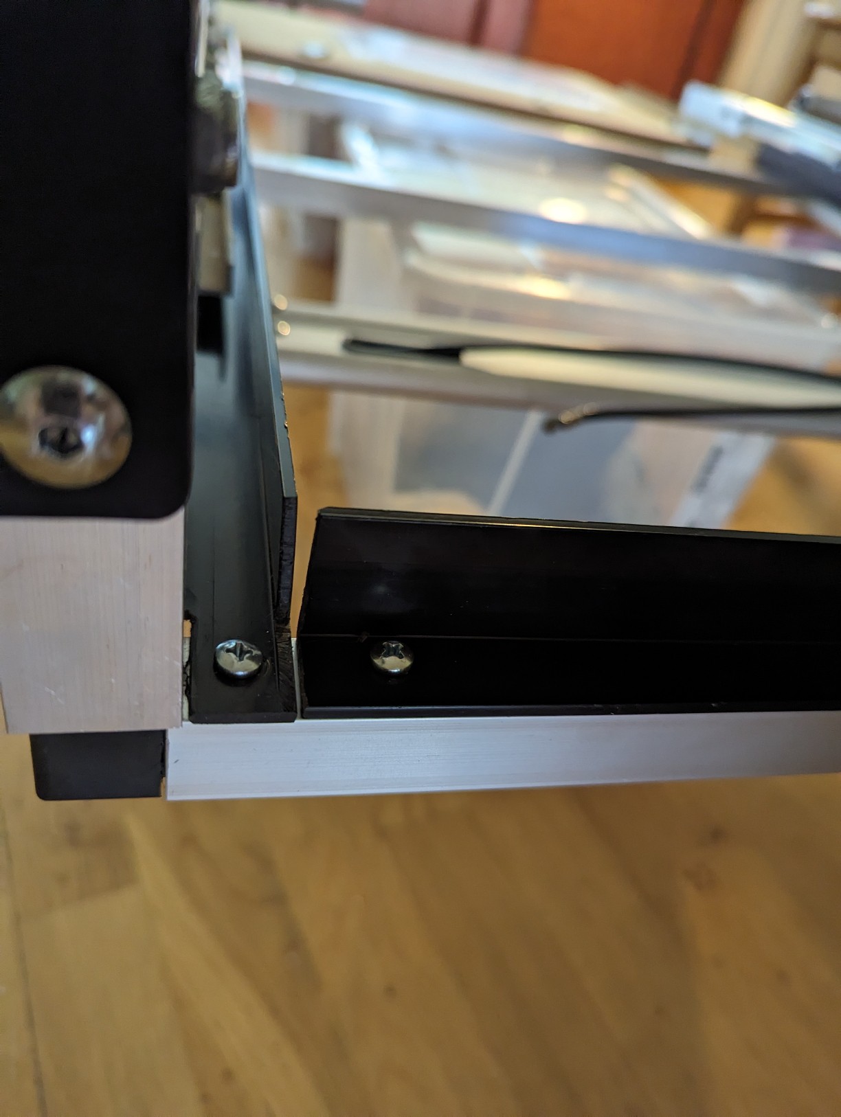
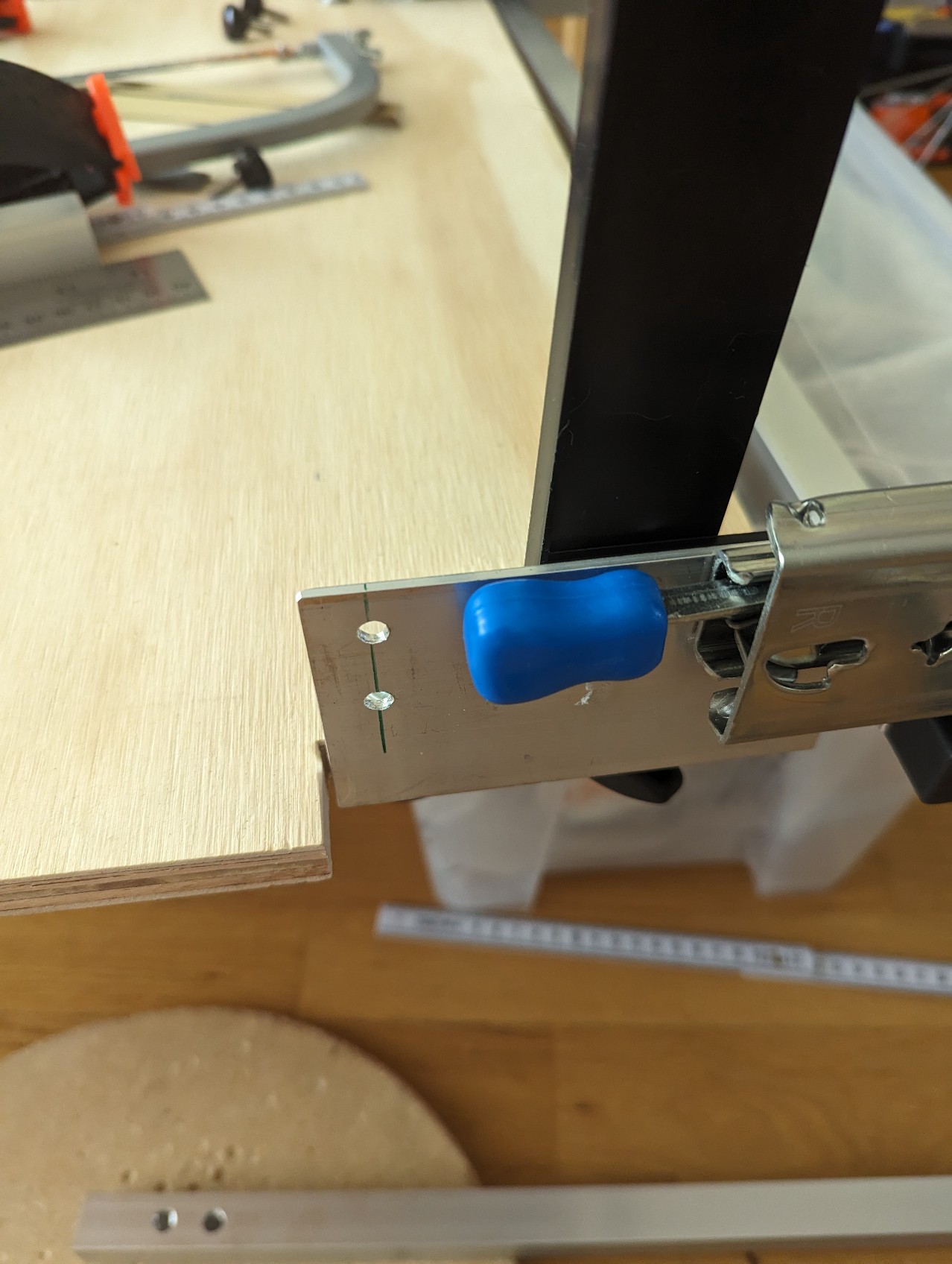
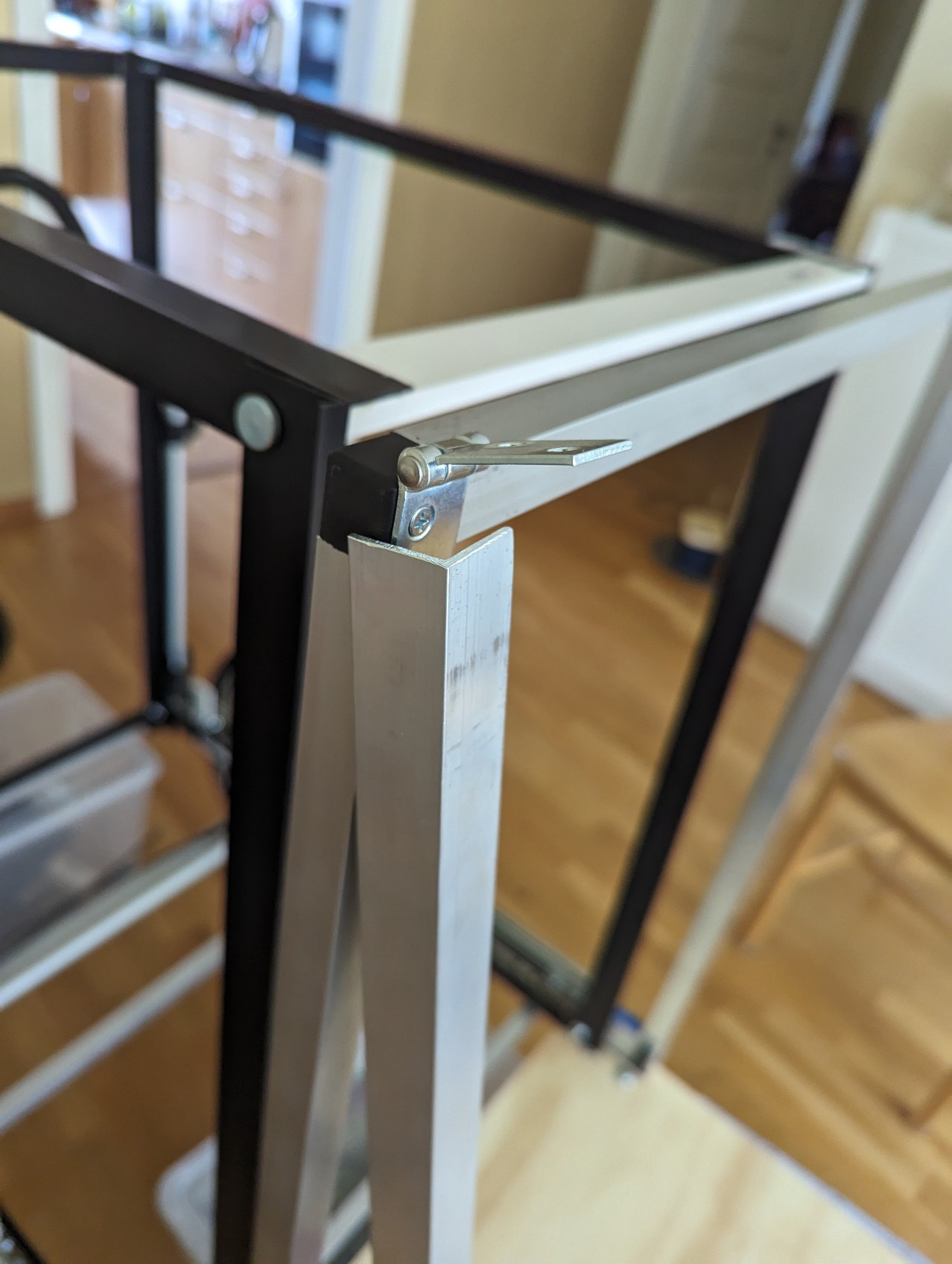
Angular fastener (Vinkelplåt) - I use both a big and a small version in the build, the big is for fastening the slider to the frame and the smaller is used later in the inside for the bed area. NOTE: The picture above with measurement is from the smaller one but the you look and work the same
My X-Fastener (X-förbindelse) used 20mm in each "corner" so I cut my pipes a bit shorter.
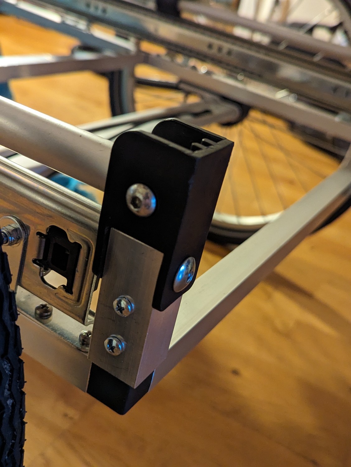
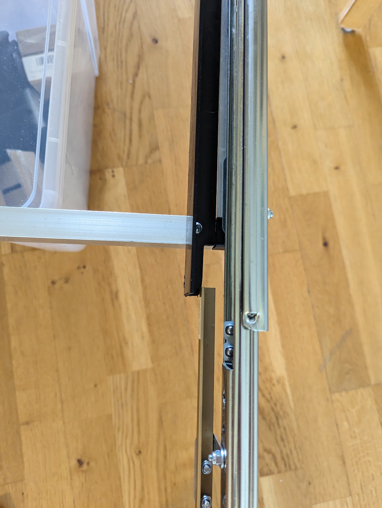
Before sawing the pipe I spend some time to figure out in what holes on the slider to put the angular fastener (Vinkelplåt) and if I should use left or right version against the frame pipe to make it work compared to the wheelbase and middle "bar". I also decided the needed space behind the slider for the handle (30mm). I ended up using a mix och left and right version on each side to make the fastening points end up in "clever" places. In the front I place backwards to make sure I could have a shorter frame. Going from front to backwards I used made the first point backwards (as mentioned), then front, front and the last backwards, but this depends on the holes on your selected slider, the wheelbase and where you place the middle bar in the frame. I also wanted to make the fastening easier by trying to get them into the plastic of the X-Fastener (X-förbindelse) as much as possible where I could just use a wooden screw. There is picture a bit below.
In my case I ended up with this:
For the length I made two of the following setup (from front) L-shape X-Fastener (X-förbindelse) , 300mm pipe, T-shape X-Fastener , 365 mm pipe and last a 3 way X-Fastener (20+300+20+365+20=725mm) .
And for the sides I made 3 x 575mm pipes (20+575+20=615mm).
I then used a rubber hammer to make the pipe and the X-Fastener (X-förbindelse) stick together.
NOTE: I first didn't use the X-Fastener (X-förbindelse) 3 way corner at the back but a L shaped one, later I replaced it with a 3 way one but some pictures are taken from the initial assembly. (Sorry about that)
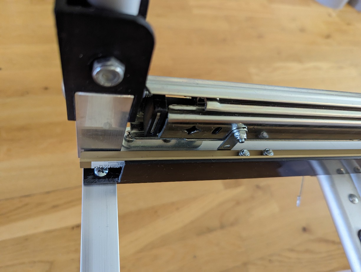
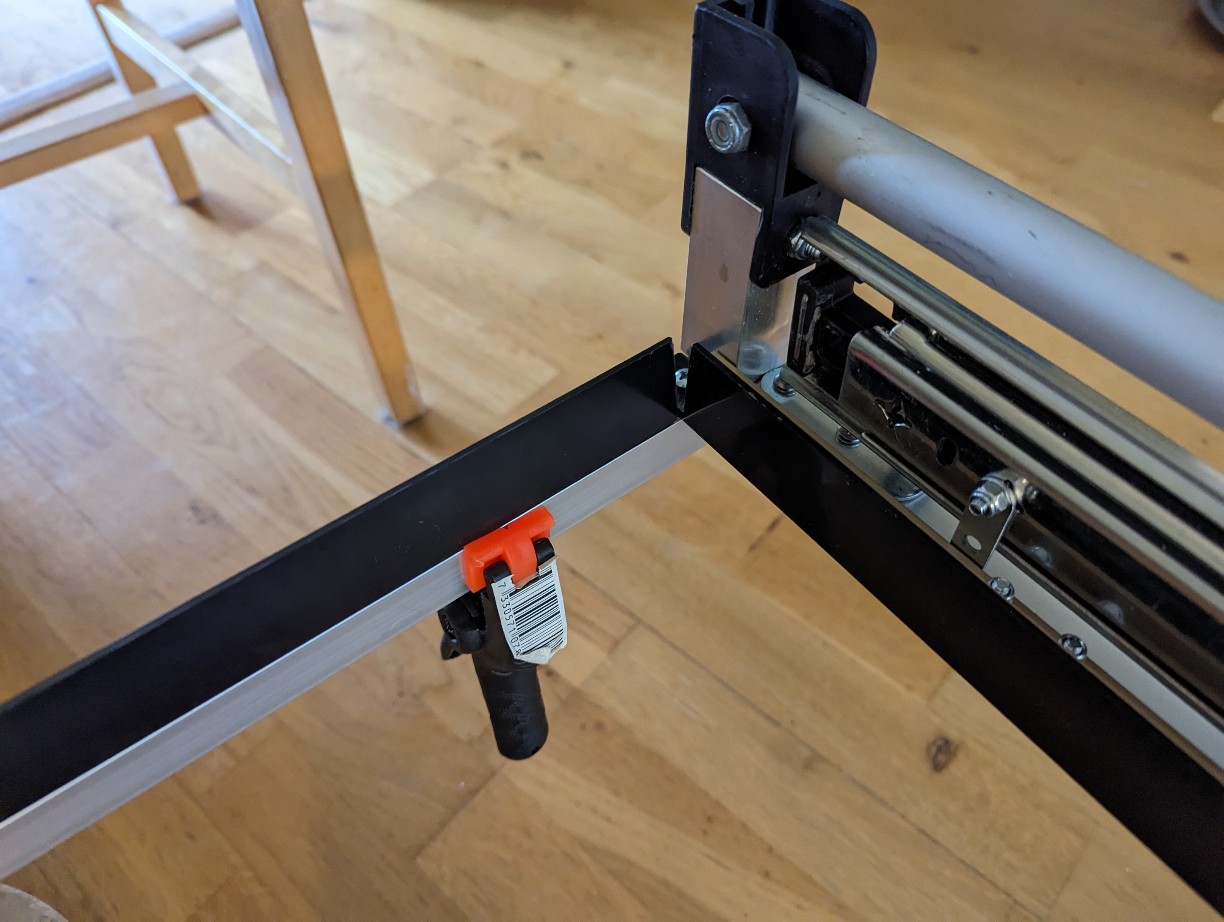
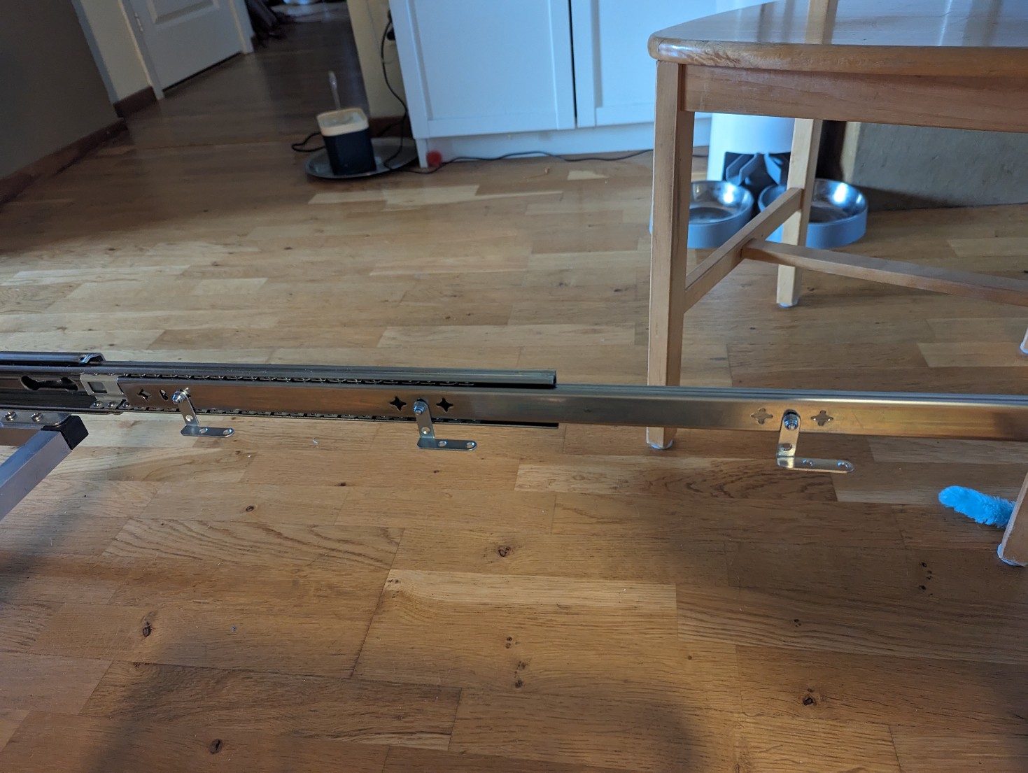
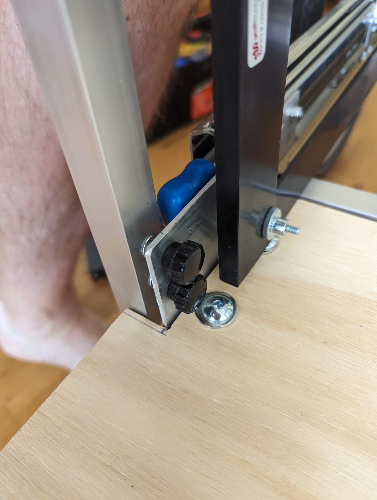
Then I fasten the slider using the big Angular fastener (Vinkelplåt), as mentioned before a lot of planning was done to get them near but not in the way from the X-Fastener (X-förbindelse), middle beam, wheel base and also the front part of the wagon to be able to build a plaform in front of the slider. To fasten it on the places where they where near a X-Fastener (X-förbindelse) I just used wooden screws (4.2mm and predrilled 3.5mm hole) Only one pair ended up not over a X-Fastener (X-förbindelse) and for it I used a M5 rivet nut tool that I got for the project, but you could also just drill all the way trough and use longer screws with a normal nut.
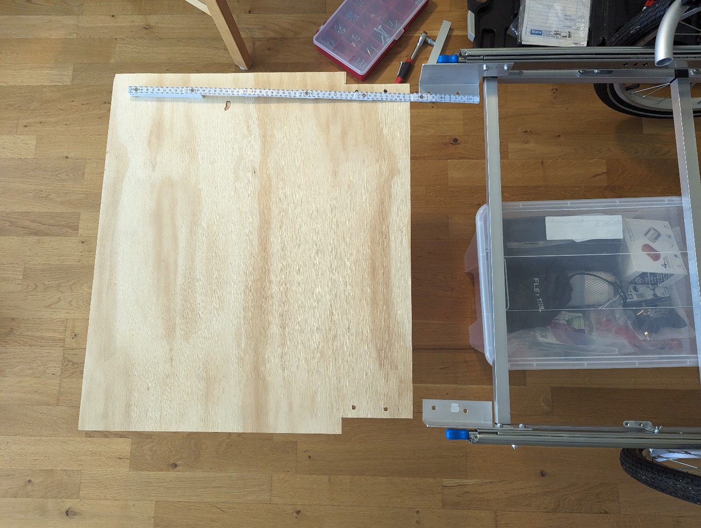
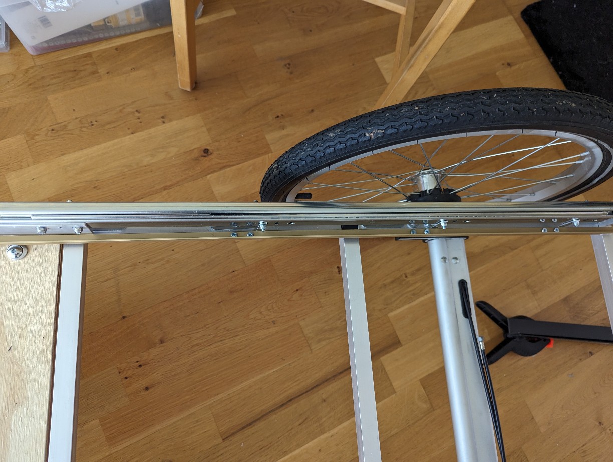
I also drilled and fasten the wheel base so the wheel rotation center ended up 260mm from back, I hope this will be good but unfortunately I have a hunch that it would be better to have it even further from the back to have a better balanced wagon, but we will see.
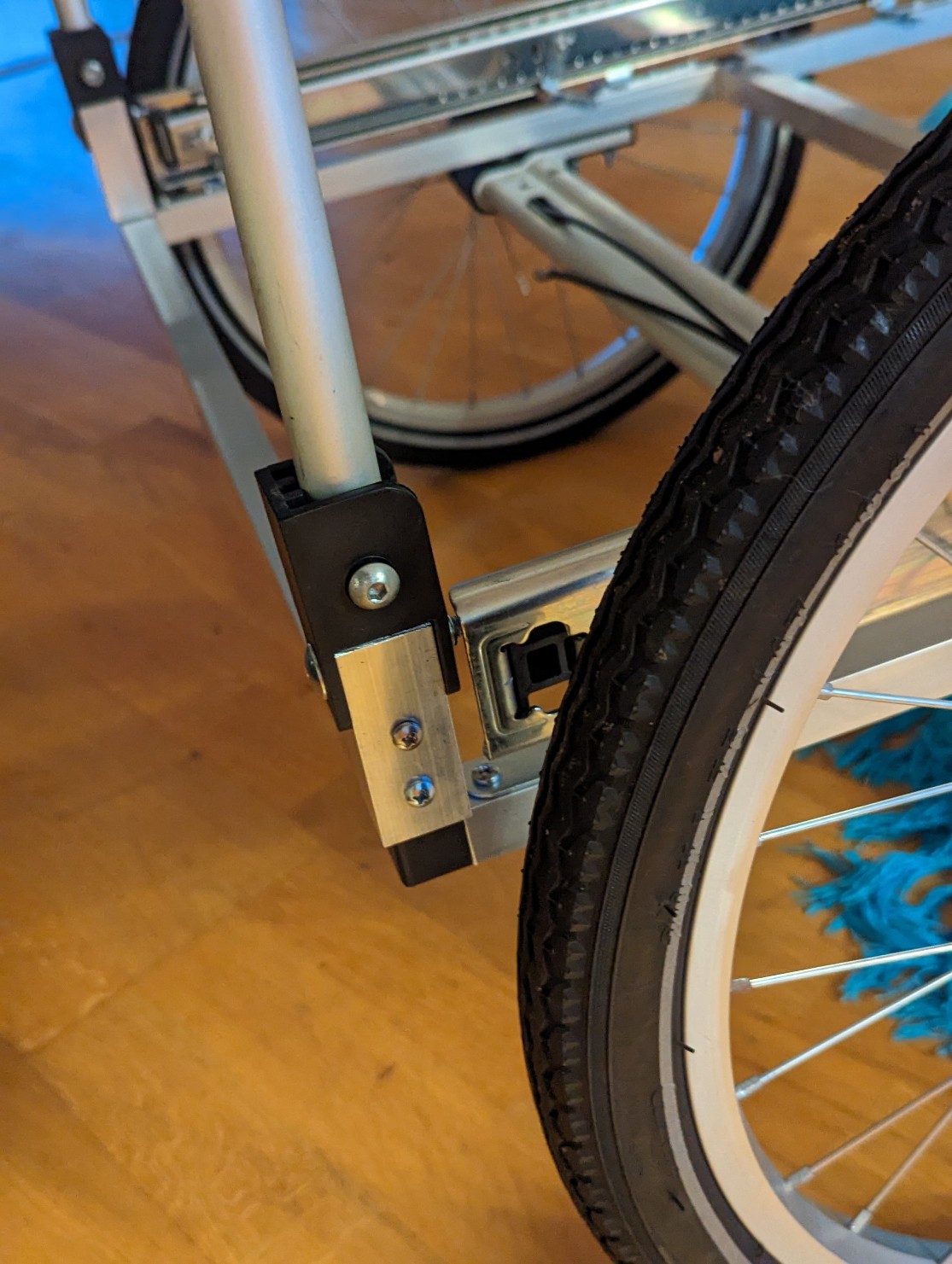
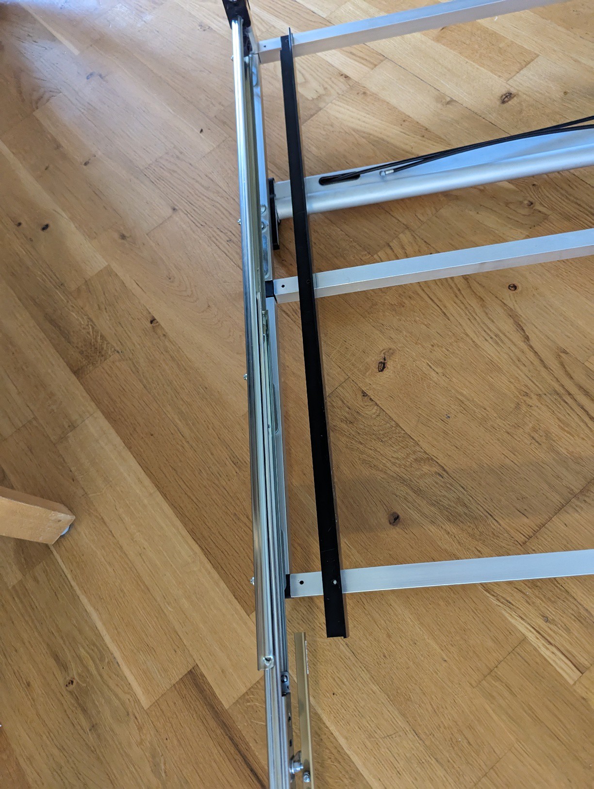
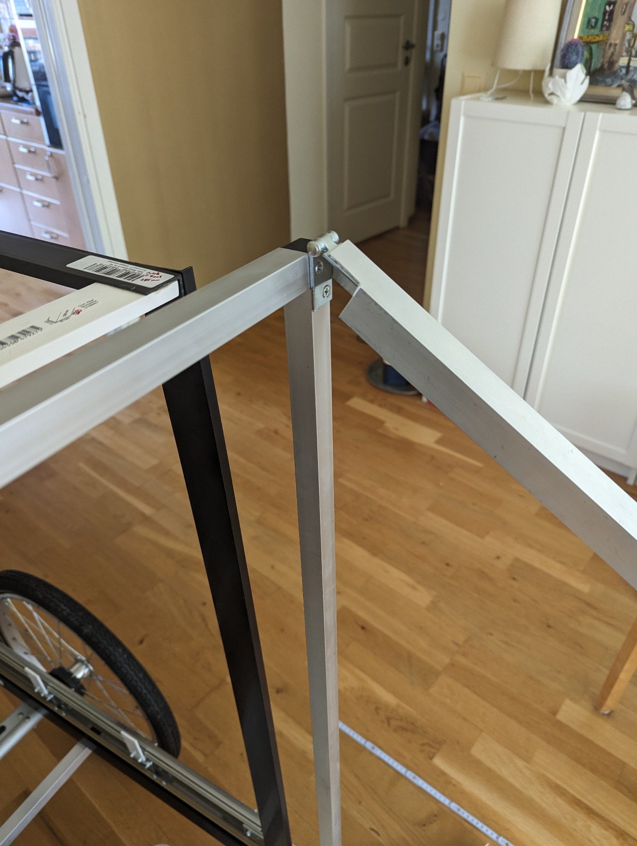
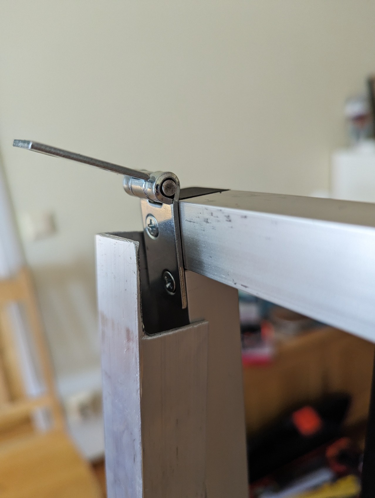
Here is a picture of the frame with the X-Fastener (X-förbindelse), wheel base and Angular fastener (Vinkelplåt) on it. I hope this picture clears up some of the description above.
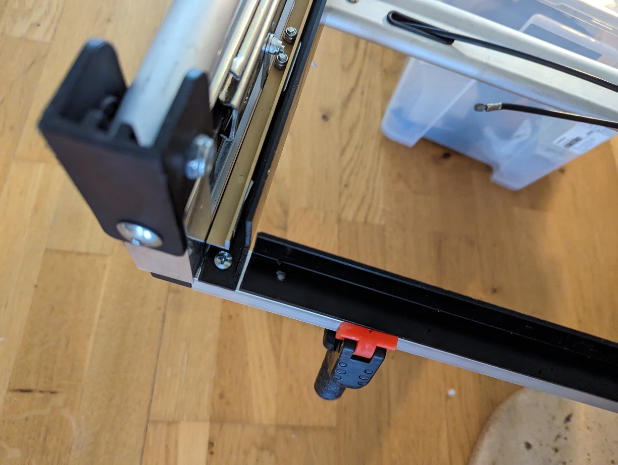
On the back behind the slider the handle will be fastened. I initially was going to just put some square pipes and figure out how to fasten the handle I had. But I discovered that I could also take the pipe the handle was fasten to from the broken wagon together with some nice plastic end caps that will make them foldable. Then endcaps was fasten to a 25x25 square pipe on the original wagon so I fasted so short (65mm) 25x25 pipes on the X-Fastener (X-förbindelse) 3 way corner with some wooden screws (4.2mm and predrilled 3.5mm hole) roughly like this:
I added a 20x20mm pipe in between the X-Fastener (X-förbindelse) and the 25x25mm pipe but that was unneeded and if I redo it Ill remove it, the wooden screws holds it firmly enough.
The 65mm long 25x25 pipes was measured to make the pipe fold down perfectly right above the slider.
I fasten the slider to the Angular fastener (Vinkelplåt) using M5 screws with flat heads. Now the frame is ready!
I don't trust that the X-Fastener (X-förbindelse) would not slide out during usage later so I will add an extra screw for each pipe where there is none already, but I will do it in the end to leave room to move stuff to make the slider operate smooth if something ends up a bit "not perfect", then I can make some small adjustment by moving the frame pipe on the X-Fastener (X-förbindelse) slightly. BUT do not forget to to it in the end.
3
Front platform
The front platform is a about 500mm long in front of the slider. The idea is that the front can be opened and one can access the stuff inside, plan is also to make this a way to climb into the wagon and a place to sit and rest or eat on the road.
I also wanted to see if I could make the front non square so that is also a big reason for using 750mm sliders and adding this platform infront outside the sliders compared to just using 1000mm sliders and having a much easier design. I also want to be able to detach this fairly easy for transportation.
Main material
Aluminium L shape 65x35x2 2x150mm
Plywood 615x530x15 (I had this at home but less thick probably work)
The plywood needs be fastened to the inner area of the slider in the front screw holes. The plywood should stick out about 500mm in front of the slider (or the length you want for the living area. The problem is that the frame is in the way AND the inner part of the living area will end up inside the slider, e.g. from the inside
Inner, "back" living area, fasten to the frame e.g. not moving.
Outer, "middle" living area and "front platform", fasten to the inner sliders e.g. moving
Slider, outside fasten to the frame, inner part moving, outside part not moving.
So the plywood needs to be below it the Inner "back" living area when not slided out.. (If this description didn't make sense it might be good to re-check this after reading further down)
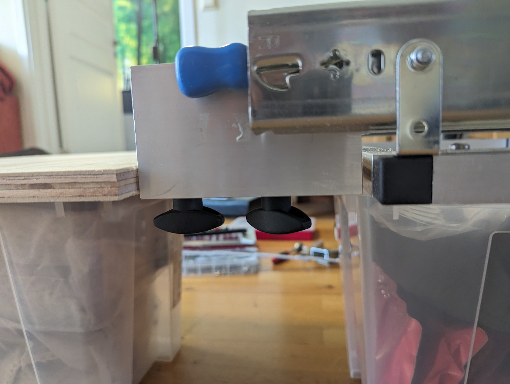
I didn't find any thing good to buy to solve this. But fortunately it will be quite easy to solve it by making our own fastening bracket. Using a aluminium L shape beam 65x35x2mm and sawing it 150mm long and saw a jack so the 65mm side can be fastened in the slider but the 35mm side can be below the inner area. Like this:
I made it so the plywood will end up at the same level as the frame. I'm not sure if that will be good or bad but remaking new brackets will be easy if needed.
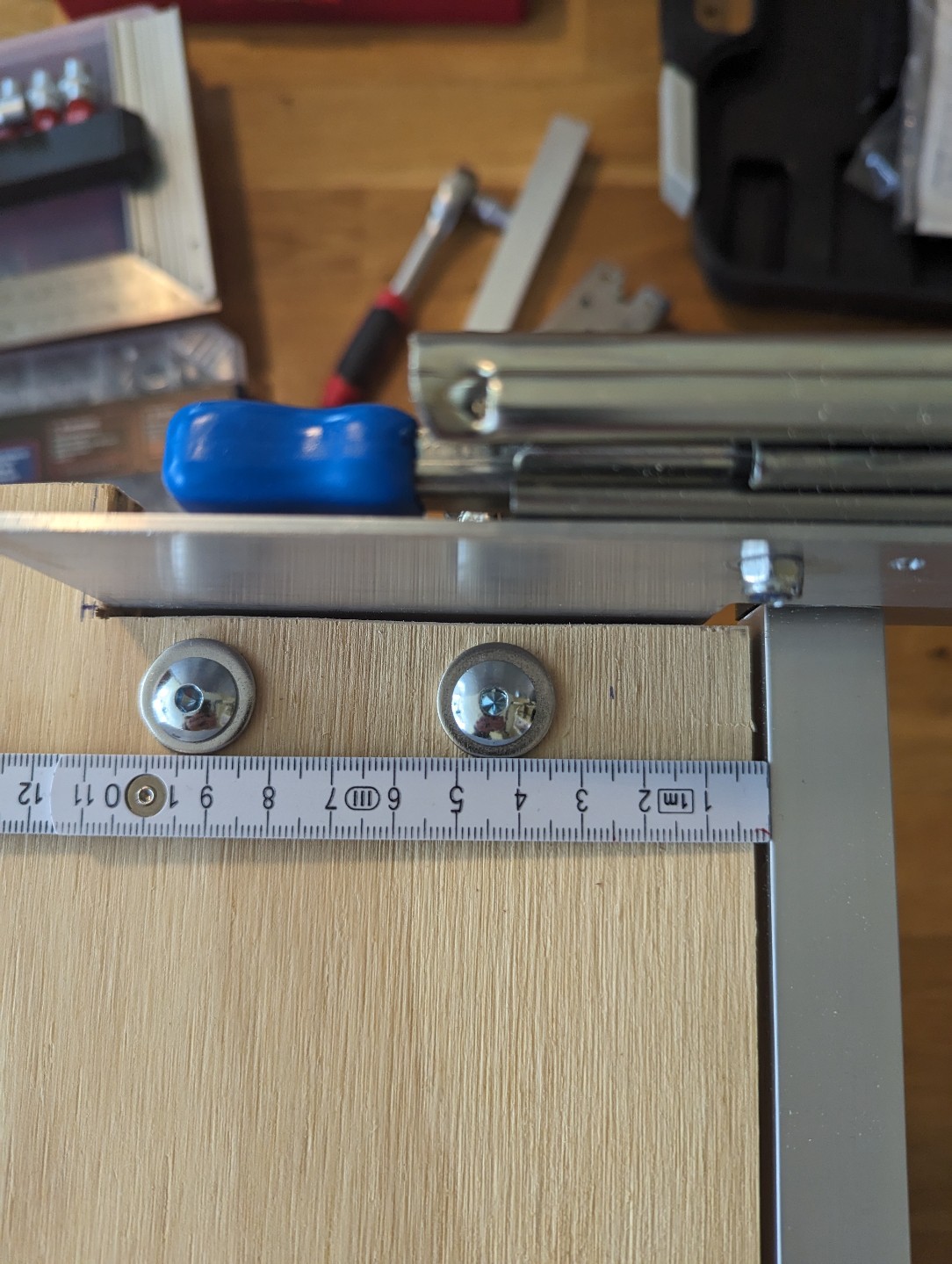
I saw jack in the plywood to match the brackets and drilled two 6.5 mm holes into plywood and the brackets to fasten it.
I used 4 x M6 screw with a flat head and fasten of with a bigger hand tight-able nut so I can disassemble/reassemble it easy for transportation. I found quite fancy ones but a wing nut would probably work equally god.
I didn't put the screws too tight to the frame as I might add legs her, we will see.
As making the fastening angular thing turned out quite easy I could have made my frame go all the way up to the length of the slider. That would make things much more easy. If you do it in your build let me know how it worked out!
4
Lower fastenings - middle bed and capsule/habitat fastener
The aim for this step is to provide lower support for the living area to rest on. For the back living area this will be placed inside the sliders fasten to the frame. The middle living area will be fasten around it and fasten to the slider (so it will slide out). The reason the outside slides out and not the mode easy to build inside is for a few reasons
I want to add stuff to the walls in the inside. Maybe have a small area and a hatch on the back near the handle so I can access stuff both from inside and outside the wagon.
Try to make most of the airflow from the front go around the wagon and not being pushed inside it.
Main material used for this step
PVC L-beam 20x30x2mm (for "back" inner area) fasten to fram
2x Aluminum L-beam 725mm long 10x10x1mm (for "middle" outer area) fasten to slider with:
6 x The small angular fastener (Vinkelplåt) (to fasten the aluminum L-beam 10x10x1mm )
TBD
5
Front wheel
16" front wheel
For this build I used an normal 16" extra jogging front wheel for bike wagons but It's basically just a normal 16" wheel but with a bit longer fastening screws so it can be fasted to a 25x25mm square pipe instead of a normal bike front wheel frame.
TBD Plan to fasten it with 25x25 square aluminum beams on the plywood but might need to be fasten to the frame also for extra stability, it also need to be somewhat easy to add and remove it and use the extra front wheel instead to save space, but we will see how it turns out.
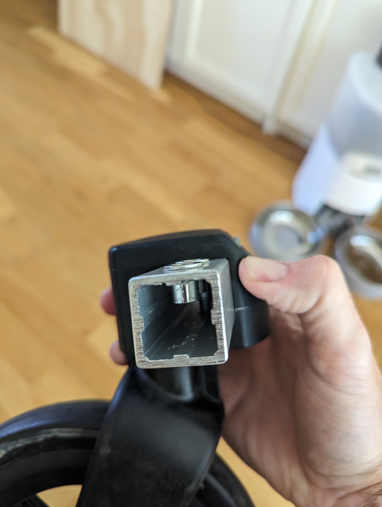
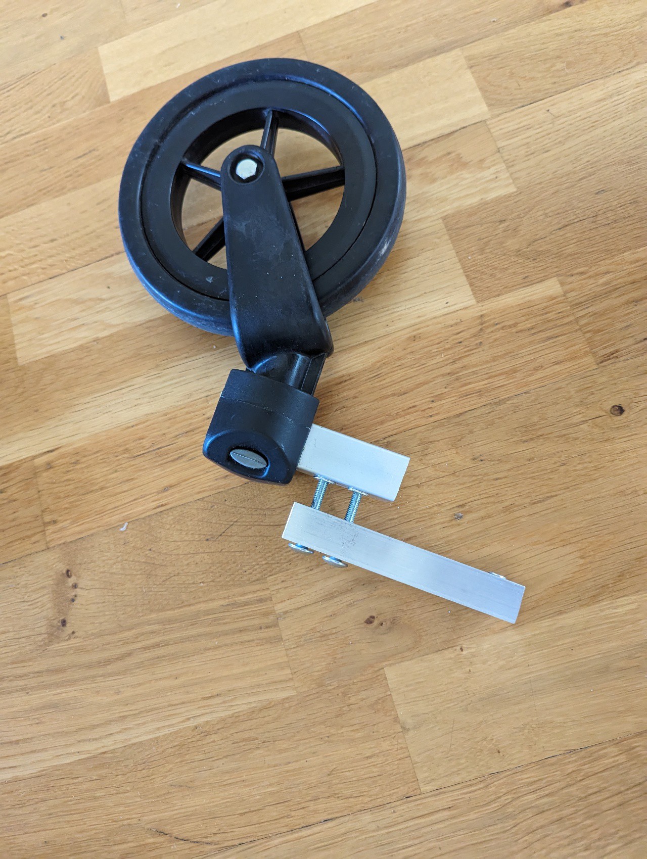
Extra freewheel
I had an detachable freewheel from another wagon that was fasten to the arm used to connect the bike wagon to the bike. I cut he arm before and after the wheel fastening and drilled two holes and added a two M6 rivet nuts (but you can drill all the way trough and use loner screws). I used a short square metal pipe as distance to be abble to access the release button so the wheel can be removed and attached easy. I then fasten it in the bottom plywood with long M6 screws so the wheel ended up as far in the front as possible but not sticking out over the edge (so that it don't take space in small spaces) and centered in the middle of the wagon.
6
Legs
TBD
Plan to use 25x25 square aluminum beams, but we will see. Legs should be fordable, and higher the the wheels to take all the weight when sleeping, and also to get the living area a bit higher and easy to sit/enter/exit.
7
Front holding structure
The front will open frontwards using a 20x20 square aluminum frame as door frame and the front part on hinges fasten between it and two U shape 25x25 aluminum beams (one on each side) The idea with the U shape is to make sure rain and wind do not enter the living area. On the two U shaped beams a skeleton construction to reassemble the front of a Citroen Hy bus is created using plastic (PVC) L shape 30x20x3mm beams and 3D printed corners (more about that in another build step)
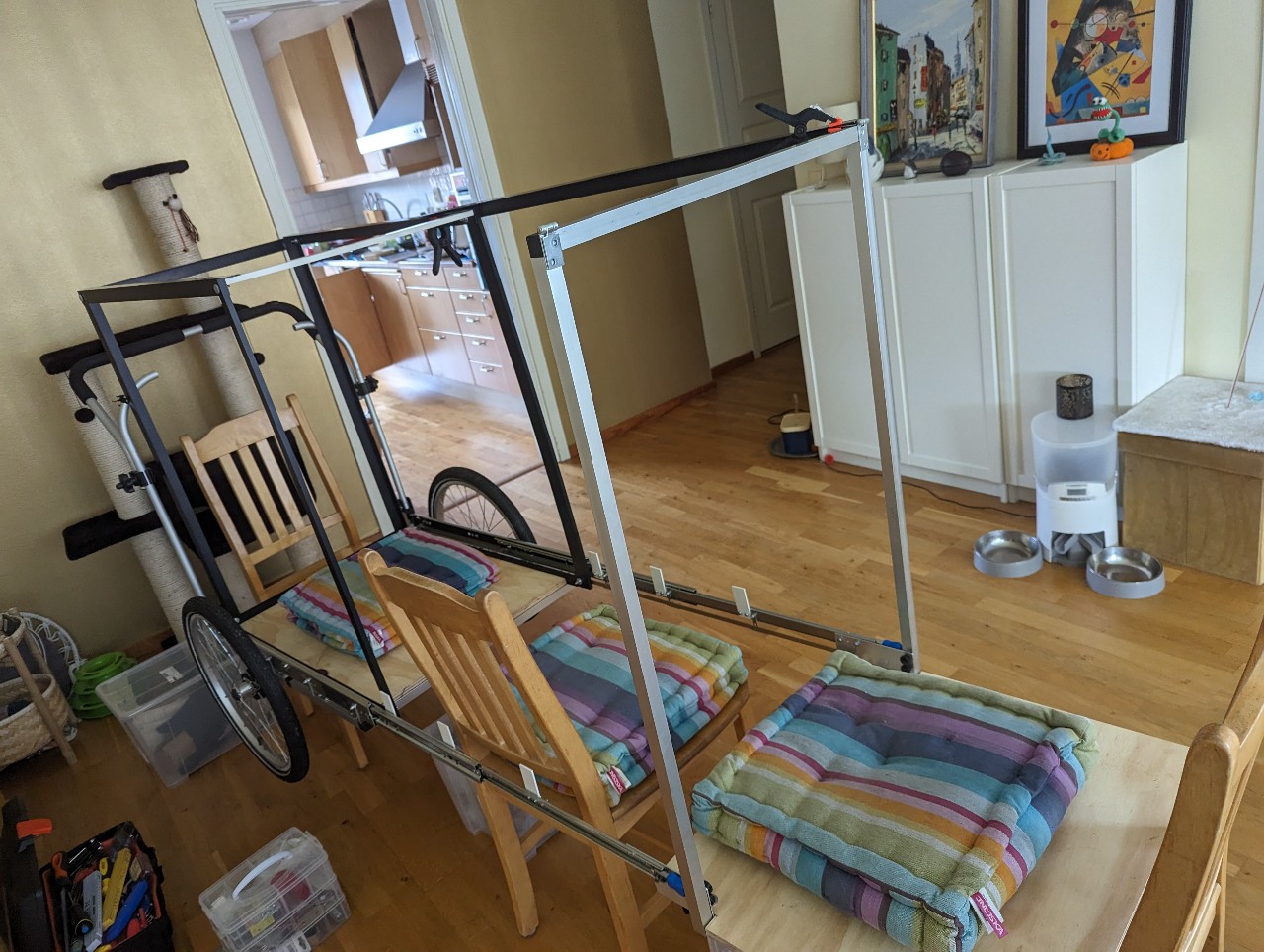
First the front door frame is created using the same aluminum 20x20 pipes and x-fasteners as used for the frame before. this frame is fasten ... The hight was used to 900mm
I use two M6 screws to fasten this on each side lite this:
Front holding structure is in place
The front will be fasten with hinges to a U shape aluminium beam slightly larger then the holding structure to (25x25mm) to make the door more water and wind prof. The aluminium beam will cover the structure. (some holes had to be cut out on the inside to make it fit)
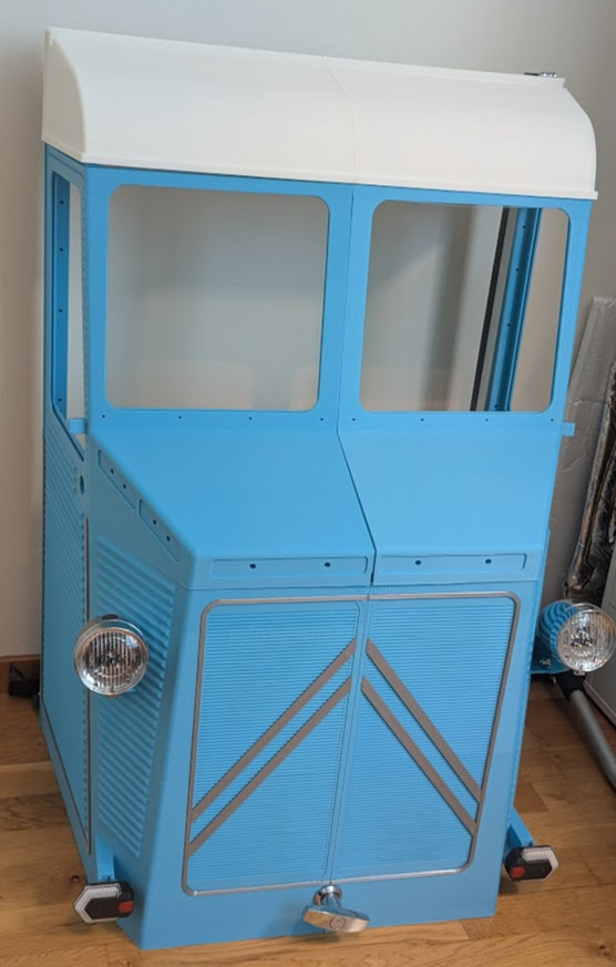
Print the files, you need at least 420x420 print bed size. I have printe most of it on a SV08 Max, I used sky blue (Elegoo PLA Sky Blue) for all but the roof part where I used white (Elegoo Rapid PLA+ White)
I have not decided it I would like to be able to open it both on the middle and also the whole front so the CAD is prepared for both. There are holes for M4 inserts from Ruthex on a few places along that should end up againts the U25 beam, I ended up using 4 on the lower part. Use M3 for fastening left and right sides and top part and side windows holder, there are quite many holes use how may you like. I have also prepead a lot of extra M3 holes here and there for future fastening of stuff if needed so I do not need to reprint the whole thing. For left/right and white root to blue front window pices I used M3 12mm lenght and glue is used for the smaller parts platics parts like the "chrome/silver" around the door and the front.
I bought precut 2x 250x250x2 acrylic sheets for the two front windows and a 400x300x2 sheet to the side windows that need to be cut. (not done yet so I hope it works)
9
Middle / Back Living area
TBD The idea is to create 2 shells the when you open the wagon will create a long area. The back one is made a bit smaller to fit inside the one in front like a drawer. The back one is fasten to the base inside of the sliders and the outer will be fasten inside of the slider making it work like a drawer.
The idea is that you can open the front and crawl in. I also plan to see try to make some sort of door on the side, it would be more easy to use and less stressfullt on the structure as there will be less moving around in the wagon, but lets see.
10
Bed area
TBD The plan is to have a fixed floor in the back and front sections as it will not move when opening. For the middle section a hole will appear when dragging out the wagon and the plan is to have 2 trays I can lay down here that will rest on the two 725mm long aluminum L-beams 10x10x1mm on the fram.
The idea is to add sleeping mats (one thick or 3-4 layers of normal XPE - Sleeping mat) on the area. One idea is that the 2 loos trays for the middle section can be removed from the inside so you can sit normaly inside the wagon and maybe access the compartment undet the wagon from inside if needed, A wilder idea is create a tube that goes down to the ground where you can have the feet in if it reains and also put packing/water and other stuff while sleeping. But lets see :)
 Zingo Andersen
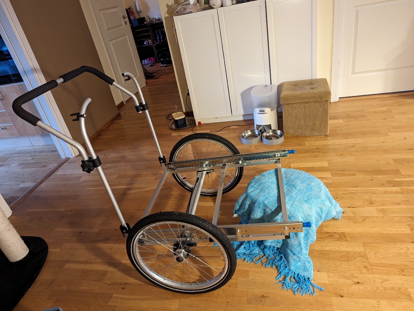


Discussions
Become a Hackaday.io Member
Create an account to leave a comment. Already have an account? Log In.
Thanks a lot! I hope the instructions makes some ense and some ideas can be useful and inspiring or solve something for somebody 😊
I hope and will try to keep this updated during the build.
Are you sure? yes | no
Thank you for sharing this information and your experience!
Are you sure? yes | no