0%
0%
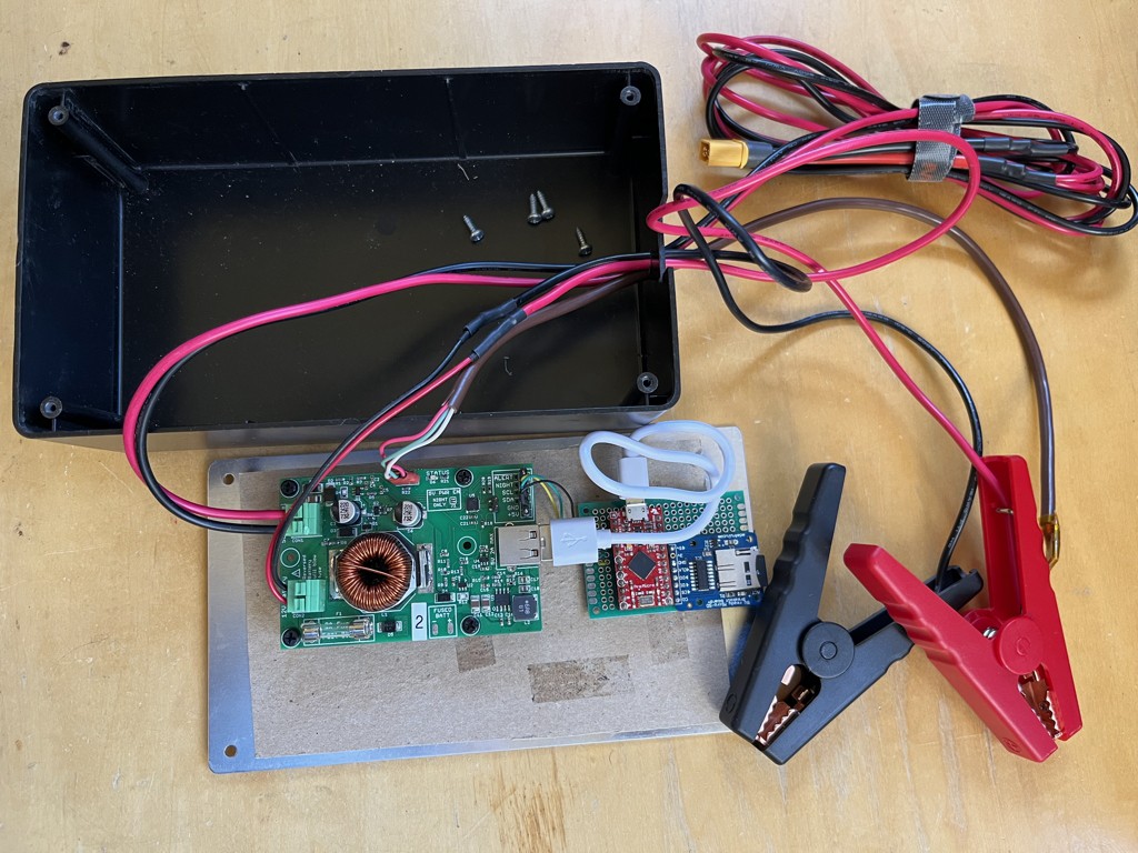
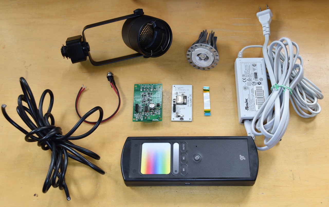
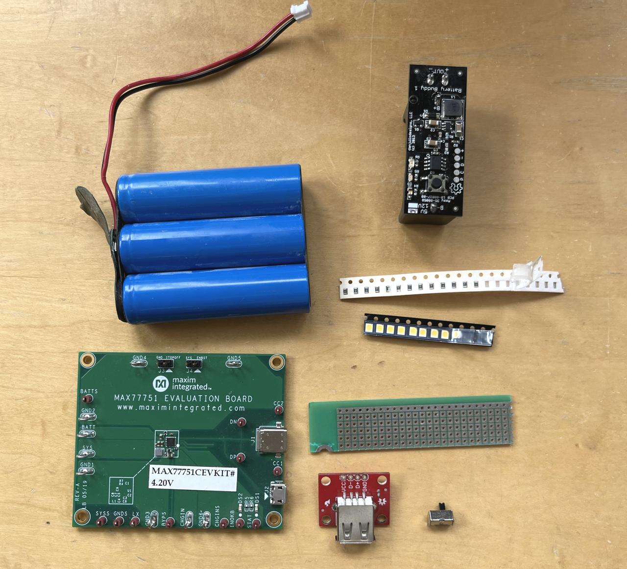
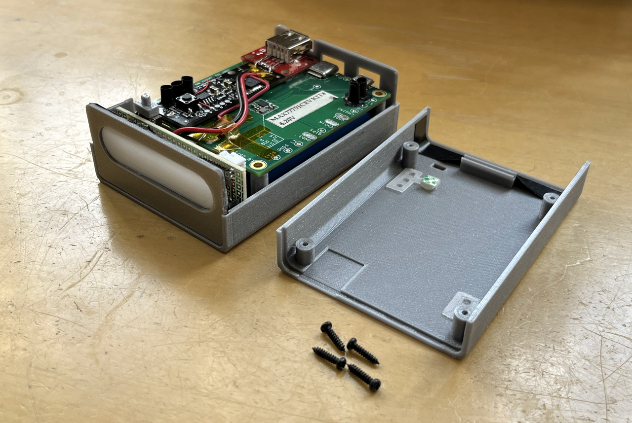
Use It Up!
Documenting my efforts to use up the various electronics bits and pieces I've collected over the years.
 Dan Julio
Become a Hackaday.io member
Already have an account? Log in.
Just one more thing
To make the experience fit your profile, pick a username and tell us what interests you.
Pick an awesome username
hackaday.io/
Your profile's URL: hackaday.io/username. Max 25 alphanumeric characters.
Pick a few interests
Projects that share your interests
People that share your interests


 Jon Kunkee
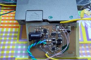
 Kumar, Abhishek
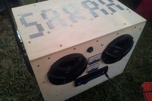
 Doubleyou
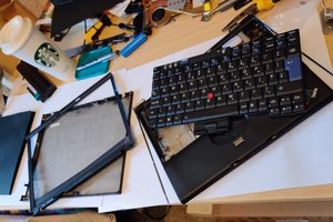
 Sean
Sean
Love this idea! Subscribed. :)