COMET68k
My take on a highly integrated, Motorola 68000 based "single" board computer.
My take on a highly integrated, Motorola 68000 based "single" board computer.
To make the experience fit your profile, pick a username and tell us what interests you.
We found and based on your interests.
It has been a while since I last provided an update, and there have been a number of developments and interesting things in that time!
Following my previous update where I had identified several changes that were due for revision 2 of COMET68k. In November I ordered the PCBs with high hopes for resolving a number of issues outstanding from revision 1.
To address these points:
There were some minor issues during construction, namely some pins which did not reflow on some parts. This is probably an issue with my placement technique and maybe the fact that I use a lot of "new old stock" parts that may not have necessarily been stored correctly over time and whos pins are less receptive of solder. Most of the issues were on the Ethernet controller, with a few pins also requiring some touch up on the CPLD, and one pin on the CPU. Technique wise, I probably need to press the components down into the solder paste rather than simply sitting them on top of it...
As of writing I have identified a few more things which could constitute a 3rd revision, however, I do not currently know whether I will actually build a 3rd revision or move on to a more capable (e.g. 68030 based) system.
An early goal of COMET68k was to port FreeRTOS and its TCP/IP stack to my board, and I've managed to achieve this goal. For TCP/IP performance, in my testing I was able to achieve upwards of 200pps or about a megabit of throughput when running a ping flood with various packet sizes. I feel like that is quite reasonable for a 10MHz processor doing almost everything in software (the only "hardware acceleration" being packet transmission and reception handled through DMA by the Ethernet controller).
At the moment I maintain my own copy of the FreeRTOS kernel including my port on github, but I plan to publish this to a repository managed by FreeRTOS themselves which contains community maintained ports. I feel this will be a much better place for this port to be housed, so keep an eye on that for my latest port (which is much enhanced over the port I currently have published). Whether the FreeRTOS+TCP port can also be maintained here is something that I need to determine.
While my original (stretch) goal was to get something like uClinux running on my board, this feels a bit beyond my capabilities for the time being.
So instead, over the christmas break, I put some effort in to making CP/M-68k work, and I have written a BIOS to work with my hardware. Although it is a somewhat simplistic OS (compared with a modern MS-DOS for example), it at least provides something for me to work with and test out some of the expansion hardware that I have built, and will provide a platform for testing additional hardware (and software!)...
Read more »In this post I want to go over the architecture of COMET68k in some more detail. Specifically I'll describe the busses that exist, which peripherals are on them, and how they function.
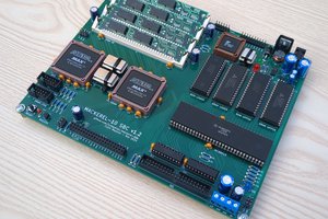
COMET68k is an enhanced collection of peripherals integrated onto one PCB, enough to make a rather capable standalone or single board computer (if all you care about is serial for input/output). These peripherals are connected to two basic busses, with a 3rd bus providing expansion capability:
All of the above busses relate to the data portion of the bus. The address bus is largely singular, except when it comes to the expansion header where most signals are buffered in some way. One address signal is synthesised from the upper data strobe to produce XA0 for the X bus to permit 8-bit devices to be readable and writeable on sequential addresses.
Here is a diagram showing how all of the peripherals fit in to these busses:
The local bus is the bus which is directly connected to the CPU. Its a 16-bit wide bus connecting directly to DRAM, the ethernet controller, the X bus buffers and latches, and buffers for the system bus. The CPU and ethernet controller can both be bus masters, and therefore have direct 16-bit access to DRAM to read instructions and data. This is particularly important for the ethernet controller so that it can DMA packet data as quickly as possible to and from DRAM during transmit and receive operations.
I chose the Am79C90 ethernet controller specifically for its capability to work directly from memory (also known as "zero copy") as this removes the need to copy packets to and from FIFOs or RAM internal to the ethernet controller itself. Although it complicates the system design a little bit, it helps improve performance.
I refer to this as the "cross" or "X" bus because it allows 8-bit peripheral data to be directed to or from either half of the CPU local bus. The X bus houses all 8-bit peripherals such as the RTC, UARTs, and some GPIO to allow control of some status LEDs, ethernet loopback options, and reading of configuraiton jumpers and other status bits. It also houses both of the ROM sockets that the CPU executes code from.
As I mentioned in my first post, I have implemented a technique which permits execution of code from a single 8-bit wide ROM, despite the CPU having a 16-bit interface. This is achieved using a latch and buffer which, when directed appropriately, can enable a 16-bit value to be read from the ROM and presented to the CPU. The idea is shamelessly borrowed from a HP JetDirect print server card that I bought in a rummage sale. But I want to give you a more detailed look at how it works, and I think an (annotated) timing diagram is probably the best way to do this with a bried explanation of a 68000 cycle (you can click the image to access the Wavedrom website and view the source of this diagram).
At the falling edge of CPU state S0 the CPU asserts an address on to the address bus (a), arming address decoding circuitry.
At the rising edge following S1 the CPU the CPU then asserts its Address Strobe signal to indicate that the address is valid (b). This then causes the ROM chip select signal to be asserted (c) and it starts outputting data for the lower byte of data.
At the next negative edge of the 40MHz clock the X bus state machine has started to assert some of the control signals required to interface the X bus to the CPU local bus, in this case allowing the contents of the X Data bus through to the lower half of the CPU local bus (d) via a latch. It then proceeds to implement a small delay to satisfy the access time of the ROM.
At the end of this delay several things happen at marker (e):
The story of COMET68k really starts back in July 2021.
I had introduced a friend to the Motorola 68000 CPU and he was in the process of designing and building his first project using one of these processors. During the preceeding couple of years I had been reading the 68k's documentation during my commute to work since it was a good way to pass the time, so I was able to help him figure out the logic and explain how things worked.
Throughout this I developed enough of an itch to design and build my own 68k based system as well, something I had been wanting to do for a while, but hadn't yet started because I was consuming my time with some other projects (coincidentally 68k related so my head was already firmly in this space: Cisco 2500 Series Reverse Engineering and Cisco 1600R Series Reverse Engineering).
My first design was fairly simple - it could act as a standalone system with ROM, RAM, and a UART on board, but I also added some expansion slots that would allow additional functionality to be added. I had grand visions to add an ethernet controller and some kind of home brew video card. But I had also designed in something of a fatal flaw: there was no way for anything other than the CPU to be the bus master.
So after building a couple of plug in cards for this system (including a prototype VGA card) and reaching the point where I really wanted to start work on an ethernet controller for it, but considering the controller I wanted to use would not be able to take over the bus to DMA packets to/from memory, I started to think about what I should build to replace it. I had a VMEbus backplane sitting around that I was eager to do something with, so building a Eurocard style system was high on my list of candidates.
It would be about a year later when I was at EMF camp 2022 that I finally got my inspiration for what my new system should look like. There was a rummage sale at EMF camp, and in it I found an old HP JetDirect print server card which had a Motorola 68EC000 and Am79C90 ethernet controller on it (the same one I had already worked with in the Cisco 2500 reverse engineering project). I was impressed with the form factor, being not too dissimilar to a 160x100 Eurocard style board. It also had a neat trick up its sleeve which I decided I would try to copy on my new system (more in a moment).
I had begun to travel a lot for work at this stage, mostly by myself, and not being much of a "going out" kind of person I needed something to keep me entertained during the evenings in my hotel room when all I had was TV in a foreign language that I couldnt understand. So I set about putting together a schematic for what would become my new system.
I decided to be a bit ambitious with this design, it would be a "high risk, high reward" design - the potential for failure was increased, but the reward if it all worked would be huge. Several months of on-and-off work on the schematic produced a design which I really liked, and was certainly very ambitious. I was going to attempt a design with a bunch of things I had never successfully used before, in particular DRAM, but also the ethernet controller. But the most unique feature, and the one that I was sure would cause the greatest potential for failure, was the trick that I borrowed from the HP JetDirect card.
I had originally intended to reverse engineer the JetDirect card and try to make FreeRTOS run on it, since that was my favourite thing to do with 68k based systems, and while exploring the hardware and the way it was connected I discovered something very interesting. Although there were two ROMs on the board (not unusual for a 68k system with a 16-bit data bus), the two ROMs were wired entirely in parallel. "Ok, the 68EC000 can run in 8-bit mode..." I thought, but when I investigated this more closely I discovered that the CPU was configured...
Read more »
Create an account to leave a comment. Already have an account? Log In.
Become a member to follow this project and never miss any updates

 Dave Collins
 Colin Maykish
 Jason Westervelt
 Tobias Rathje
Nice project!