doctek
-
Using the I2C Interfaces
01/08/2026 at 20:09 • 0 commentsThings to know about I2C on WeActDuino:
- two ports are usable. I2C1 & I2C2 or I2C1 & I2C3.
- all I2C lines are 5V tolerant.
- the correct clock (SCL) and data (SDA) pins must be assigned before the begin() method is called for the I2C port.
- the I2C lines must be pulled up to the correct voltage: 1.8K to 3.3V or 5.1K to 5V. (the resistor values don't have to be exact.) Sometimes these are built into I2C peripherals, sometmes not.
- Pin 36 (B8) is the boot0 pin. If it is not floating or low at reset, then the WeActDuino won't boot. So it is best not to tie any inputs to it.
Note that although there are three ports, only two of them can be used at a time. There is only one possible pin for SCL3 and SDA2 and it's the same pin (PA_8), so either I2C2 or I2C3 can be used, but not both at once. (ST is not doing this just for marketing purposes; G431 chip versions with more pins make the third port available.) Anyway, let's see how to use the I2C ports. All G431 I2C pins are 5V tolerant and they will work fine on 3.3V also. I2C is bidirectional, so 5V pulses are returned from a 5V device even if only 3.3V pulses are sent. The pull-up voltage must match the operating voltage of the I2C device(s) being used. A peripheral device operating at 3.3V may be damaged by 5V I2C pulses.Since there are three possible I2C ports, we must declare one as an I2C object and assign the correct SDA and SCL pins before use. There are two ways to configure the I2C pins. We can assign them after instantiating the TwoWire object but before doing begin(), or we can instantiate a TwoWire object with pin assignments. Either method works. The assignment method may be required if the name of the TwoWire interface can't be passed in to the library using it. In this case, the library will use Wire as the I2C object, as instantiated in the Wire.h file. SDA and SCL must be assigned.
Examples of both methods are included. G431_72x40 uses Wire.setSDA() and Wire.setSCL() to use the u8g2 library which does not allow the I2C object to be passed in. It uses the default Wire object declared in Wire.h. G431_Dual_I2C uses libraries that allow the I2C object to be passed in. These objects are declared in the Arduino sketch before instantiating the display objects.
The Arduino files we will use go in the Sketchbook directory. Find your Arduino Sketchbook location from the Arduino IDE using File > Preferences. The Sketchbook location is the first entry in the window. Download one of the zipped archives from the Files area and unzip it into your Sketchbook directory. Then open it in the Arduino IDE using the File > Open command. You can now edit it or upload it to the WeActDuino.
72x40 display version:
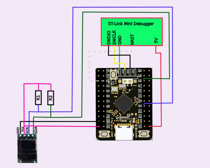
Parts:WeActDuino (STM32G431)
72x40 LCD with SSD1306 controller; I2C interface, 3.3V
2 1.8K ResistorsHook up:
Component Component Pin WeActDuino Pin Comment ST-Link Mini Debugger SWDIO DIO 4 Pin Header ST-Link Mini Debugger SWCLK CLK 4 Pin Header ST-Link Mini Debugger GND GND 4 Pin Header ST-Link Mini Debugger NRST NRST ST-Link Mini Debugger 5V Vcc 72x40 Display Vcc 3.3V 72x40 Display GND GND 72x40 Display SCK A8 (SCL3, D21) 1.8K to 3.3V pullup 72x40 Display SDA B5 (SDA3, D31) 1.8K to 3.3V pullup ![]()
Notes:Have a look at the code. Use the procedure described above to load G431_72x40. This is a simple example. The first step is to define the pins that will be used for I2C. This has to be done before calling the display initialization routine. The Wire object is instantiated in Wire.h, so sending messages to it works. There is no other way to pass this information to the u8g2 object, but this method works fine. After calling Wire.setSDA() and Wire.setSCL(), the pins designated will be used whenever u8g2 uses the Wire routines. The Wire object is instantiated in Wire.h, so the "Wire" label must be used even if the pins assigned belong to I2C3. The pin definitions must be done before Wire.begin is called. In this case, Wire.begin() is called from the u8g2 package when u8g2.begin() is called. (NOTE: The actual name of u8g2 routine will depend on name given when it is instantiated. In our case, that's "u8g2".) The actual pin numbers used are found in WeAct_Pin_Map_R1.png for I2C3. The rest of the code is from a simple u8g2 example.
Since the 72x40 display uses 3.3V, the I2C lines are pulled up to 3.3V using 1.8K resistors.Dual I2C displays version:
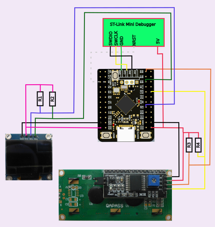
Parts:WeActDuino (STM32G431)
128x64 LCD with SSD1306 controller; I2C interface, 3.3V
16 x 2 line LCD with HD44780 controller and PCF8574 I2C Interface, 5.0V
2 1.8K Resistors
2 5.1K ResistorsHook up:
Component Component Pin WeActDuino Pin Comment ST-Link Mini Debugger SWDIO DIO 4 Pin Header ST-Link Mini Debugger SWCLK CLK 4 Pin Header ST-Link Mini Debugger GND GND 4 Pin Header ST-Link Mini Debugger NRST NRST ST-Link Mini Debugger 5V Vcc 128x64 Display Vcc 3.3V 128x64 Display SCK A8 (SCL3,D21) 1.8K to 3.3V pullup 128x64 Display SDA B5 (SDA3,D31) 1.8K to 3.3V pullup 128x64 Display GND GND HD44784 Display Vcc 5V HD44784 Display SCK A15 (SCL1,D28) 5.1K to 5V pullup HD44784 Display SDA B9 (SDA1,D35) 5.1K to 5V pullup HD44784 Display GND GND ![]()
Notes:
Two I2C displays are used. The HD44780 runs at 5V while the SSD1306 runs at 3.3V and will be damaged by operating it at 5V. Separate I2C channels are used so the lines can be pulled up appropriately. The 5V tolerance of the G431 is perfect for this application. The SDA and SCL lines for the two ports are chosen from WeAct_Pin_Map_R1.png for I2C 1 and 3.
Let's consider the software now. Use the procedure described above to load G431_Dual_I2C. We use two different display libraries as noted in the comments. Since the libraries for both displays allow the I2C object to be passed in, we first create the TwoWire objects. Then we instantiate the display objects and pass in the names of the TwoWire (I2C) objects. These names will be used in all calls to the display libraries and we need not worry further with them. Note that the SCL and SDA pins for each of the TwoWire objects were passed when the objects were created (or "instantiated"). -
Using DAPLINK
04/15/2025 at 22:43 • 0 commentsAs of 4/15/2025, I'm using STM 2.10.1 instead of STM 2.8.1. DAPLINK hardware is now supported along with ST-Link. The upload method menu allows choosing either one. OpenOCD can be used for debug also. The idea is to support debugging from the Arduino IDE. OpenOCD is required for that. Unfortunately, debug doesn't quite work for the WeActDuino yet. I'm still working on figuring that out. At least you can use DAPLINK fro uploading!
-
Digital, Analog, and Serial Capabilities
04/10/2025 at 05:04 • 0 commentsThe pins of the WeAct Duino are shown in WeAct_Duino_Pin_Map_R1.png, available in the Files section. The physical pin numbers are highlighted in green. Usually, we won't refer to them by physical number. Let's discuss their capabilities.
Digital Pins: All pins indicated in the WeAct_Duino_Pin_Map_R1.png as digital pins (highlighted in gray) work as expected except D1 and D2. These pins (C14 and C15) are connected as clock oscillator pins for the 32.768KHz crystal for the Real Time Clock module. It is possible to remove the crystal and the two associated capacitors, then install jumpers SB1 and SB2, then D1 and D2 will function as expected. Note D0,D1, and D2 all have very limited output drive and should not be used to drive leds or other moderate current loads. Since it seems that these pins are intended as inputs (pushbutton on D0) or clock drive, I can't really get excited about testing them as digital I/O. I'm more interested in using the Real Time Clock capabilities. (That will be the subject of a Project Log soon.) So just ignore D1 and D2; D0 is the user button. All digital pins can source or sink 20mA except D0,D1, and D2 (C13, C14. C15). Those pins are limited to 3mA. The total current from all I/O pins is 100mA max.
Analog Read: All pins A0-A15 (mustard highlight) have analog read capability. The default resolution is 10 bits (0 to 1023) and the input level can be 0 to 3.3V. Using analogReadResolution() allows the resolution to be set to 6,8,10,12,14, or 16 bits (all tested). Note that the setting will apply to all analog input channels. They can't be set individually.
Analog Write: All digital pins with the letters "pwm" beside them are capable of pwm output. The default frequency is 1KHz and the resolution is 10 bits (0 to 1023). Using analogWriteResolution(),the resolution can be set to 6,8,10,12,14, or 16 bits. With analogWriteFrequency(), the pwm frequency can be set from 1Hz to as high as 400KHz. Using analogWrite() with plns A4 and A5 (digital pins 7 and 8) will use the DAC so a true analog voltage level will be output. The default resolution is 8 bits and analogWriteResolution() may be used to increase the DAC resoution - 12 bits is the maximum regardless of the setting.
5V tolerance: The pins indicated with a red dot next to the pin number are 5V tolerant. This means that an input signal from a device powered by 5 volts can be use without damaging the WeAct Duino. Configure the pin as an INPUT only, do not use a pull-up or pull-down. Providing a suitable 5V output is less of a problem. A 3.3 volt output is a sufficient 5V high input, so no pull-up is usually required. If one is needed, then use OUTPUT_OPEN_DRAIN and pull up to 5V to control the 5V peripheral. Any digital pin can be used like this.
External Interrupts (digital pin interrupts): External interrupts are described here. An Uno has two external interrupts; but the WeAct Duino has one available on every digital pin. There are two restrictions. The first is that only 16 total external interrupts are available. (That's still a lot!) Although any digital pin is a potential external interrupt, the rule is that pins having the same physical pin number in different ports conflict (like A5 and B5). They get mapped to the same EXTI line. Only the last one used by attachInterrupt() will actually cause an interrupt. There is no compiler warning of this behavior. Refer to WeAct_Duino_Pin_Map_R1.png for the physical pin numbers. The only modes supported by attachInterrupt() for the WeAct Duino are RISING, FALLING, or CHANGE, not LOW or HIGH. It is unnecessary to use the digitalPinToInterrupt() function, just the digital pin number is enough for attachInterrupt(), but you must be aware of the physical pin number to avoid possible conflicts.
Serial I/O: Using the USART (serial) capability of the WeAct Duino is actually pretty easy. All that's required is to instantiate a HardwareSerial object (call it mySerial, for example), and use it as you would use Serial in an Uno sketch. When you instantiate the HardwareSerial object, find the pin numbers to use from WeAct_Duino_Pin_Map_R1.png. Specify the digital pin numbers, Rx first, then Tx. The other necessary step is to select "Enabled (no generic 'Serial')" from the Tools / U(S)ART support menu. It is not necessary to #include HardwareSerial.h to support the serial capability. Note that the pin numbers you pass in will determine which of the five available USARTs will be assigned to the name you use. For example, pins 23 and 24 will cause USART 1 to be used (the Rx pin is first, then the Tx). Make sure you pick Rx and Tx pins that are on the same USART. Now you can connect to Tx and Rx with a serial to USB interface, use the one provided with the WeAct ST-Link, or connect to another serial device, such as a GPS receiver. There are 5 serial ports available: 1,2,3,4, and L (Low Power). While the Low Power Serial port has some special properties, you can just use it as a standard serial port. If the device you connect the serial port to runs at 5V, be sure to select serial port inputs (RX) that are 5V tolerant.
Example using External Interrupts and Serial output: Time for an example or two to really see how serial and external interrupts work!
For this example, we'll use the HC-SR04 ultrasonic distance sensor. If you're not familiar with it, have a look here. You'll find a good explanation of the HC-SR04 and how it works, and an example program for an Uno. Stop reading when you get to the "Arduino Ultrasonic Sensor and LCD Display Example" part. We aren't using an Uno, nor do the libraries suggested work for the WeAct Duino. 5V is needed to power the HC-SR04 and the response from it is a 5V pulse.

5V pulse from HC-SR04 echo pin It needs a pulse to start, then returns a pulse which is timed to determine distance. We need to supply 5V and handle the 5V pulse. So we simply use one of the 5V tolerant pins. No problem! 5V power is supplied to the Vcc pin.
Connect the ST-Link to the WeAct Duino as described in the Blinky Project Log, except don't hook up the 3.3V from the ST_Link. Hook the purple wire (RXD) from ST-Link to 24 (A9 - TX1) on WeAct. From the HC-SR04, hook GND to GND on the WeAct, hook Trig to 17 (B13) and Echo to 18 (B12). Finally, hook up a 5V power supply with GND to GND and 5V to VCC on the sensor and the WeAct (NOT 3.3V). Here is the connection diagram. The White wire is shown as a dashed line.

HC-SR04 Wiring Diagram The files we will use go in the Sketchbook directory. Find your Arduino Sketchbook location from the Arduino IDE using File > Preferences. The Sketchbook location is the first entry in the window. We will consider two ways to time the return pulse from the HC-SR04. An example program for each method is provided. To begin, download G431[etc].zip from the Files area and unzip it into your [Arduino] directory. Then open it in the Arduino IDE using the File > Open command. This program is just like the example program in howtomechatronics, and will use the pulseIn() function to time the HC-SR04 response. Let's look at the Serial capability first. We declare a HardwareSerial object and specify what pins to use. The digital pin numbers can be specified and we get those from WeAct_Duino_Pin_Map_R1.png. Specify the Rx pin first, then the Tx pin. In this example, pins 23 and 24 will cause USART 1 to be used (the Rx pin is first, then the Tx). If you followed the instructions for wiring this example, you will have connected the Tx to pin RXD of the WeAct ST-Link. As discussed above, to use the USART capability, select Tools > U(S)ART support: "Enabled (no generic 'Serial')". Then you can use your new serial port just like Serial with an Uno. Now compile the program and upload it, then start the serial monitor. You should see a steady stream of readings from the HC-SR04.
Let's look at another way to drive the sensor. The only disadvantage of pulseIn() is that the function blocks, that is, no other code can run until a pulse is returned or a time-out occurs. Sometimes, that behavior can cause problems. Download and unzip G431HC_SR04_interrupts.zip into the Sketchbook area. Open the file in Arduino. Here you see another way to time the return pulse using an External Interrupt on the pulse return sensing (echo) pin. We configure the interrupt to occur whenever the state on the echo pin changes. when that happens, the interrupt service routine, echo_interrupt(), runs. So when the trigger happens and the echo line goes high, we record the echo start time. Then when the echo returns and the line goes low, we record the echo end time. The difference is used to calculate the distance, just like the previous example. In setup(), we attach the echo interrupt routine to the echo pin to occur whenever the state of the echo changes. In loop(), we set the echo_end to zero and pulse the trigger pin. Then we monitor the echo_end pin in a while() loop. When it is non-zero, we know that the echo has returned and can calculate the echo_duration and thence the distance. Yes, the while() loop used in this manner is blocking, but a change in logic could make it non-blocking. That is not possible using pulseIn().
Look carefully at the operation of echo_interrupt(), the interrupt service routine. Because of the way attachInterrupt() is called in setup(), echo_interrupt() will be called whenever the state of echoPin changes. To start the process, echo_end is set to zero and a pulse is applied to trigPin. The HC-SR04 will make the echoPin go high because of the trigger, and will emit an ultrasonic pulse. The trigger will cause echoPin to change to a high and an interrupt will occur that will cause echo_interrupt to run. Since echoPin is high, echo_start will be set to the current micros() reading. The echo interrupt will return. Since echo_end is still zero, the while() loop will continue to run. When the ultrasonic echo returns to the HC-SR04, the echoPin will change to a low. The echo_interrupt() will again occur. This time, echoPin is low and echo_end will get the current value of micros(). When echo_interrupt() returns, echo_end is no longer zero, so the while loop ends, the distance is calculated, and the result is printed to the serial port. After a delay, the process repeats.
This example has shown how to use the USARTs to provide serial I/O, how to use a 5V tolerant input, and how to configure and use an external interrupt. Not bad for one example!
-
Getting Started and Blinky
09/05/2023 at 01:05 • 0 commentsBlinky, of course! But this really explains how to download a program using the ST-Link.
Connect your ST-Link as follows. If you're using the WeAct ST-Link version of their Mini Debugger, these wire colors apply. Be sure to note that the black wire is NOT ground (as much as we all want it to be). Ground is green! The WeAct ST-Link also supplies 3.3V; no separate supply is needed.
ST-Link pin WeAct Duino pin wire color 3v3 Vcc (NOT 3.3V) Red Gnd Gnd Green SWCLK CLK Yellow SWDIO DIO Black NRST NRST White It is important to hook 3.3V from the ST-Link to Vcc, NOT 3.3V.
Connection of an ST-Link from a Nucleo board is described in tDuino. That description should all still be correct. Note that SWC is the same as SWCLK is the same as CLK.
Time to navigate the menu items on the Tools Menu!
Be sure you have selected the weArmDuinoG431 as described above.
Then for U(S)ART support:, you can choose "Disabled (No serial support)". We'll get to that in the next Project Log.
Next, Optimize: "Smallest (-Os default)". More details to follow. I haven't played with this much.
Now, C Runtime Library: "Newlib Nano (default)". Again, I haven't messed with this.
Finally, Upload method: "STM32CubeProgrammer (SWD)".
The program we will use will be File -> Examples -> 02 Digital -> BlinkWithoutDelay. No changes are necessary. Verify the sketch. If all goes well, upload. The blue led on the WeAct Duino should be blinking.You want to Run stand-alone? Easy! Disconnect the ST-Link and hook up a battery or power supply providing 3.3 to 20 Volts to either Vcc pin - NOT to 3v3. Hook Ground to any ground pin. The led should blink.
WeAct Duino - Cheap and Powerful!
The purpose of this project is to show how to use the WeAct STM32G431 board as an ARM-based Arduino.