-
1Circuit Design
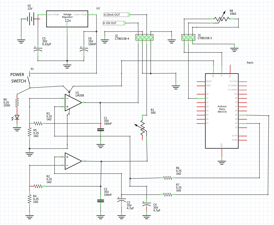
The heart of the design is the LM358 Dual Operational Amplifier (Op Amp). An Op Amp amplifies a signal and has a couple of main advantages over just using a BJT transistor as an amplifier because it has a very high input impedance (resistance) and a very low output impedance. It also has a very high gain but I'm not really using this function. I am using the Op Amp as a non-inverting amplifier with a gain of two which I will explain in an bit.
The signal fed to the amplifier is produced by the Arduino Nano. This comes in the form of a PWM signal (Pulse Width Modulation). Pulse width modulation works by producing a square wave at a set frequency. By changing the pulse width, devices can simulate varying levels of voltage, on the Arduino the wider the width of the pulse the closer to 5V and the narrower the pulse the closer to 0V. The width of the pulse is controlled manually by turning a 10K potentiometer that is connected to an analog input (A1) on the Arduino Nano. I can't use this signal in Industrial Controls because the I need a DC 0-10V signal or a DC 4-20mA signal. The first thing I do to the signal is smooth it out with a resistor and capacitor in a low pass filter arrangement. This arrangement smooths out the PWM signal and gives a 0-5V DC signal to the OP Amp circuit.
I am providing the Op Amp with two 0-5V signals generated by the Arduino PWM signal. One for the 0-10V output signal and one for the 4020mA Signal.
Getting a 0-10V Signal from the Op Amp in Non-Inverting mode is easy as I simply want to double the output of the signal. When the voltage at the non-inverting amplifier input (+) is higher than the inverting input (-), the output voltage swings towards the positive supply voltage. Conversely, if the voltage at the inverting input is higher, the output swings towards the negative supply voltage. Some of the output signal is basically fed back to the amplifier to manage the gain. This feature allows the LM358 to handle signals near the supply voltage rails and does not need a negative supply. The gain of an Op Amp in non-inverting mode can be calculated with the equation Gv = R1+R2/R2. I am using 1k OHM resistors for both R1 and R2 therefore my gain is Gv = 1+1/1 = 2. I have a gain of 2 therefore my output is between 0 and 10V.
Getting the 0-20mA signal is only slightly more complicated. I still use exactly the same set up as the 0-10V signal and still get an output of 0-10V however I then output this signal through a 500 Ohm trim potentiometer. I also modify the code on the Arduino so the PWM signal doesn't give an input voltage down to 0V I only want it going down to 1V, 2V after it's gone through the amplifier. Using Ohms law it it very simply to work out the current going through this circuit. Current (I) = Voltage (V) / Resistance (R). Therefore at 2V and 500 Ohms, I = 2/500 = 0.004A (4mA) and at 10V, I = 10/500 = 0.02A (20mA). Normally you would use 24V to drive a 4-20mA signal however using 10V is no big deal because the whole point of using a current loop instead of a voltage loop is to make the signal resistant to changes in voltage. The trim potentiometer is used instead of a fixed resistor so the output can be tuned to account for any additional resistance in the circuit.
Below is a schematic of the circuit.
![]()
The YouTube Video below shows on the oscilloscope how the signal changes from a PWM signal to smoothed out to 0-5VDC to the amplified to 0-10VDC.
-
2Assembly
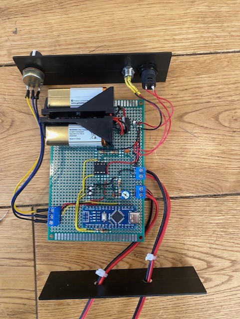
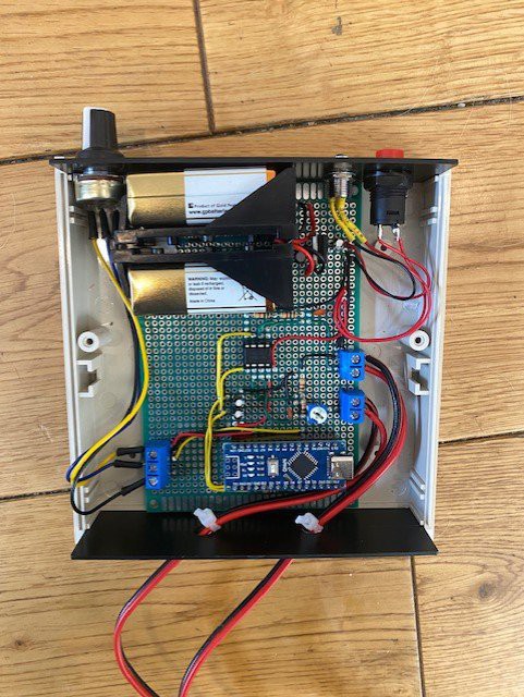
As I mentioned in the beginning I really very much needed this signal generator as a tool to test a control circuit over a weekend and I couldn't find my commercial loop calibrator anywhere. This is why it was assembled on prototyping board using 26AWG solid hook-up wire. I find 26AWG wire works best for me in this scenario but others might prefer thicker or thinner hook wire.
I tend to solder the lower components first then work up to the taller components. A tip I find helps is to use a bit of blue tack to hold the components in place while soldering.
Another tip is that I use a couple of cable ties (zip ties) as strain relief on the output cables to stop any force pulling the wires from the screw terminals.
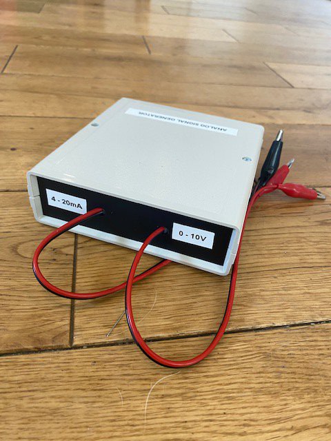
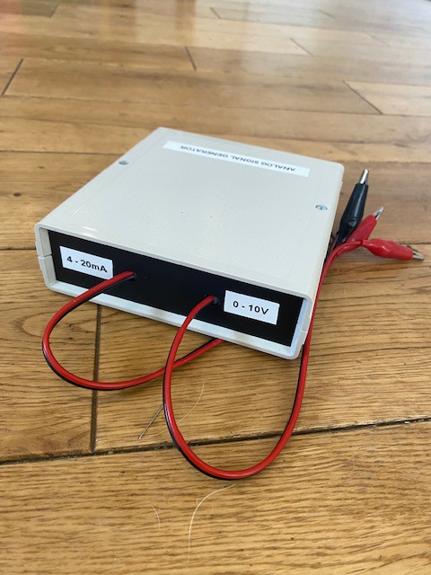
Below are some pictures of the assembly.
![]()
![]()
![]()
![]()
-
3Software
To be honest you really don't need a microcontroller for this project and you could easily use a couple of 555 Timers or 556 Timers to generate the PWM. It might actually work better because the PWM can then be at a higher frequency giving a smoother DC output when using the low pass filter.
I had a Arduino Nano in my parts bin so I just used it with a little bit of code to generate the PWM signal.
The code is below and in the files section.
/* For Full project description go to https://hackaday.io/project/193211-diy-industrial-controls-analog-signal-generator */ const int analogInPin = A1; // Analog input pin that the potentiometer is attached to const int analogOutPin = 3; // Analog output pin that the LED is attached to const int mAOutPin = 5; // Analog output pin that the LED is attached to int sensorValue = 0; // value read from the pot int outputValue = 0; // value output to the PWM (analog out) int mAOut = 0; void setup() { // initialize serial communications at 9600 bps: Serial.begin(9600); } void loop() { // read the analog in value: sensorValue = analogRead(analogInPin); // map it to the range of the analog out: outputValue = map(sensorValue, 0, 1023, 0, 255); mAOut = map(sensorValue, 0, 1023, 50, 255); // change the analog out value: analogWrite(analogOutPin, outputValue); analogWrite(mAOutPin, mAOut); // print the results to the Serial Monitor: Serial.print("sensor = "); Serial.print(sensorValue); Serial.print("\t output = "); Serial.println(mAOut); // wait 2 milliseconds before the next loop for the analog-to-digital // converter to settle after the last reading: delay(2); } -
4Testing
I tested the signal generator by connecting it to the inputs of a Siemens Logo PLC. I use these PLC's on my Industrial Controls Projects so I am pretty familiar with writing PLC software for them. I always write my PLC software in ladder logic but the LOGO! SoftComfort PC software allows you write sofware in Ladder Logic (LAD), Function Block Diagrams (FBD) and User Defined Function Block (UDF).
To test the function of the signal generator I use a Analog Threshold Trigger in the Software. This monitors the analog input on the PLC and then makes a something happen depending on what you have set the Threshold value to. You can set the Threshold Trigger to work with several different analog input protocols but I will use just 0-10V and 4-20mA. You set when the output turns "on" and "off" by setting the threshold to values between 0 and 1000. 0 represents 0V or 4mA and 1000 represents 10V or 20mA.
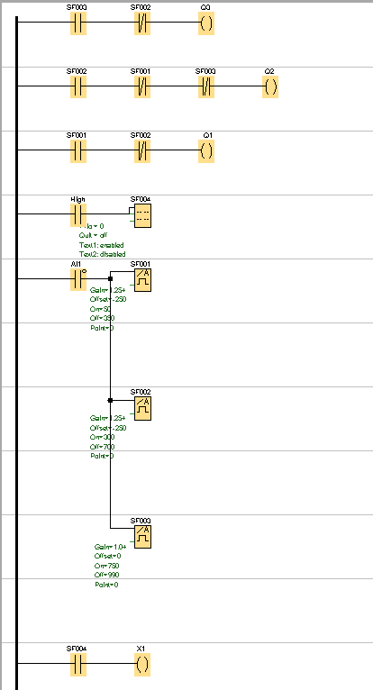
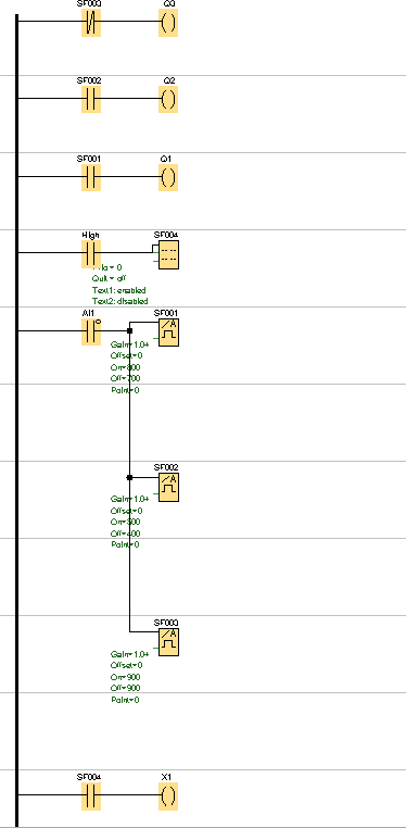
I wrote two very simple PLC programs, both of which change the condition of the PLC Outputs 1, 2, and 3. I used a PLC with relay outputs as I tend to use these in Industrial Controls however the Siemens Logo can also have transistorised outputs. The PLC's with transistorised outputs have some advantages as they can then be used to output and analog signal and even a PWM signal.
PLC program using 4-20mA.
![]()
PLC program using 0-10V.
![]()
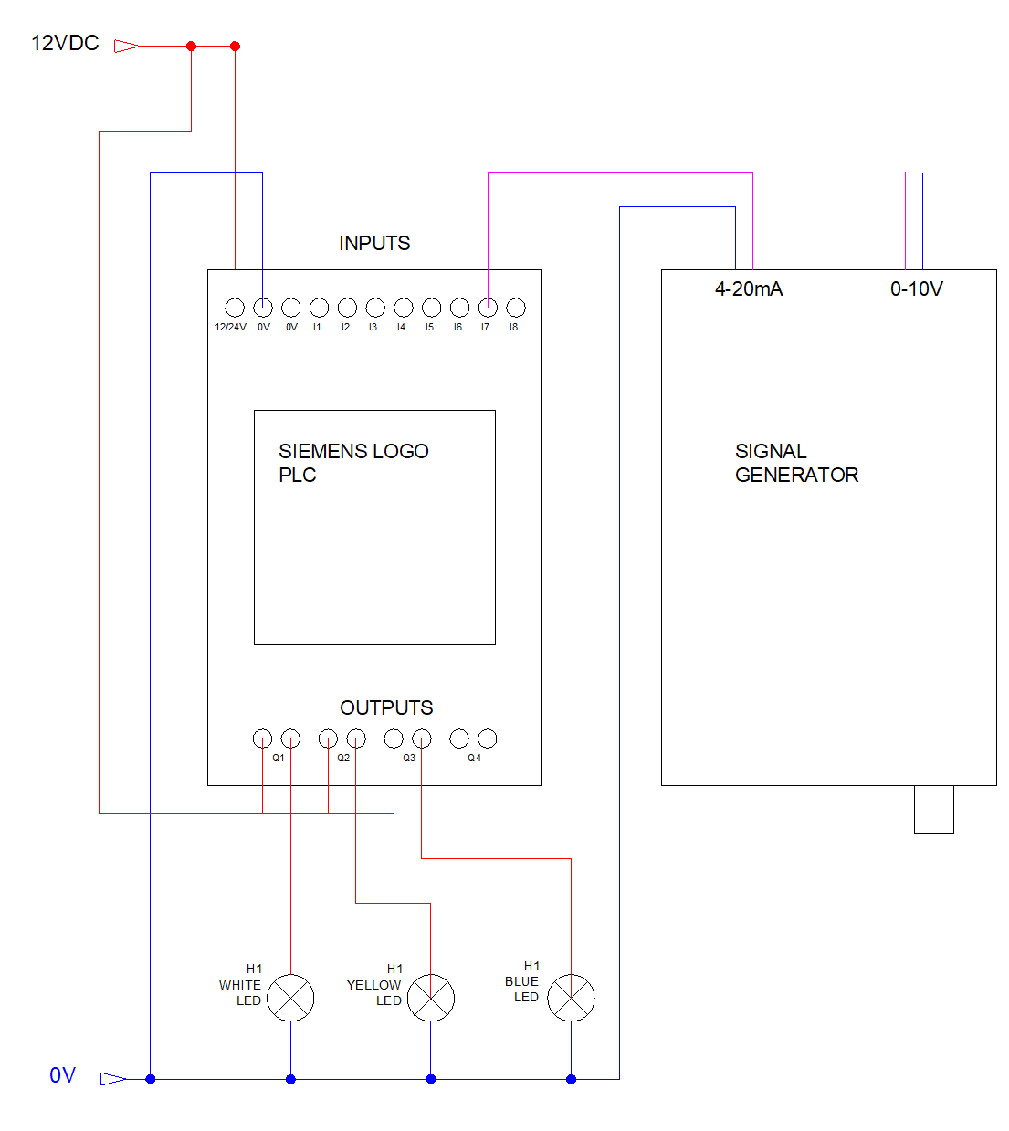
Below is schematic showing my hardware setup for testing.
![]()
The YouTube video below shows the setup being tested.
Analog Signal Generator for Industrial Controls
Sensors and Instruments in Industrial Controls often use 4-20mA or 0-10V analog signals I needed a replacement signal generator in a hurry!
 Tom Goff
Discussions
Become a Hackaday.io Member
Create an account to leave a comment. Already have an account? Log In.