Finally I 3D printed a mount for a slim DVD drive, mounted a USB/SD Card front pannel on the alu profiles and a 3D printed fixture and mounted the front plane on some wood spacers and applied an old Apple sticker :-)
The final benchmark results are really nice and the only noiseI I spotted was from my (old) monitor when I did not turn off the sound card :-) Initial test over 19.000 points in Cinebench R23 and also the stability test is only minor points below 19.000.
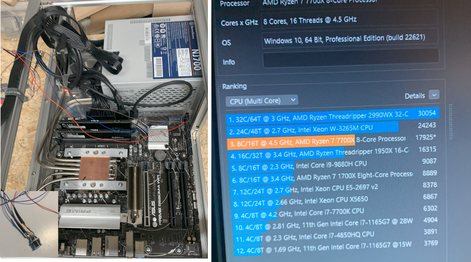
After soldering the power connector I had everything to start the first tests .... also the benchmarks had not been too bad the CPU got very hot and the system was not really stable....
I glued temperature sensors to several positions of the alu cooler and the copper blocks and used an Arduino Nano to measure the temperature at different positions. I had teh feeling that some of teh pipes did not work correctly and asked for help in the internet. After some de-mounting and remounting, bending of 3 new heat pipes and finding that the orientation of the PC was quite important for the performance, I finally solved my challenges. Please see here for more information on the debugging:
In contrast to a normal cooler with only one surface between CPu and cooler, I had to mount several pieces at teh same time. It was a bit of a challenge! I tried to first mount the ends at the cooler, then put the pipes in the copper block at the CPU and then closing this copper block. As can be seen in the lower right picture, the thermal pasted was quite well spread over the copper block (I had to dismount, but read more later .....). Also the alu sheets (I think it was 2mm or more) bended quite a bit when i tried to apply pressure to the blocks.
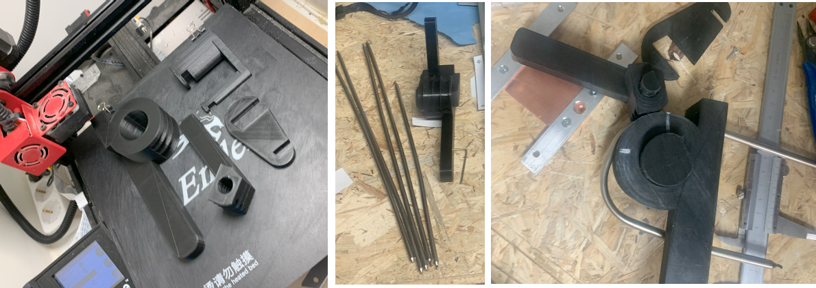
First I 3D printed a heatr pipe bender. This worked well but maybe I was not carefull enough in the beginning when bending, you will read later whey ...
Step by step I adjusted all five heatpipes not to touch anything and form a good connection from the CPU towards the cooler: To fix the copper blocks I also used a small piece of alu with holes and drilled screw holes inside the alo cooler.
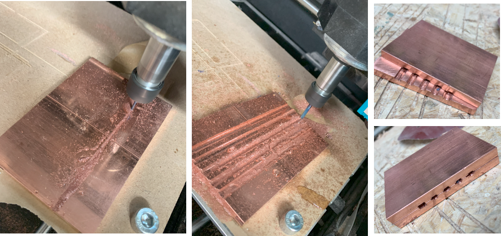
To guide the drilling and get exact dimenions I pre-milled the copper blocks a bit less than the final holes. Putting each copper block next to the other ensured that they will later fit to each other when flipped.
Putting the two blocks together and mounting within a wise, I was able to drill the holes in the exact diameter I needed. After the first hole was drilled, a drill bit was used to avoid that both copper blocks moved while drilling. Cleaning the holes, tapping screw holes to press both blocks together was the next step for the CPU copper block adapter. Finally I used a bit of scrap aluminium to make a fixture of teh copper block which I could then screw into the holes of the mainboard for the cooler. The smaller copper blocks to mount the heat pipes to the alu ribbon cooler I drilled directly which also lead to the loss of one of the drill bits :-)
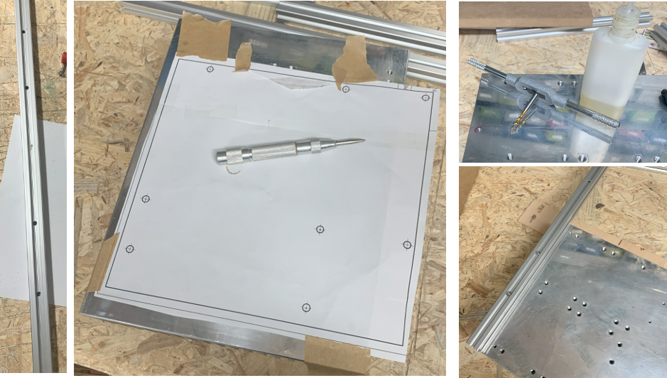
I printed the layout of the mainboard holes, punshed, drilled and and tapped holes to mount teh mainboard as well as the alu frame.
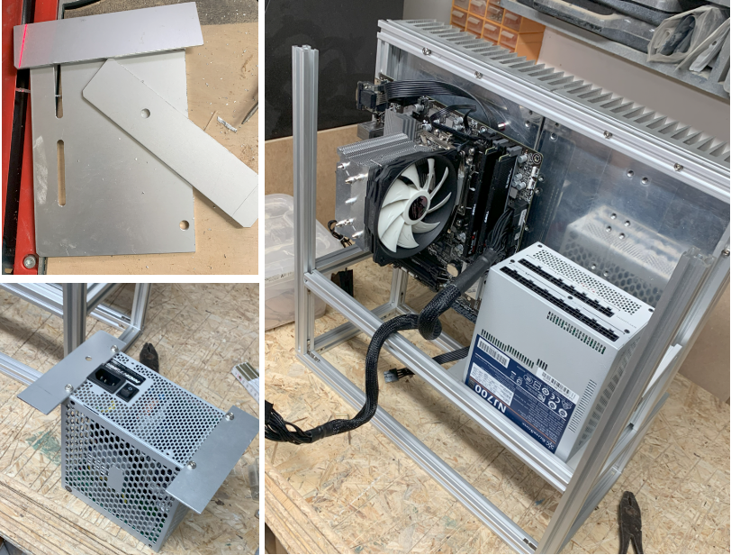
With some distance bolts I mounted the PCB to the alu cooler (in fact only to one of both, not to induce mechanical stress to the board when the coolers would relative move. To mount the power supply, I used some spare aluminium sheets, drilled holes and fixated the sheets inside the alu profiles
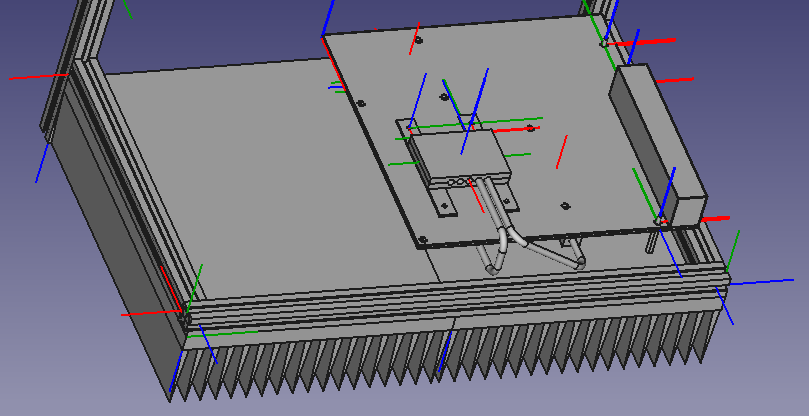
Before I ordered the parts and started the build, I draw a rough 3D scetch of the build to get an idea of the dimensions.
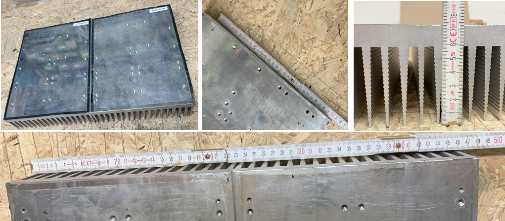
After the cooler and the aluminium profiles (20x20) arrived, the build started:
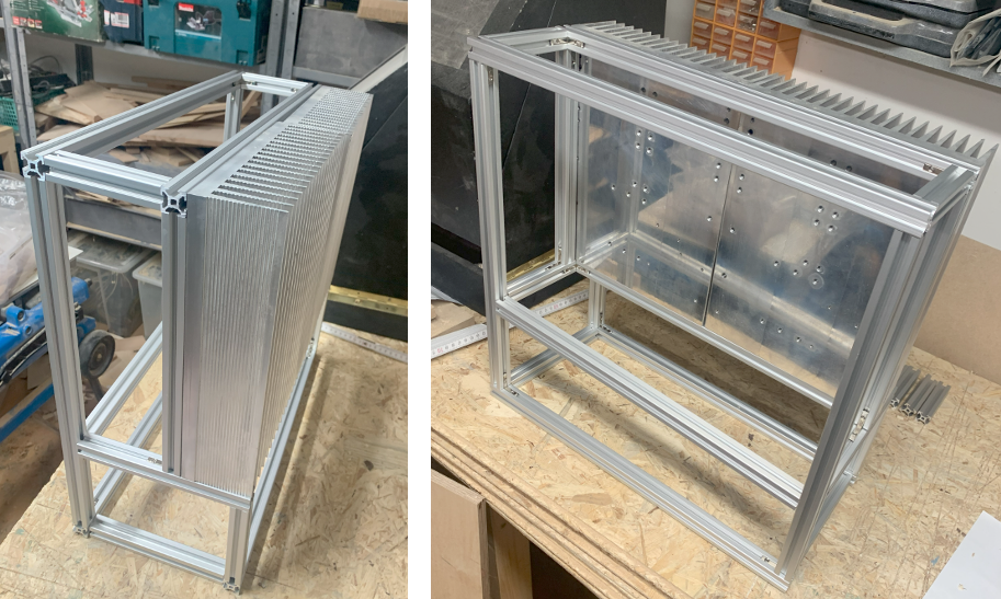
Building the frame from teh profiles (Note; the initial plan was to have the PC standing like this but finally I removed the lower part and put the PC flat on teh floor, see late rblog posts):
By using our website and services, you expressly agree to the placement of our performance, functionality, and advertising cookies.
Learn More
 BastelBaus
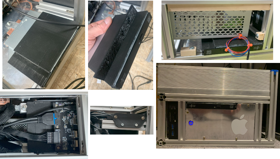 The final benchmark results are really nice and the only noiseI I spotted was from my (old) monitor when I did not turn off the sound card :-) Initial test over 19.000 points in Cinebench R23 and also the stability test is only minor points below 19.000.
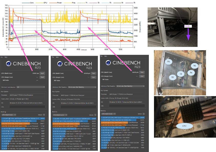
 I glued temperature sensors to several positions of the alu cooler and the copper blocks and used an Arduino Nano to measure the temperature at different positions.
 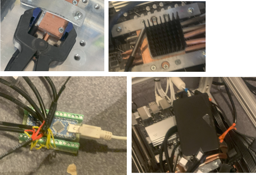 I had teh feeling that some of teh pipes did not work correctly and asked for help in the internet. After some de-mounting and remounting, bending of 3 new heat pipes and finding that the orientation of the PC was quite important for the performance, I finally solved my challenges. Please see here for more information on the debugging:
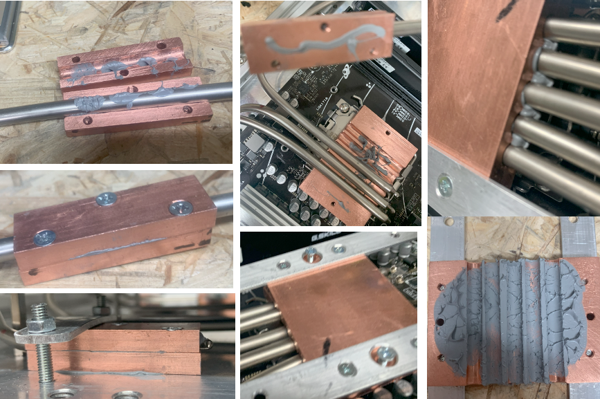
 Step by step I adjusted all five heatpipes not to touch anything and form a good connection from the CPU towards the cooler:
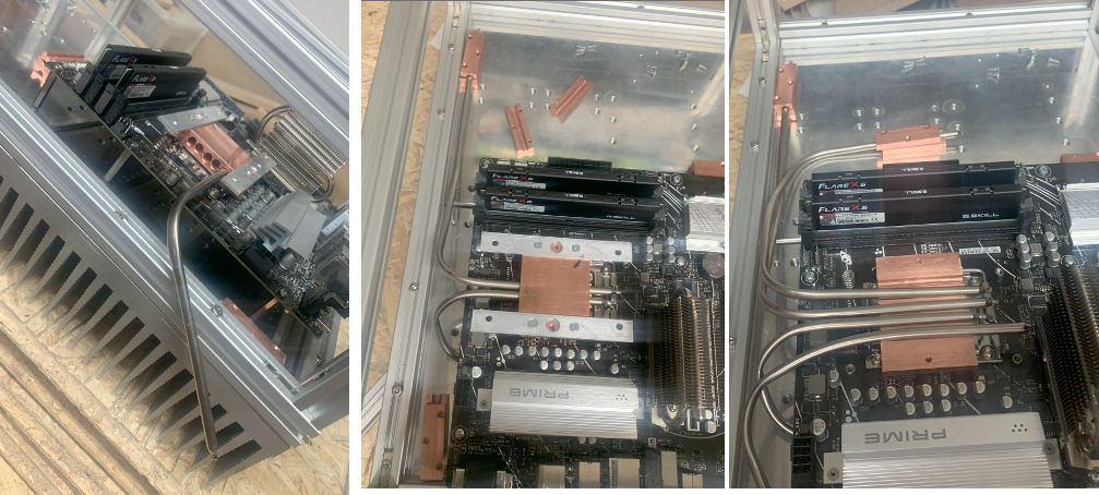 To fix the copper blocks I also used a small piece of alu with holes and drilled screw holes inside the alo cooler.
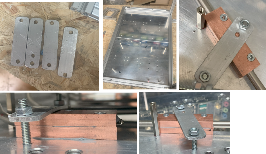
 Putting the two blocks together and mounting within a wise, I was able to drill the holes in the exact diameter I needed. After the first hole was drilled, a drill bit was used to avoid that both copper blocks moved while drilling.
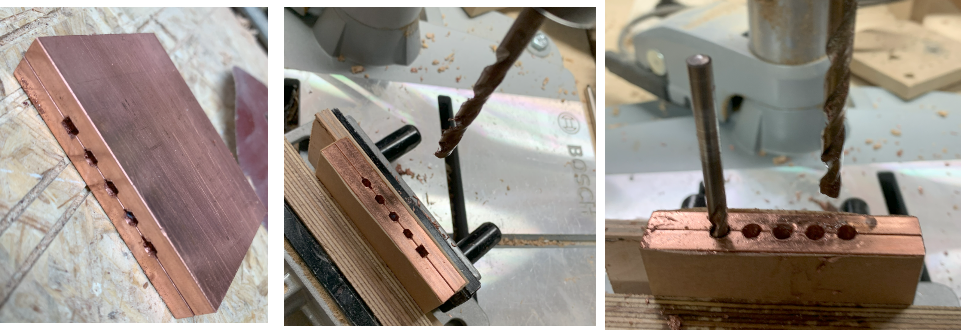 Cleaning the holes, tapping screw holes to press both blocks together was the next step for the CPU copper block adapter.
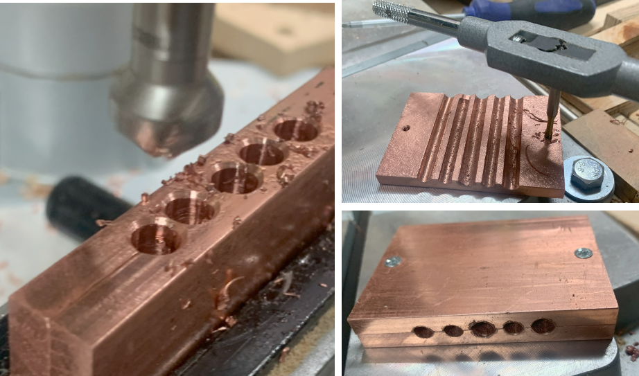 Finally I used a bit of scrap aluminium to make a fixture of teh copper block which I could then screw into the holes of the mainboard for the cooler.
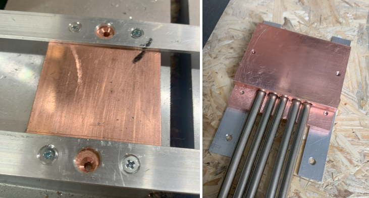 The smaller copper blocks to mount the heat pipes to the alu ribbon cooler I drilled directly which also lead to the loss of one of the drill bits :-)
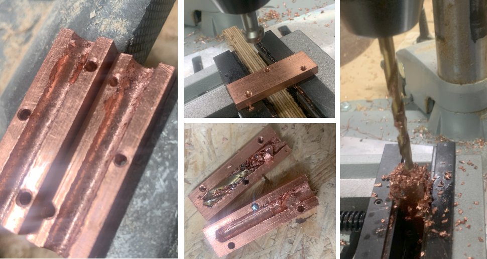
 With some distance bolts I mounted the PCB to the alu cooler (in fact only to one of both, not to induce mechanical stress to the board when the coolers would relative move.
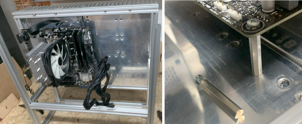 To mount the power supply, I used some spare aluminium sheets, drilled holes and fixated the sheets inside the alu profiles