0%
0%
An Old Fashion Acoustic Modem for the iPhone
My son recently returned from a holiday in China. His biggest complaint was the blocking of FaceBook!
 agp.cooper
Become a Hackaday.io member
Already have an account? Log in.
Just one more thing
To make the experience fit your profile, pick a username and tell us what interests you.
Pick an awesome username
hackaday.io/
Your profile's URL: hackaday.io/username. Max 25 alphanumeric characters.
Pick a few interests
Projects that share your interests
People that share your interests
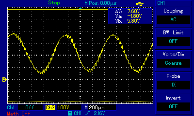

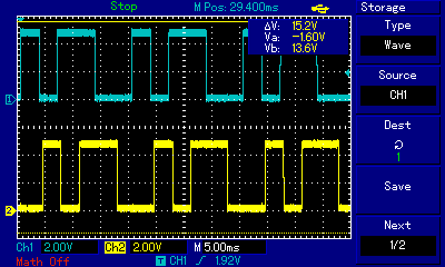
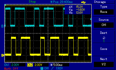
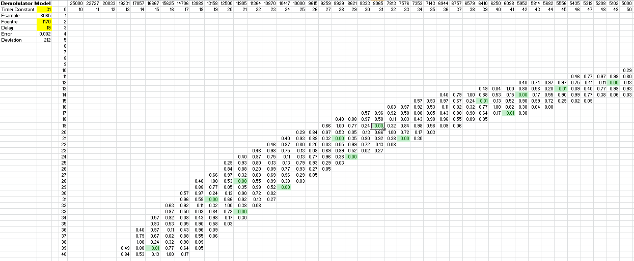
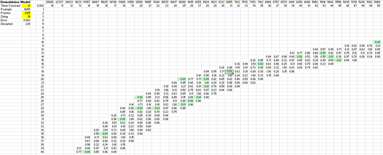
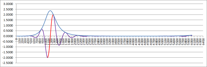
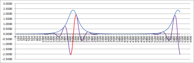

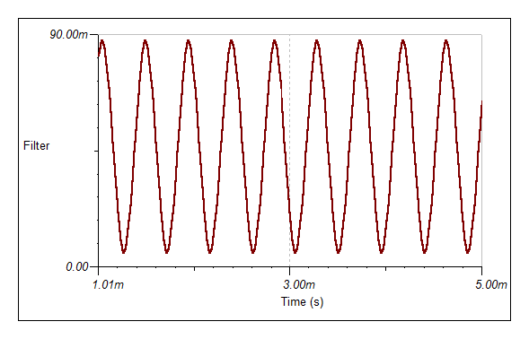
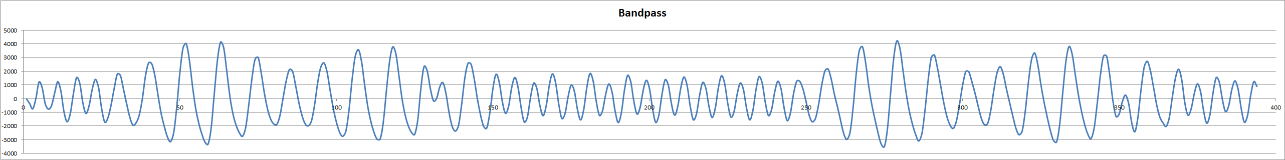
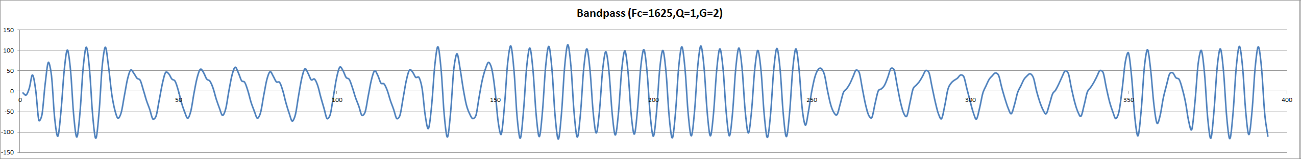
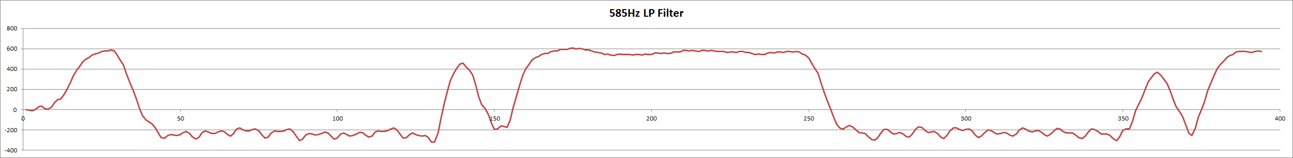
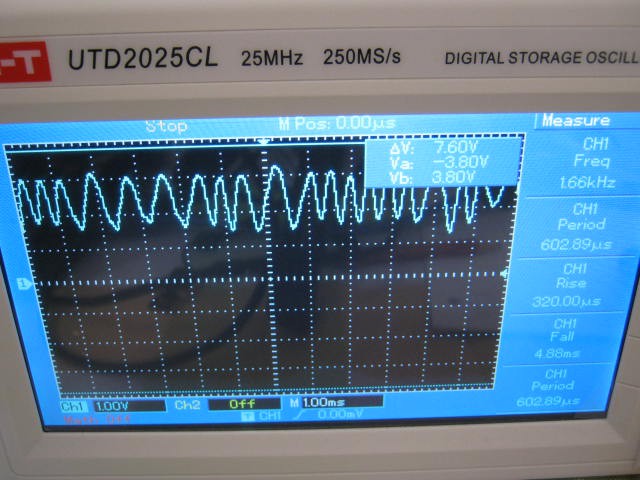
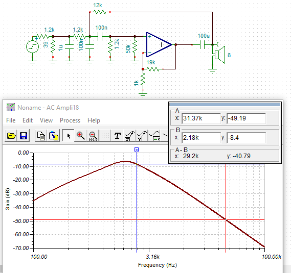
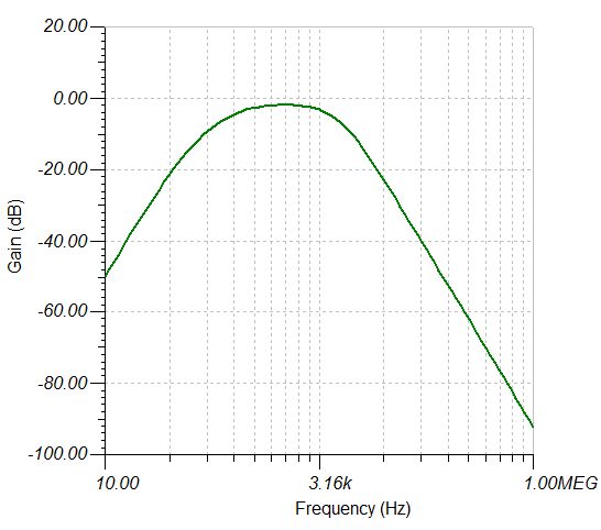
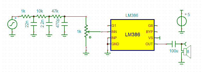
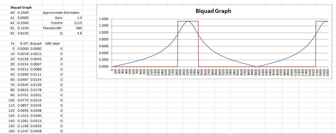 You may be able to see that the filter Q is closer to 3.6 than the design of 2.2.
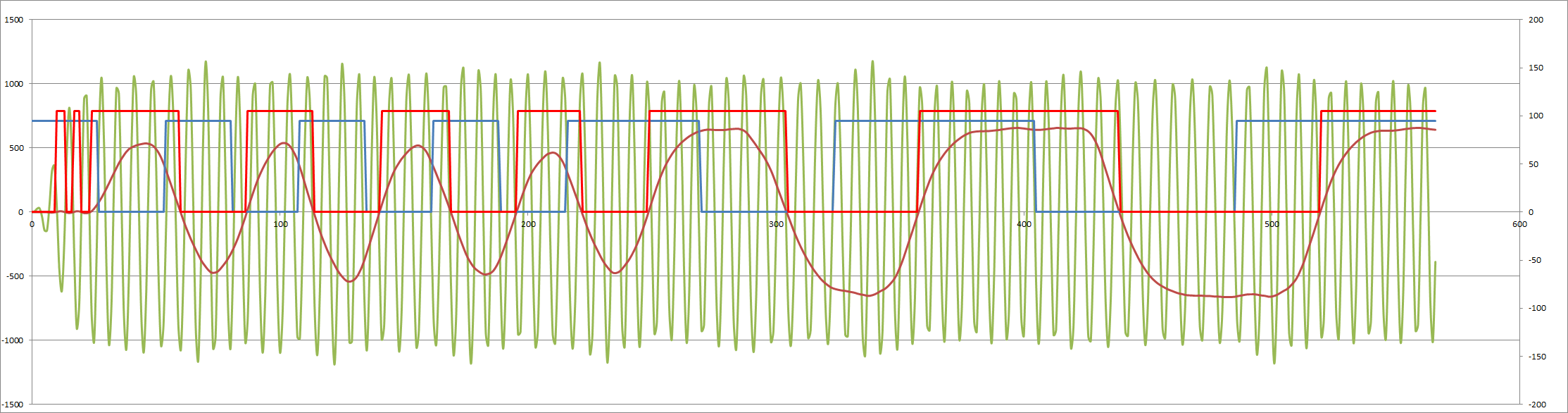
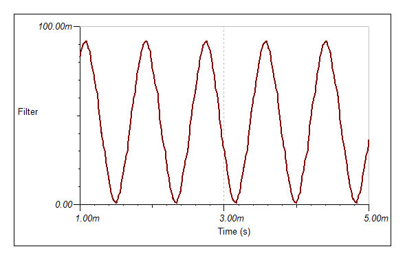
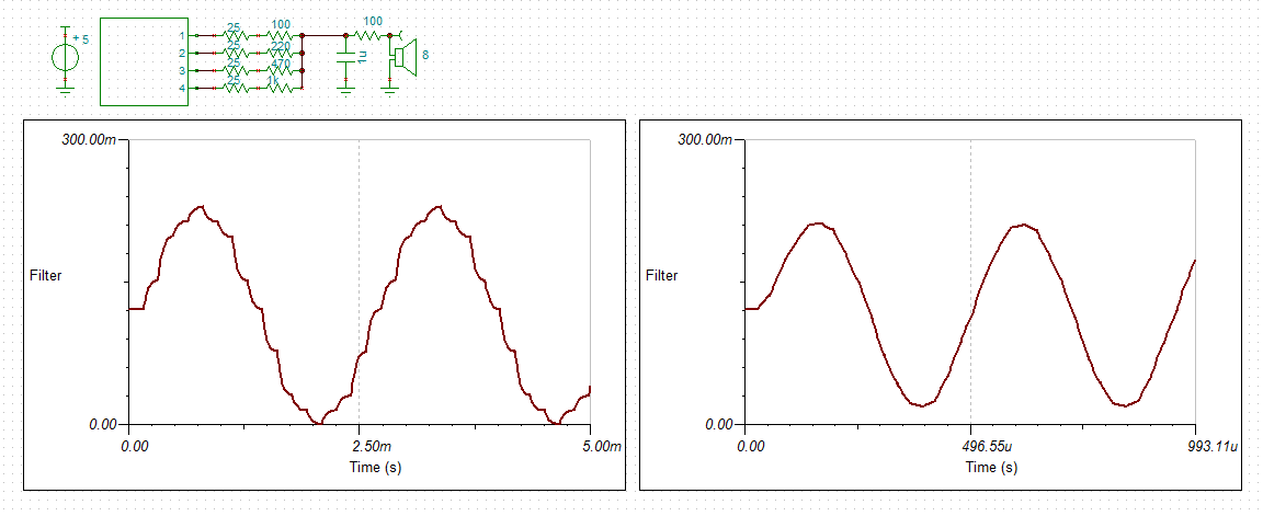


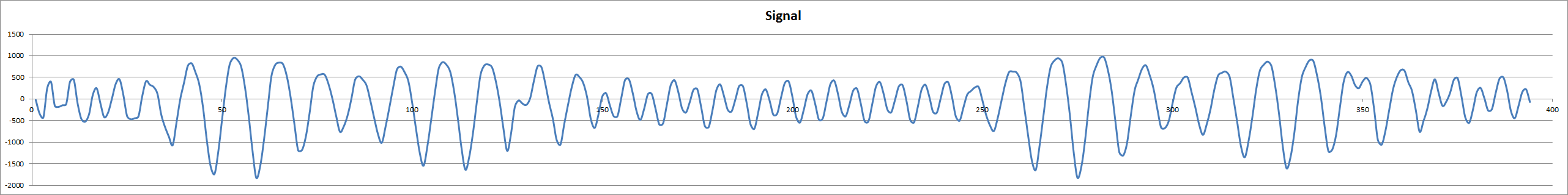
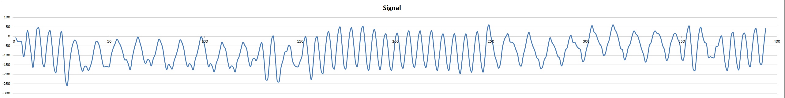
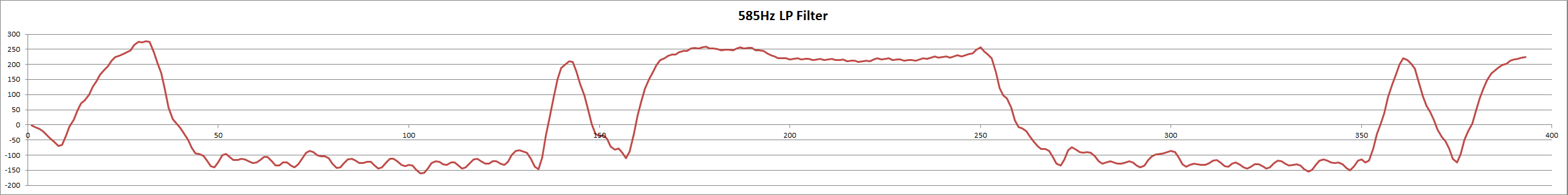


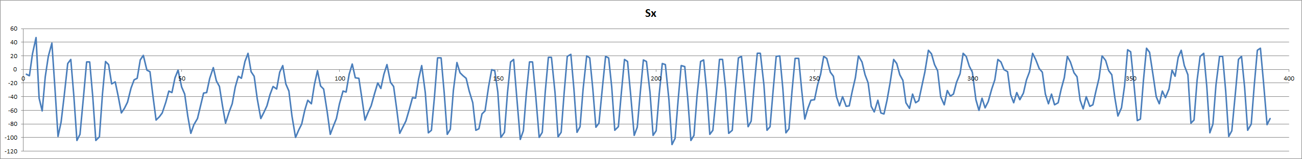
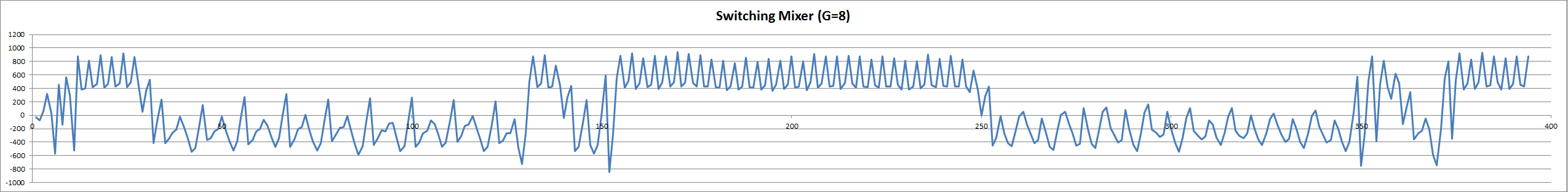
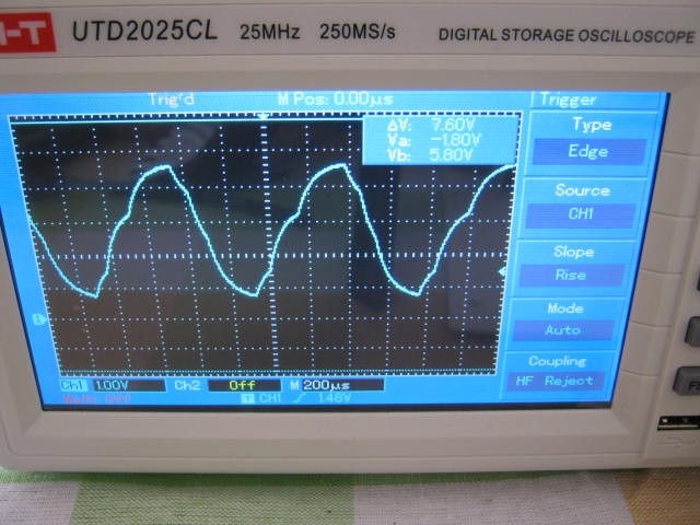


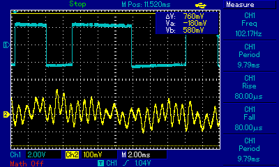
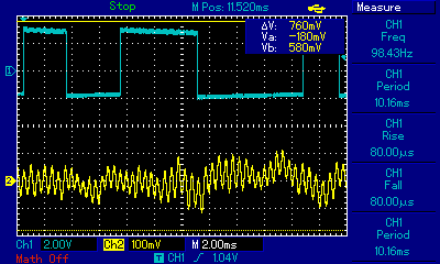
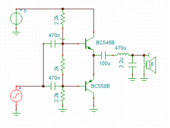
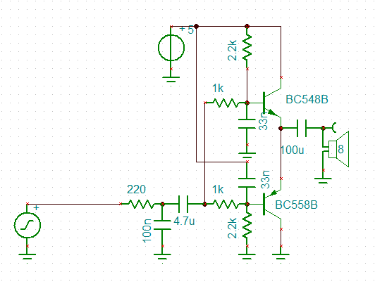
 Note that the top of the signal has less range than the bottom of the signal.
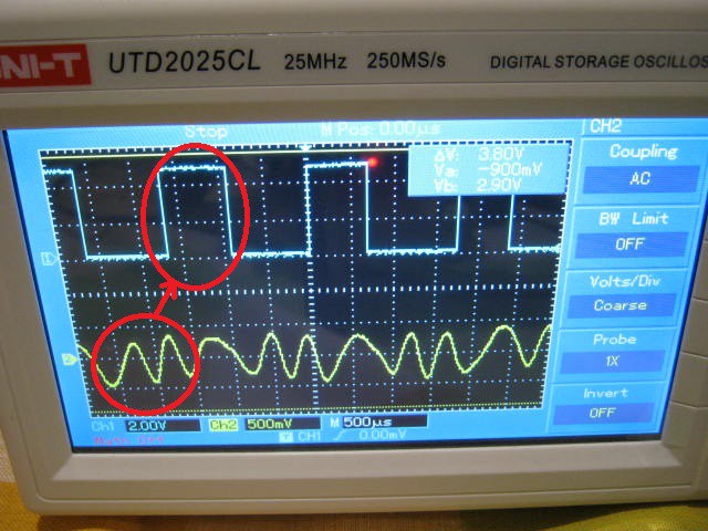


This is great stuff. Here are some links for you I've found doing my own research into creating a software modem:https://dotnewage.com/