I have started section #3, levels 120 through 180. The structure is printing up well, no need for modifications so far. As it turns out the levels 140, 160 and 180 all have the same floor beams and legs. I didn't plan it that way, its just the way it turned out. I have also designed Swing Arm #3 (easy) and I'm working on Swing Arm #4 (difficult).
A word of caution regarding the lights. I started out using as it turns out a very non-transparent gray filament. Everything was good until I needed more filament and the filament was no longer available. Without thinking I selected a new filament that was close to the same color and used that for the lights on Swing Arm #1. Only when the arm was completely constructed and attached did I realized the new filament was too transparent. This new filament has been OK for the various boxes and cabinets that sit on the floors, but not for the light shades. I eventually was able to get a new spool of the original filament and immediately printed up all the light shades I expect to need. So check the transparency of the grey filament before installing too many lights.
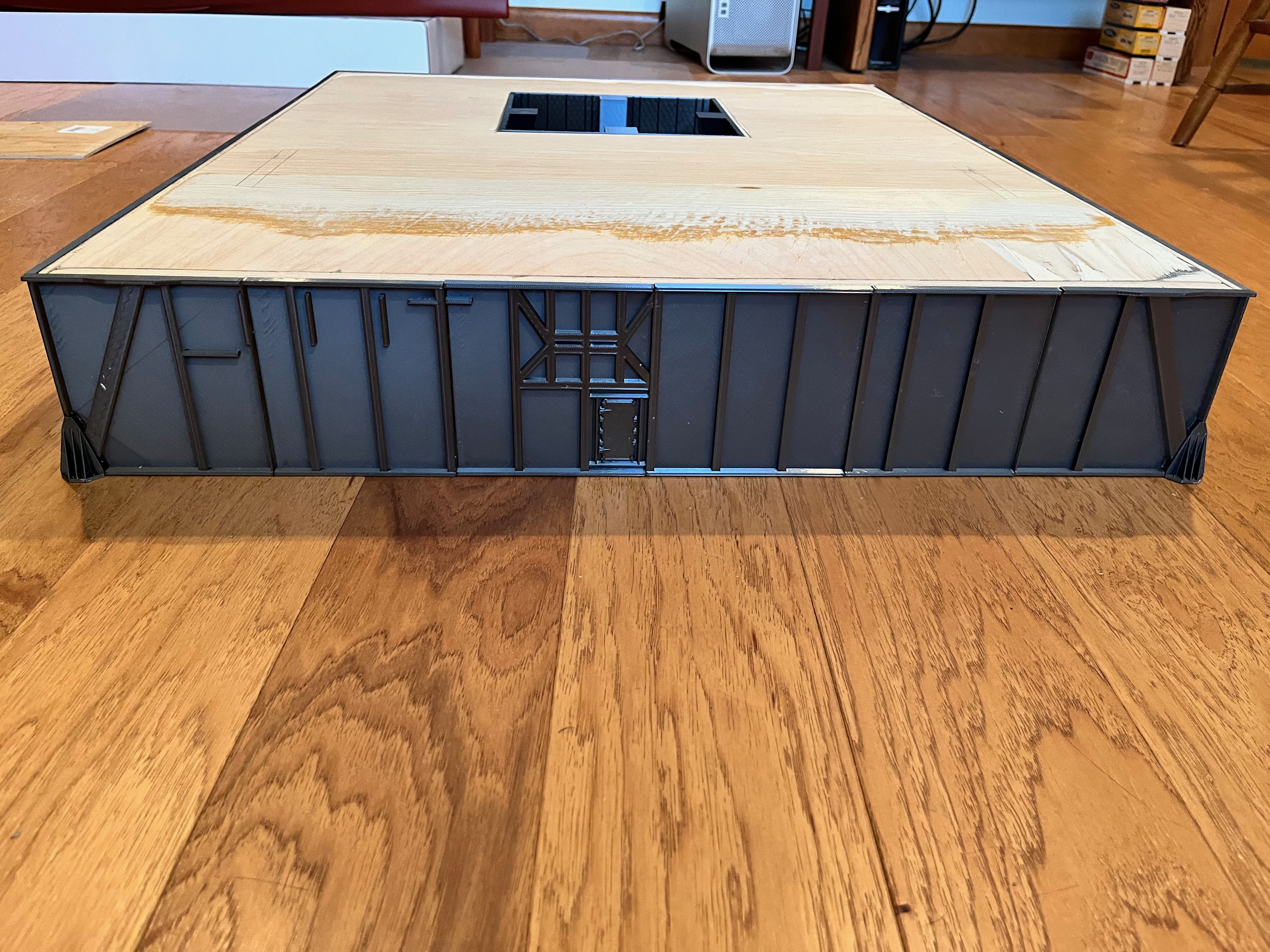
The structure and inner parts of level 120-140 is complete. This is the first floor of the next removable section #3.
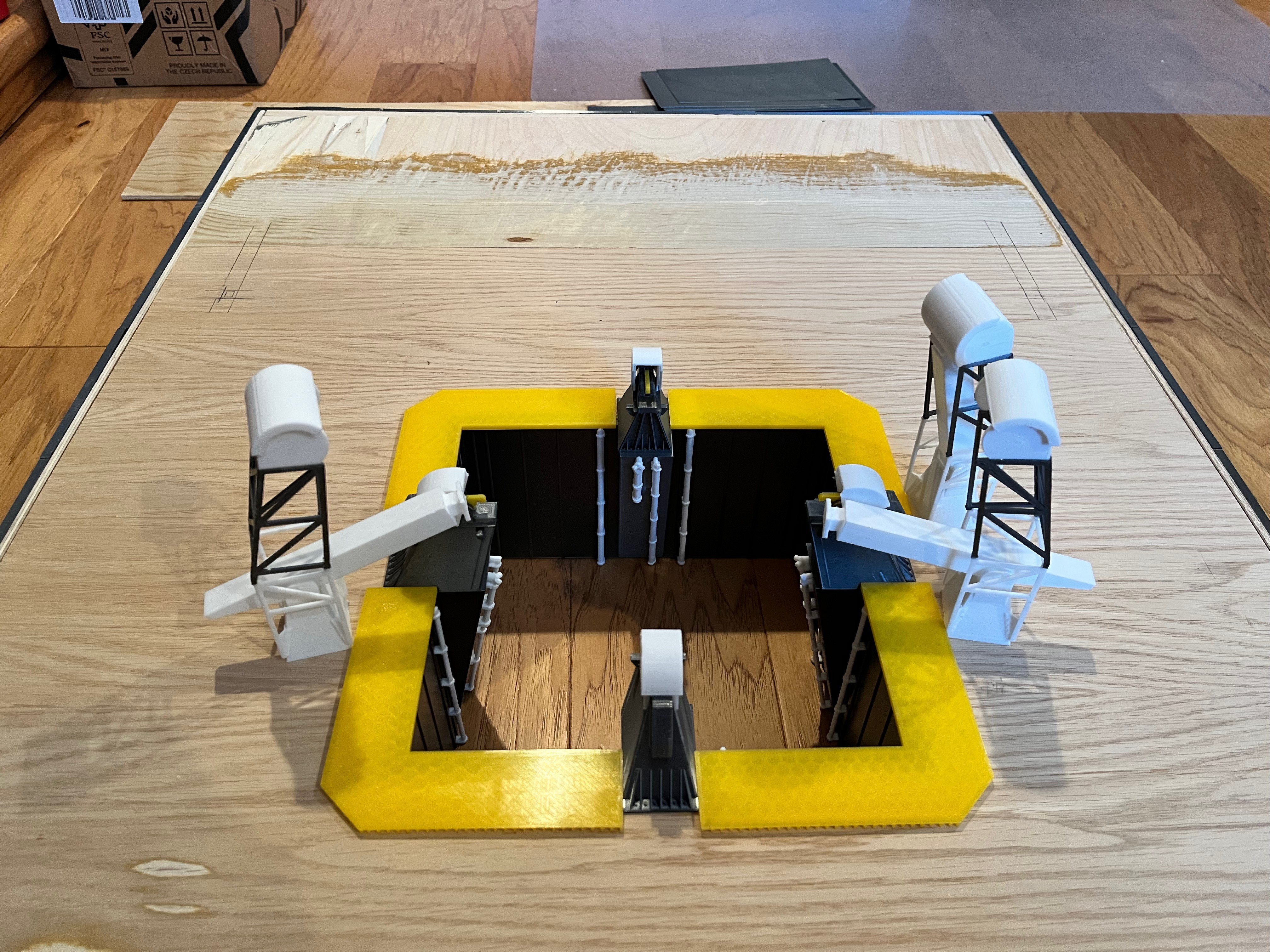
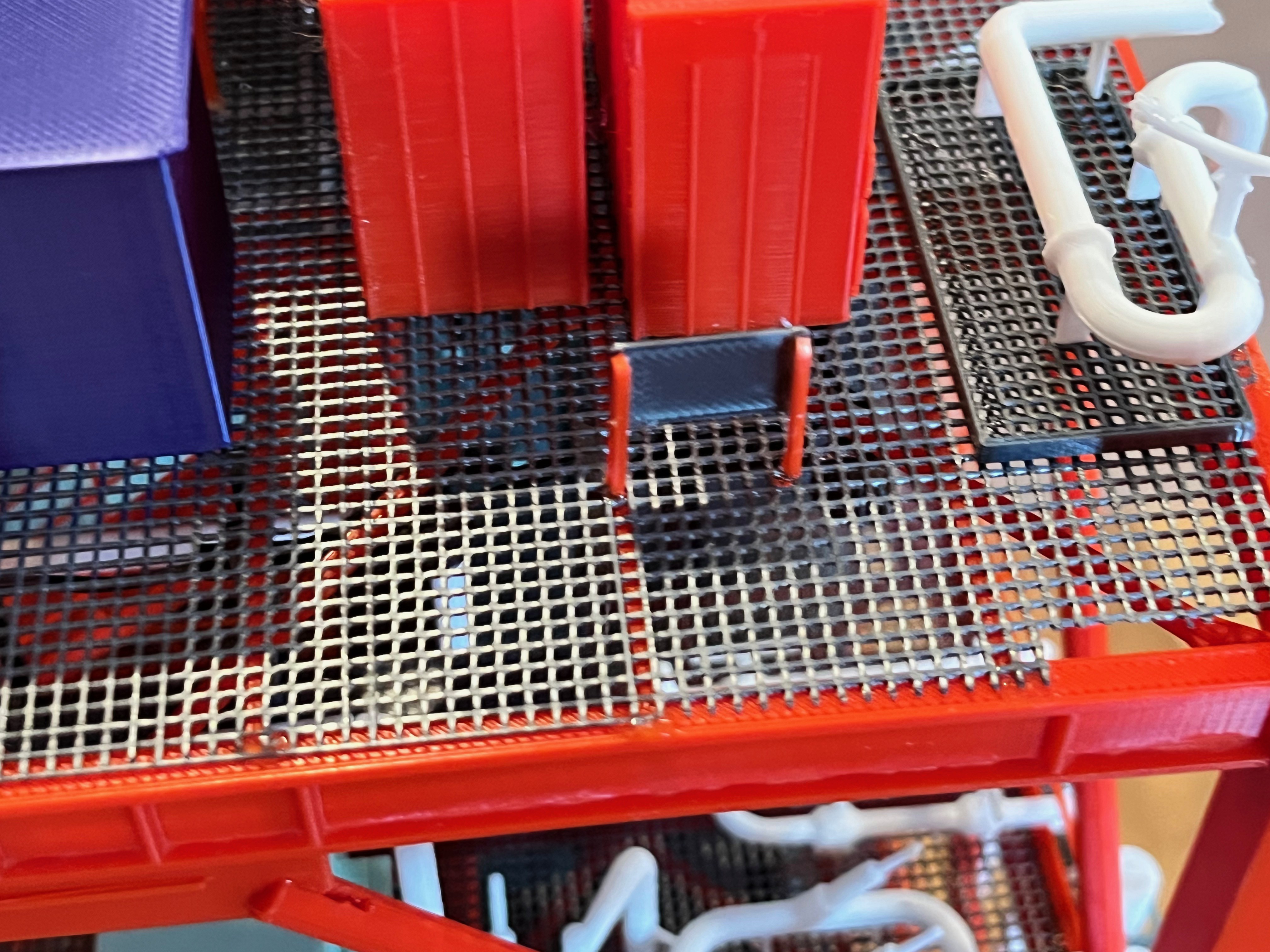
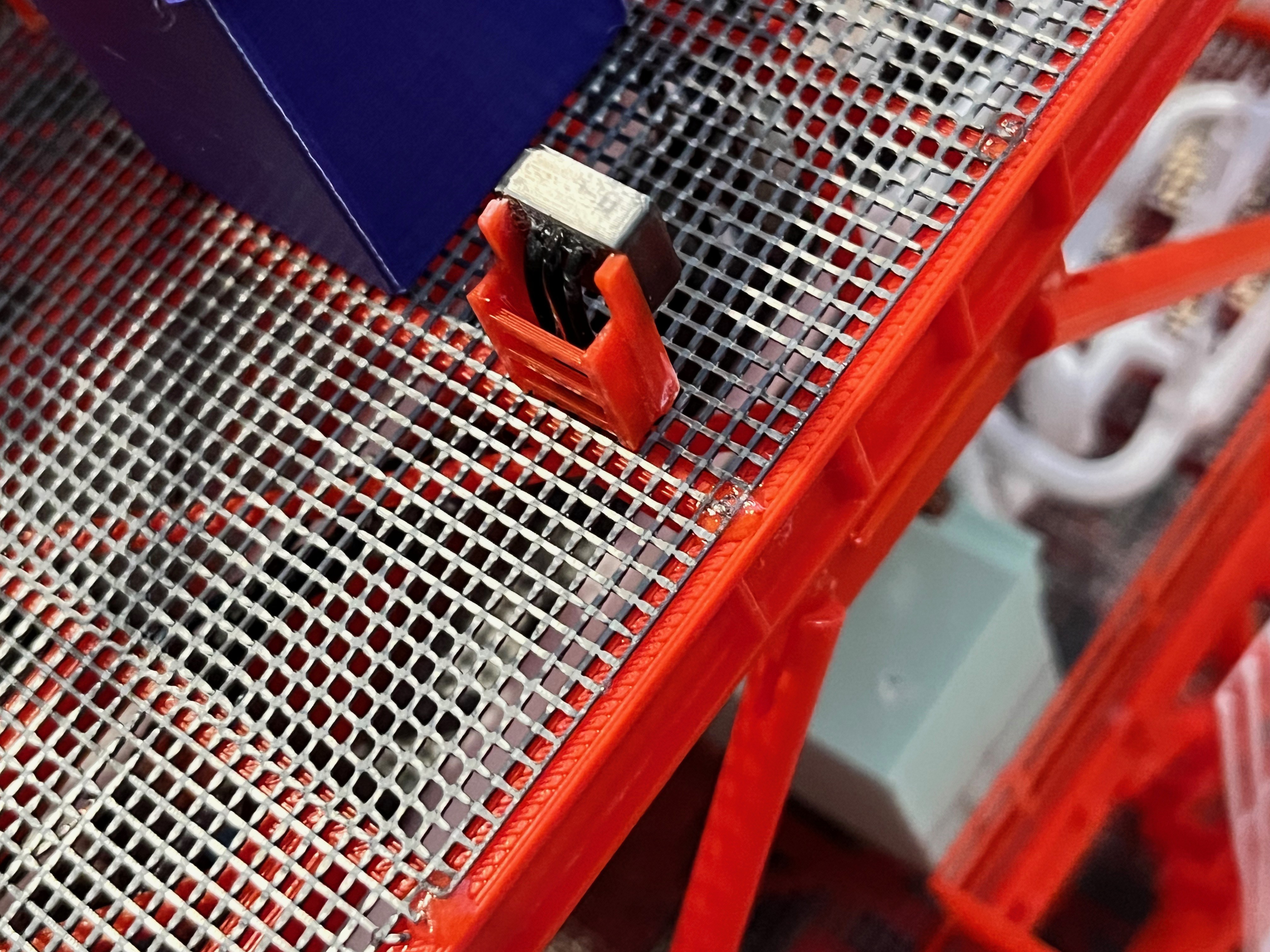
Thoughts on the Aviator67 parts. The part names align with the naming of parts in the MicroArtwork pdf files. Some of the names, usually storage boxes, for some reason do not have the same "Equ" number as in the MicroArtwork. I have not attempted to rename these. I have noticed that not all the parts have been modeled. There appears to be a size cut-off, too small and its not there. At the scale of this model, there are a few parts that I believe should be modeled. Many of these are small boxes that hang off the outside railing and are therefore fairly visible. Some of these boxes are about the same size so I created one box and will use that for many purposes. Specifically this part is named "L140 Crane Control Station". I first decided to model these at the next level. I may go back and add some of them to lower levels since the outside rails are easily accessible.
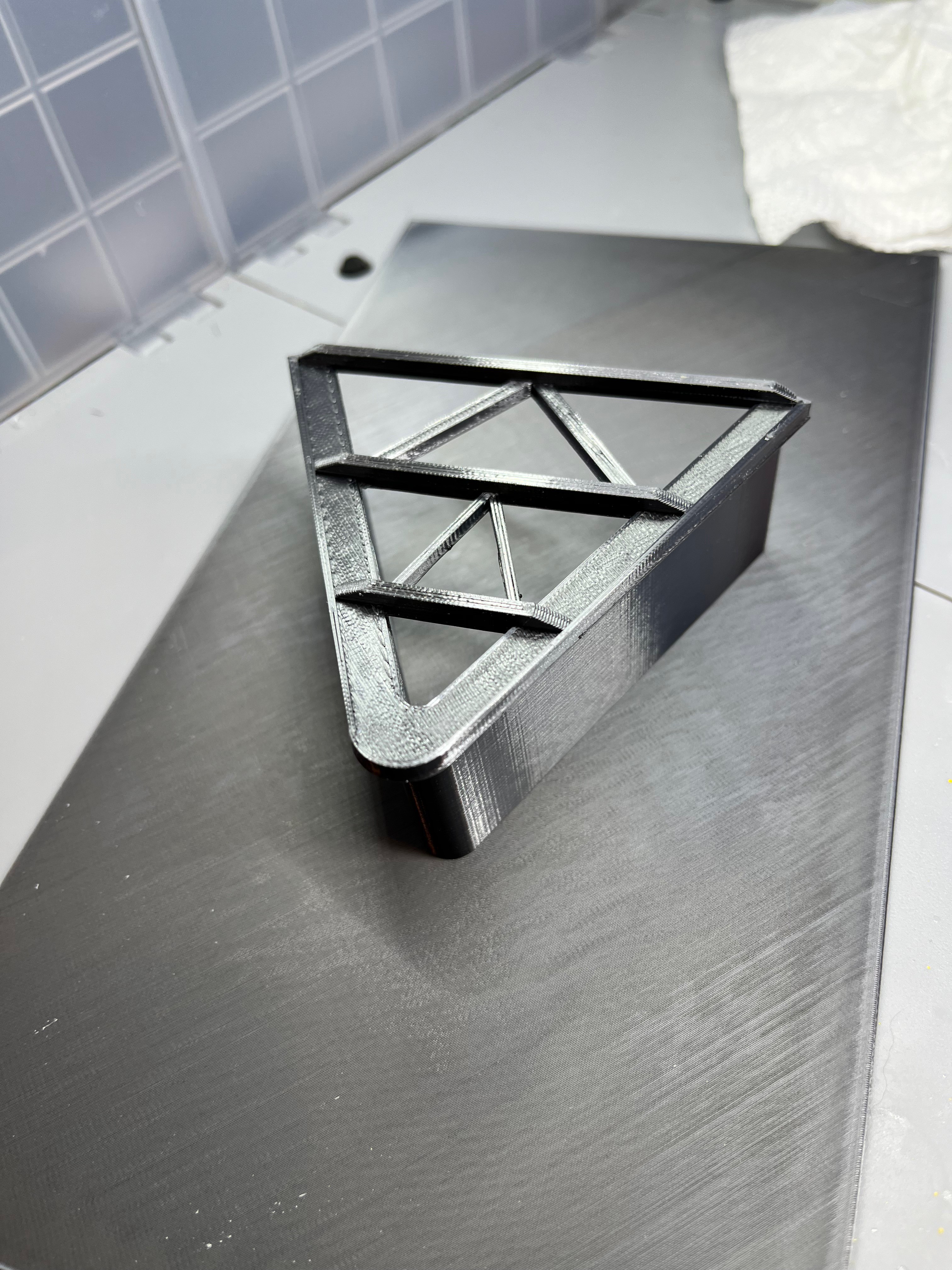
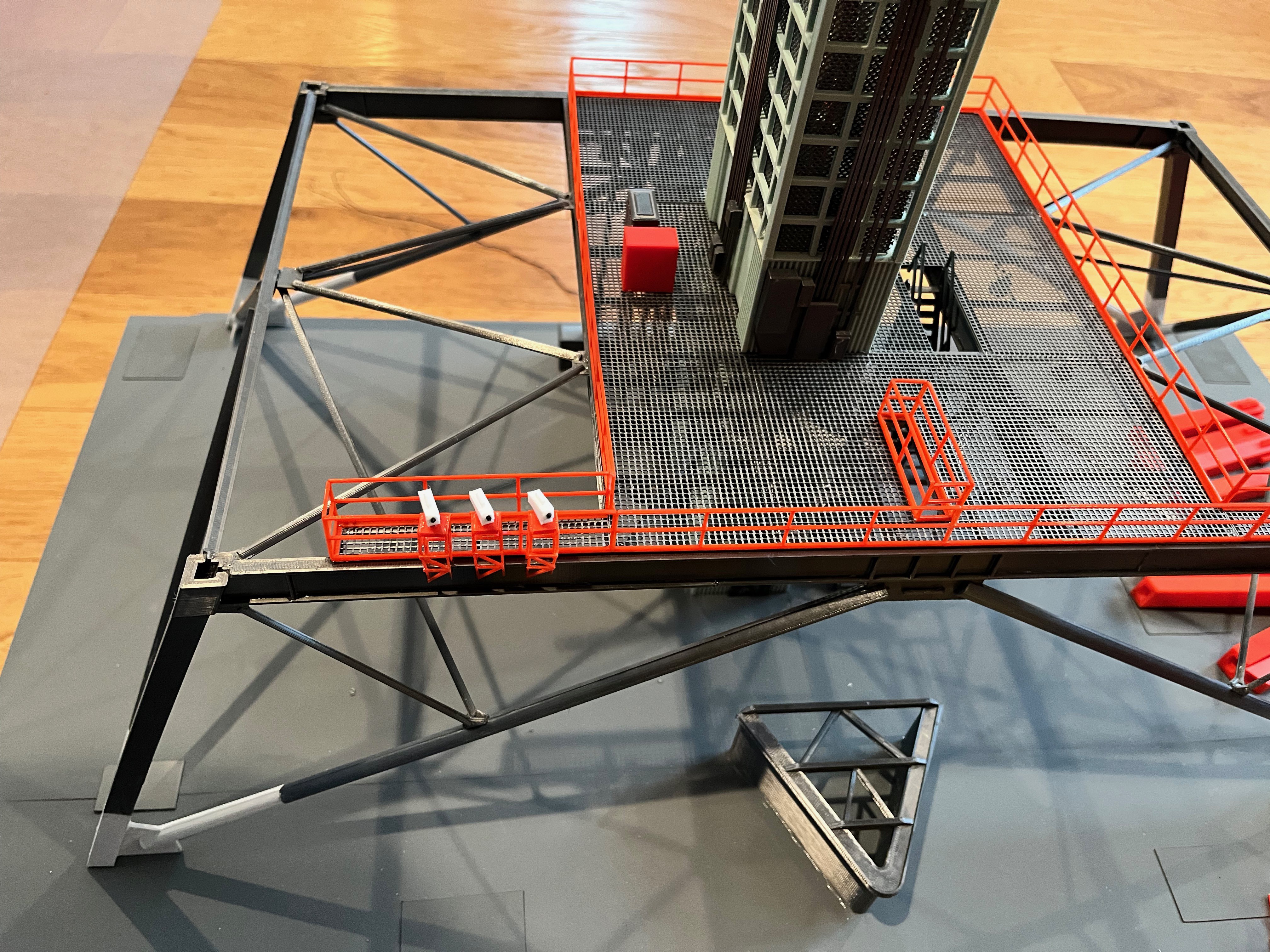
Level 120-140 camera platforms: There are two side ones and the standard corner one. They all have ladders to access.
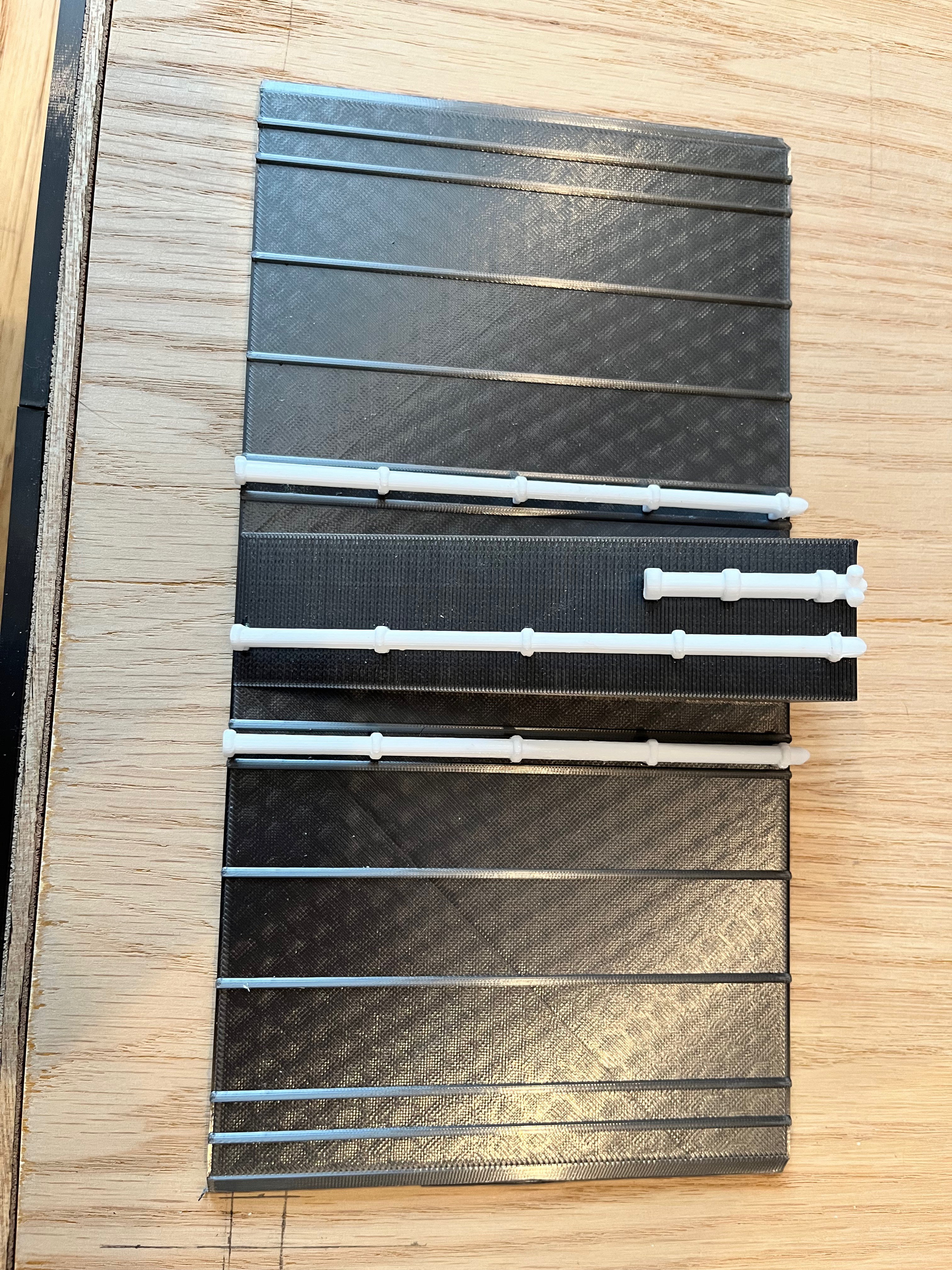
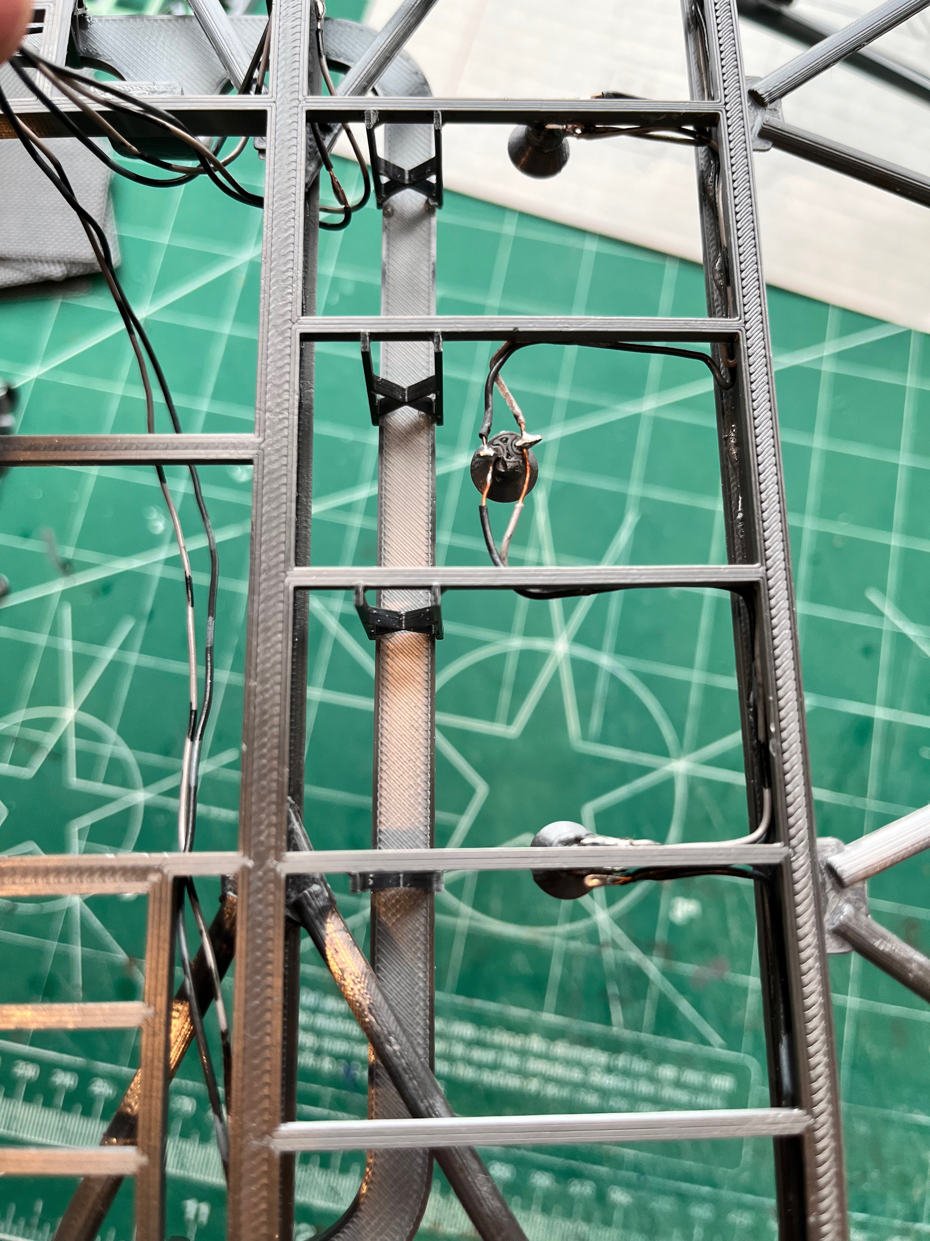
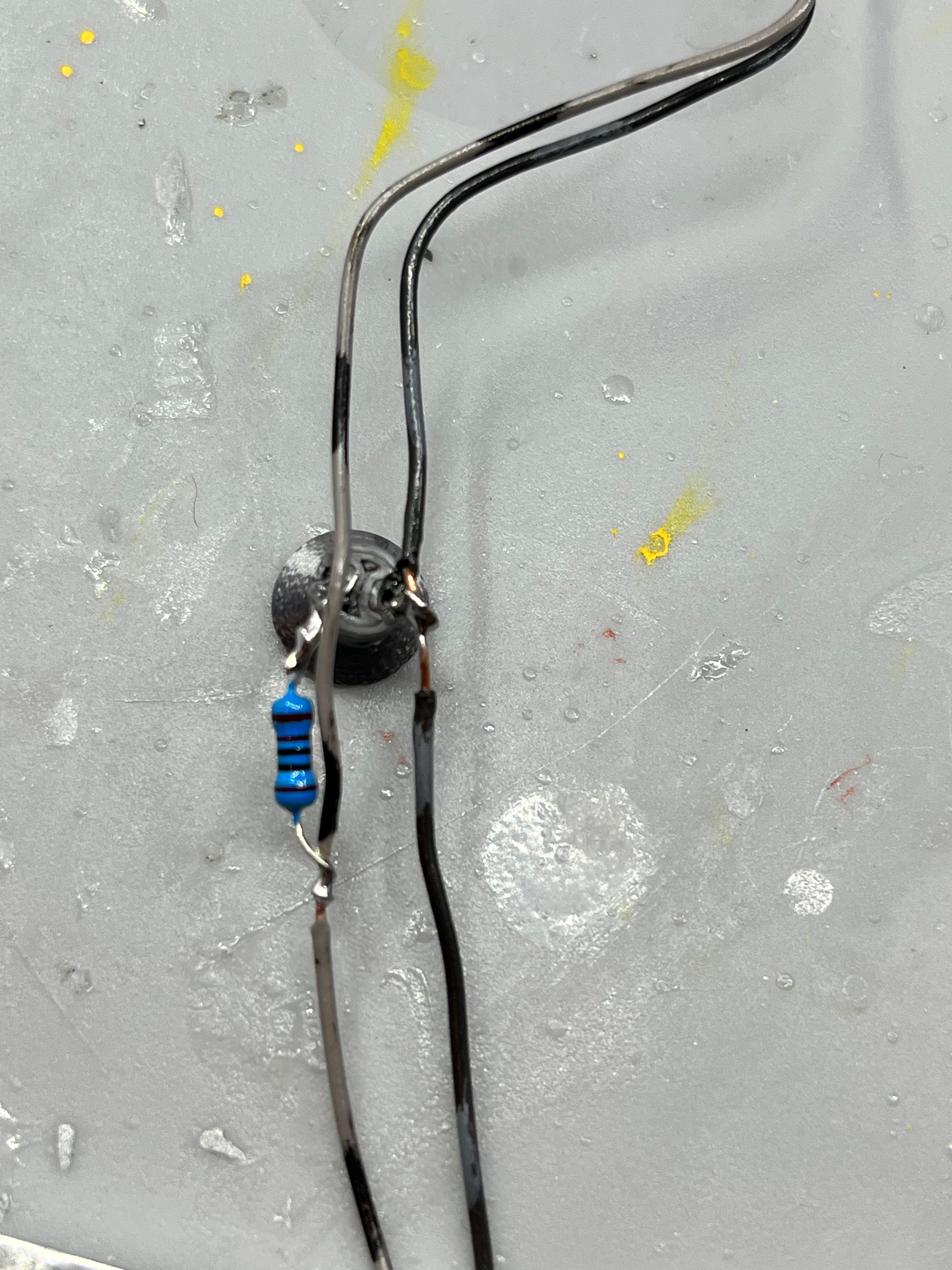
Here are two of the small control panels that are missing from the Aviator67 parts. The SAII Aft Manual Control Panel has three wires, similar to the additions to the Hydropneumatic Consoles.
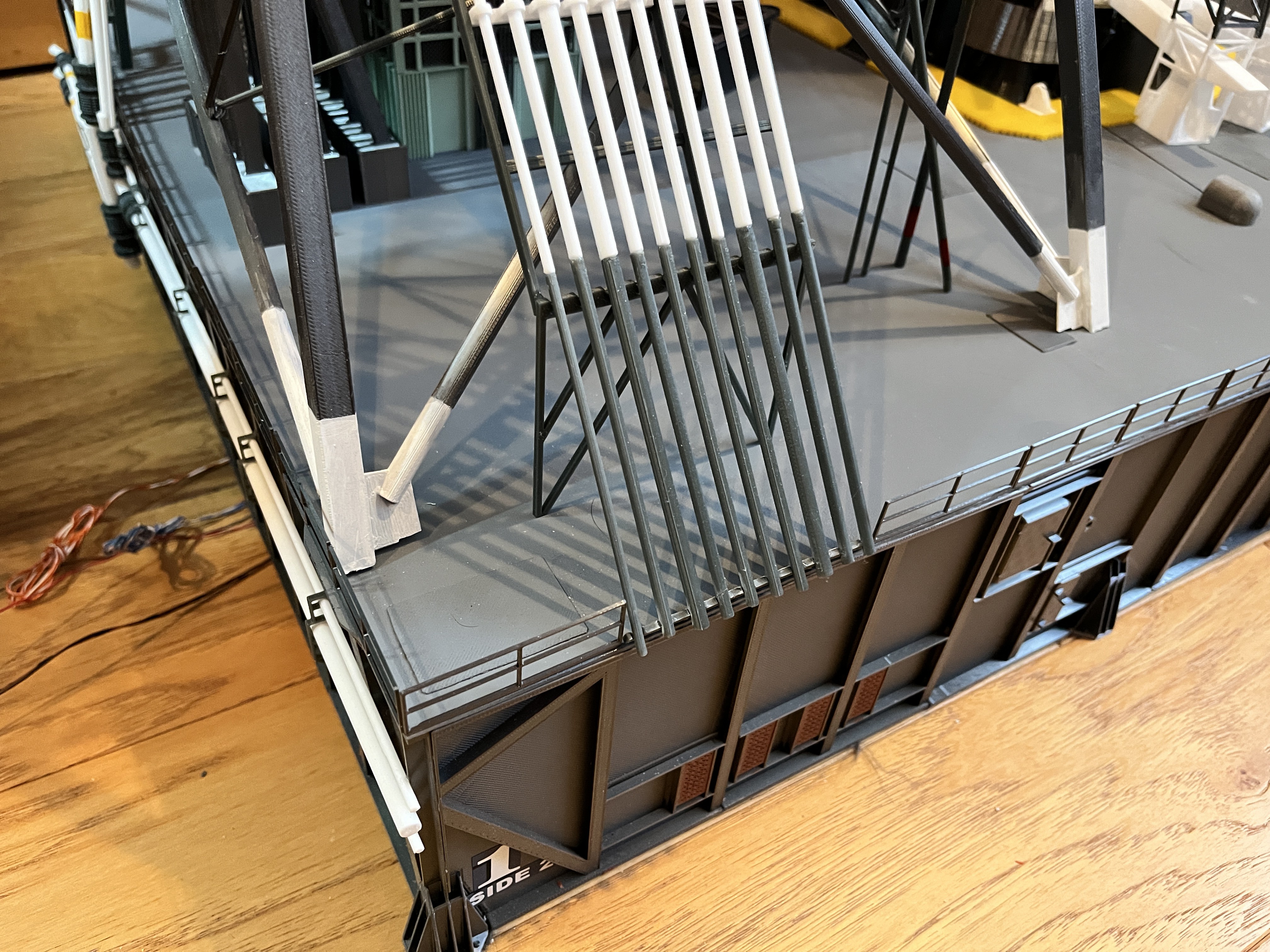
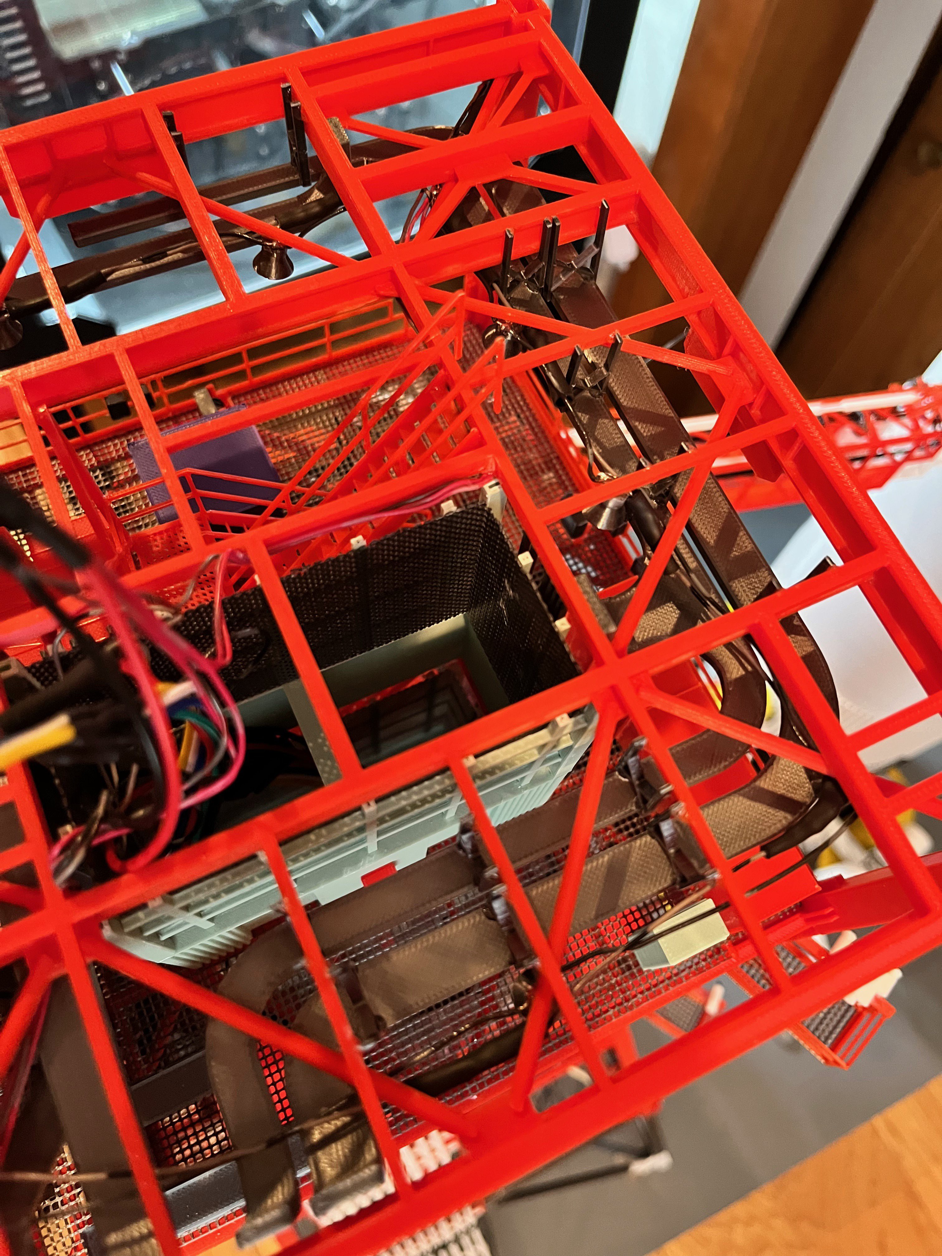
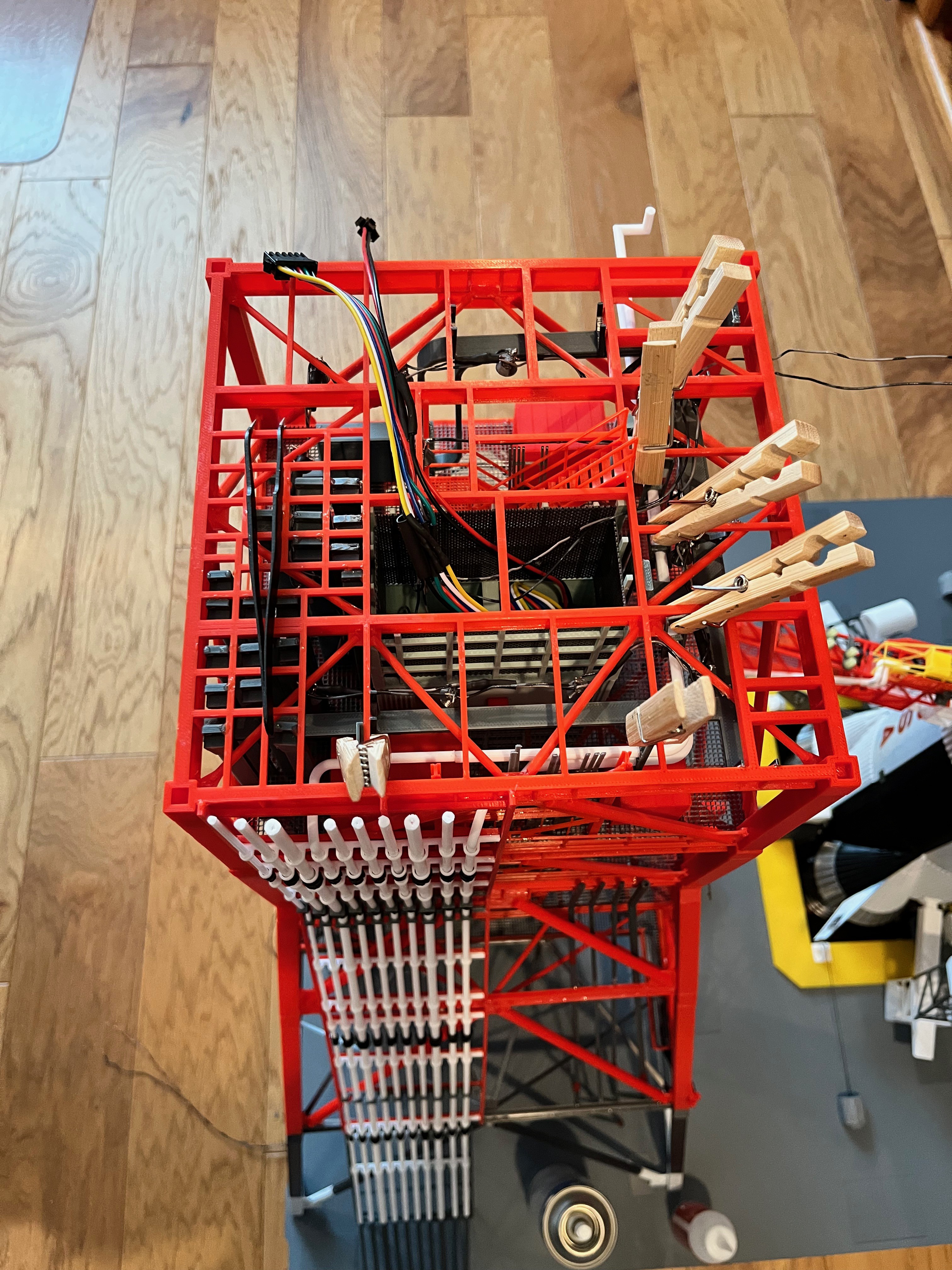
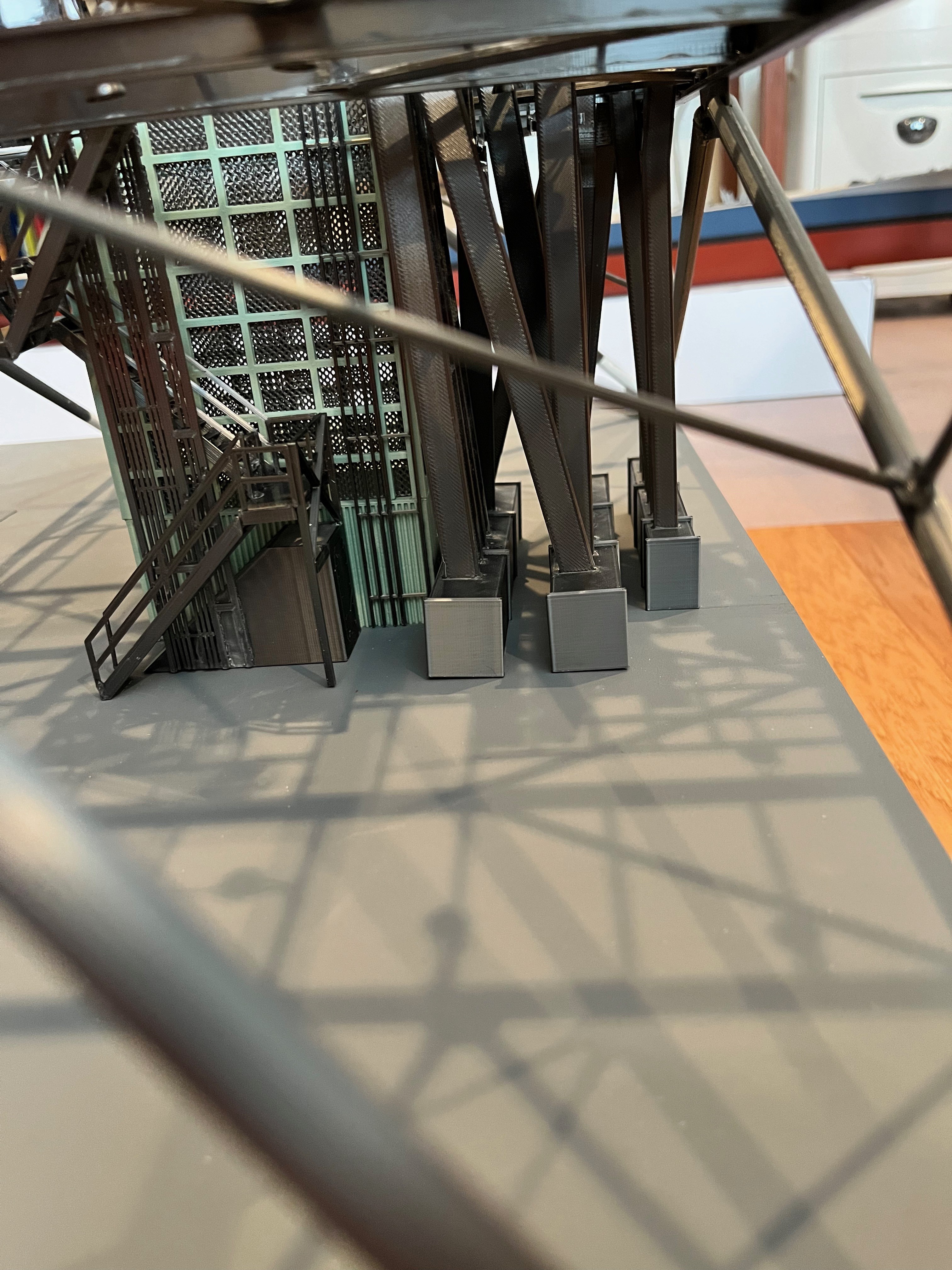
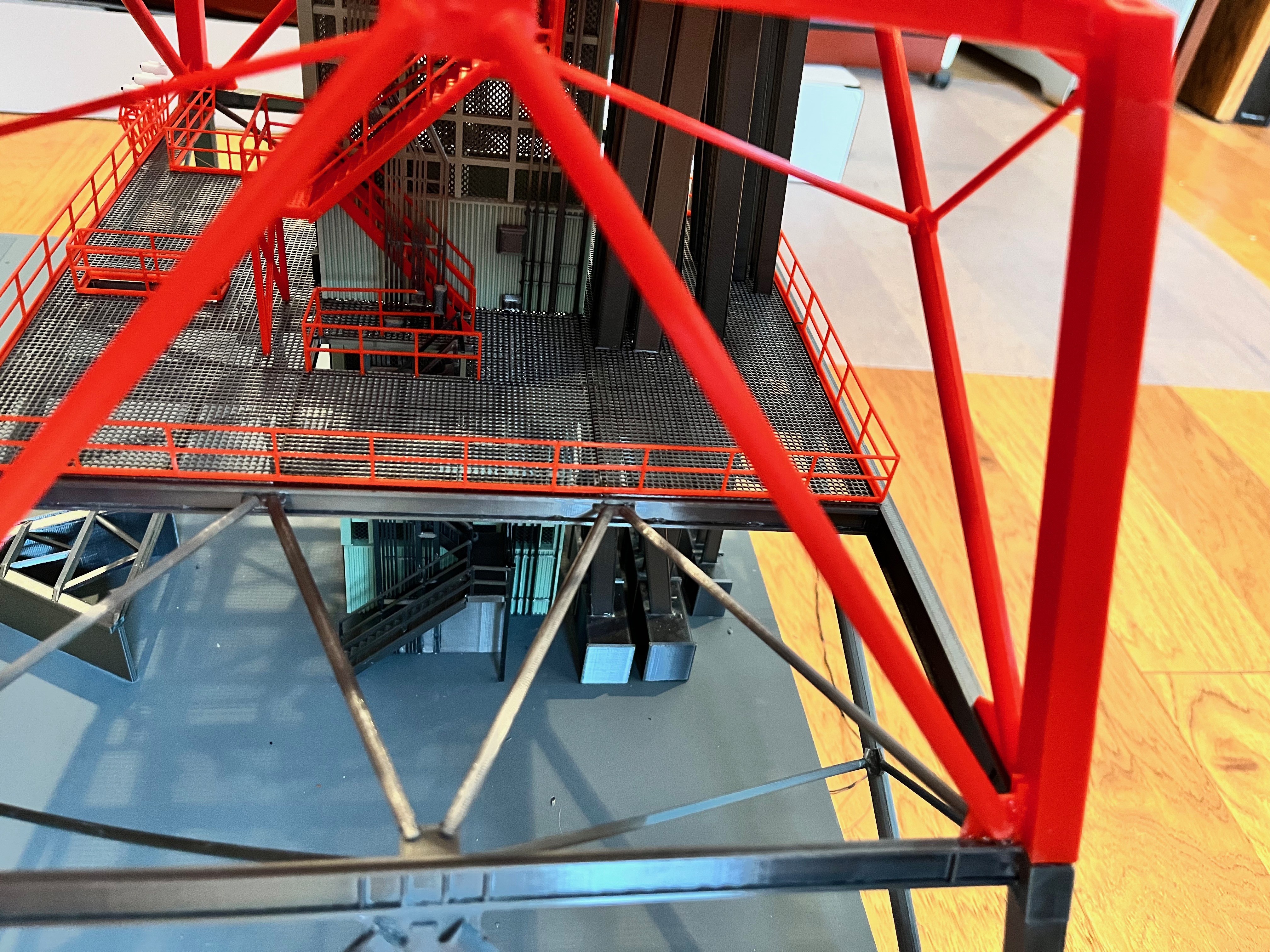
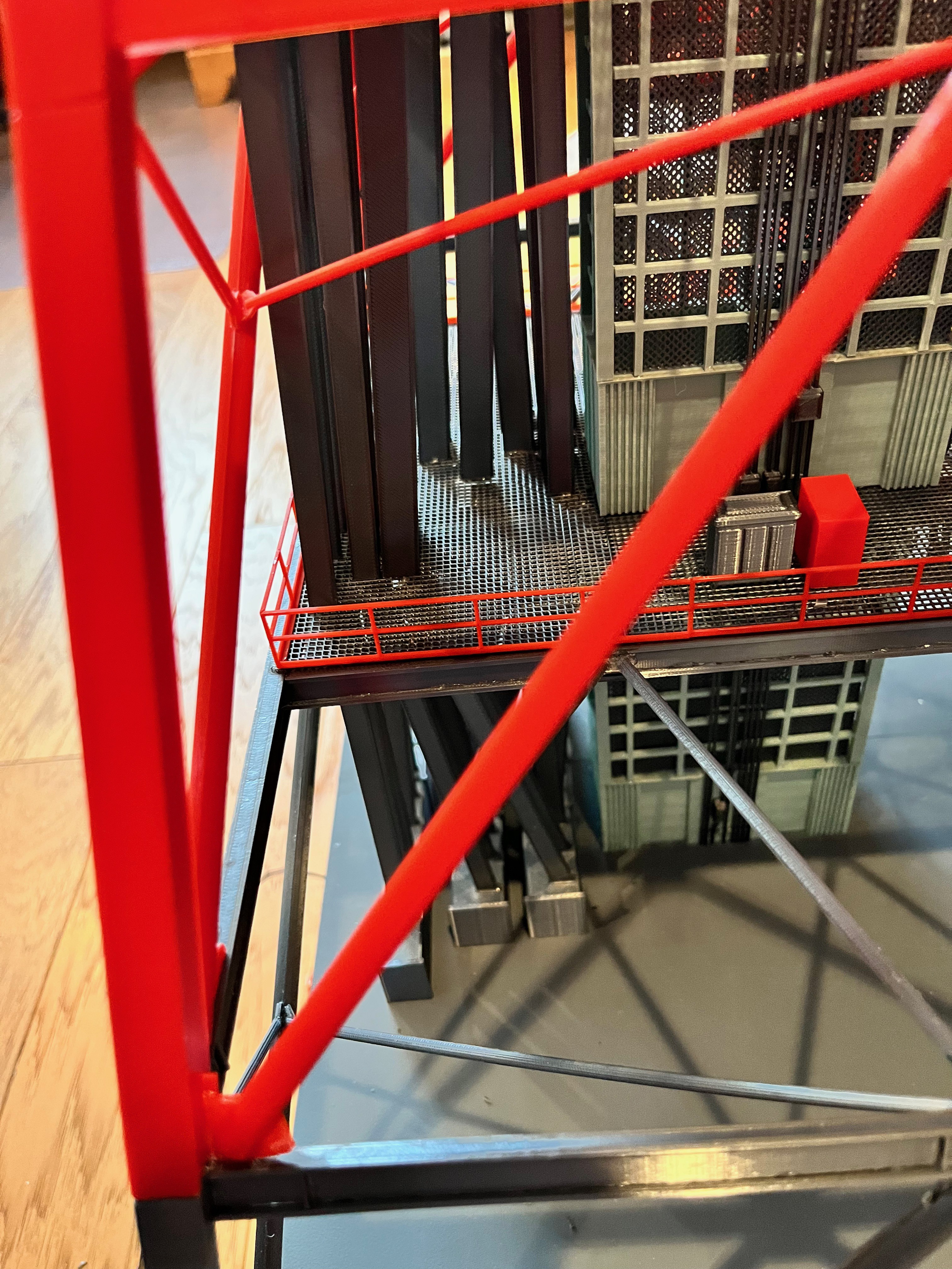
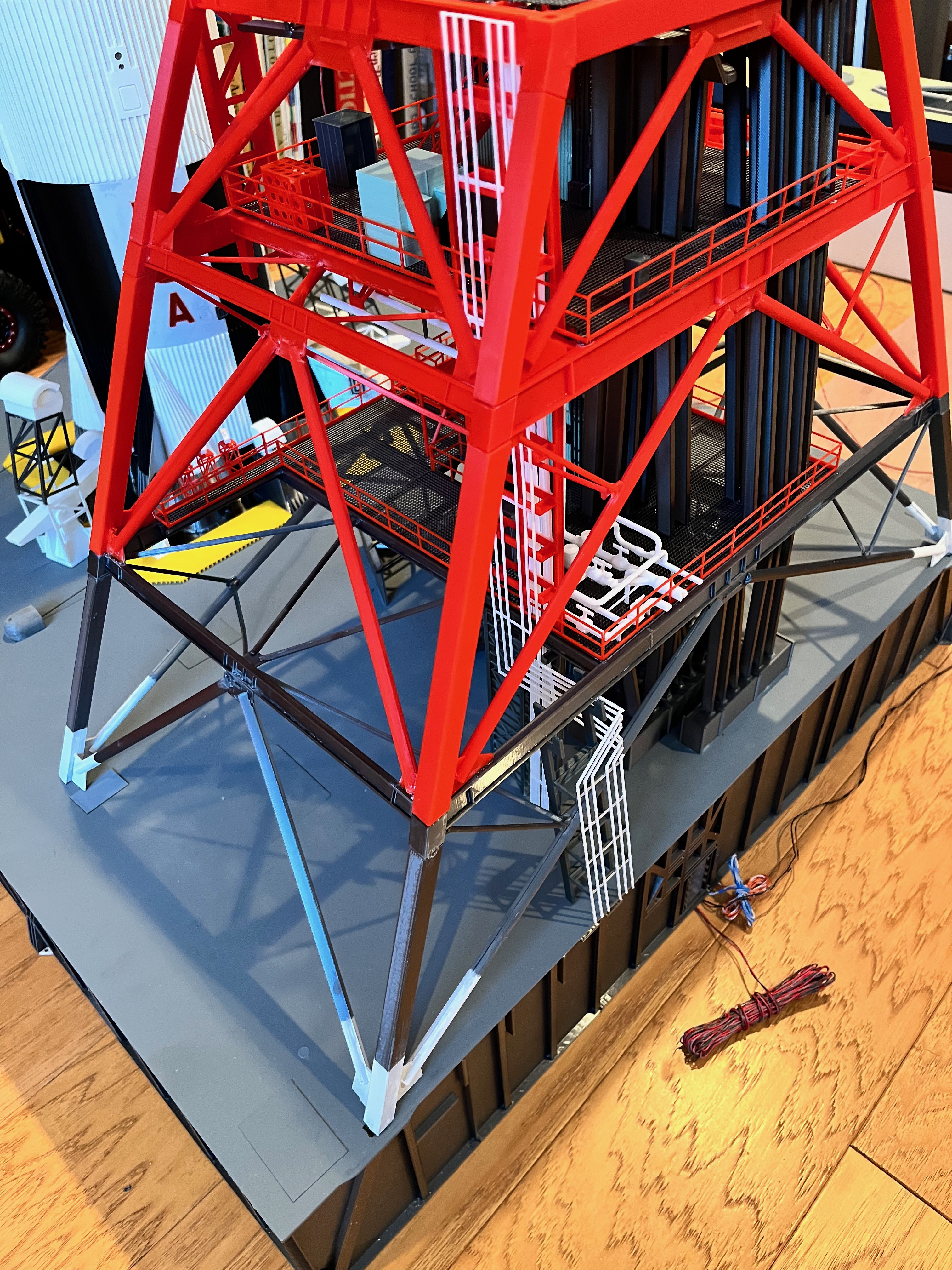
Kind of a busy picture but I have not shown much of the under floor cable trays. This is the cable trays that hang under the level 160 floor. You can see the cable tray hangers. I glue them on with the cable tray in the correct position and then snip off the excess length that sticks up above the floor once the glue dries. I also use the ceiling cable trays held in place with clothes pins while gluing and wiring the lights. The lights go on and then with the floor in place the cable trays go on.
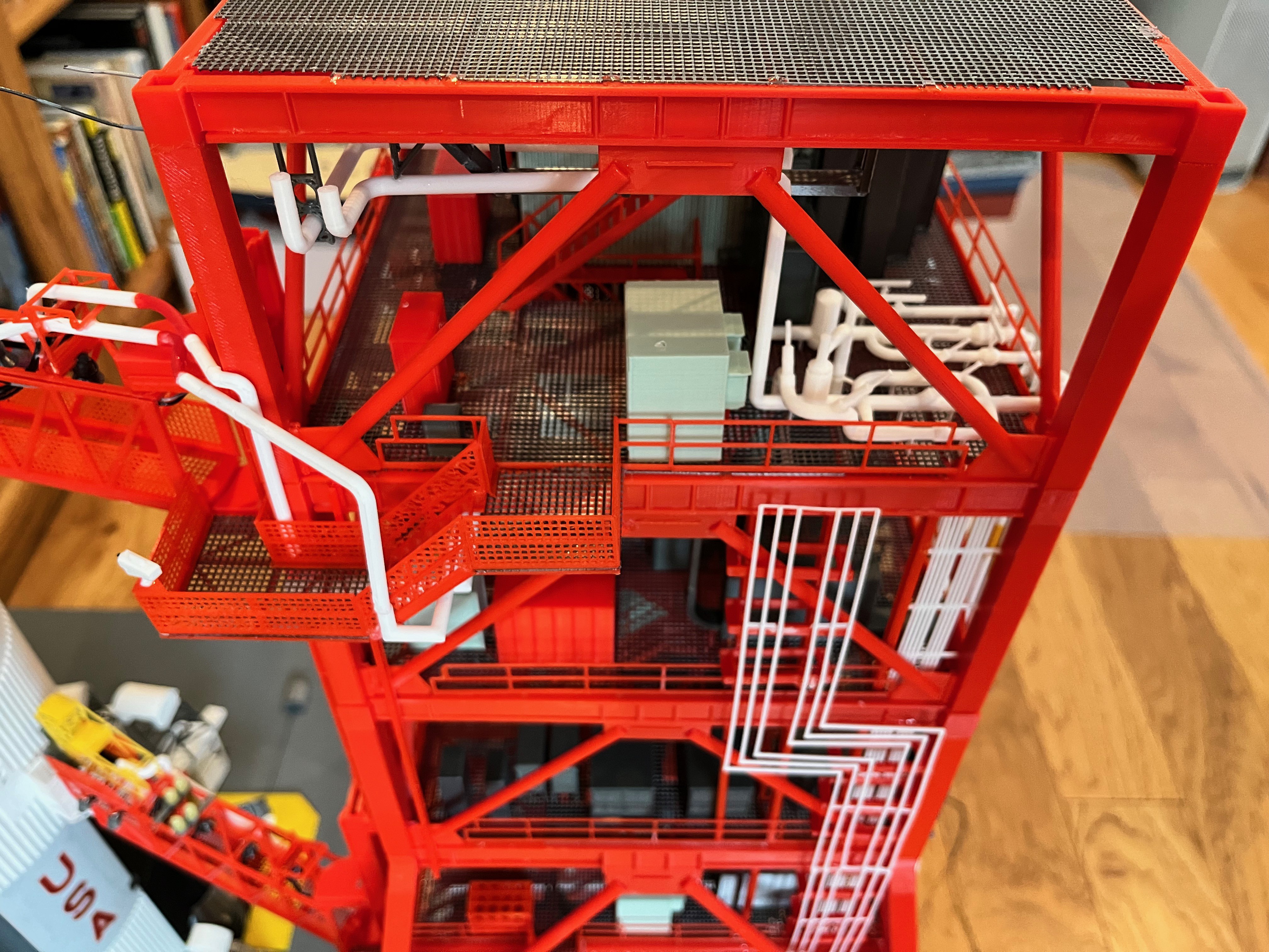
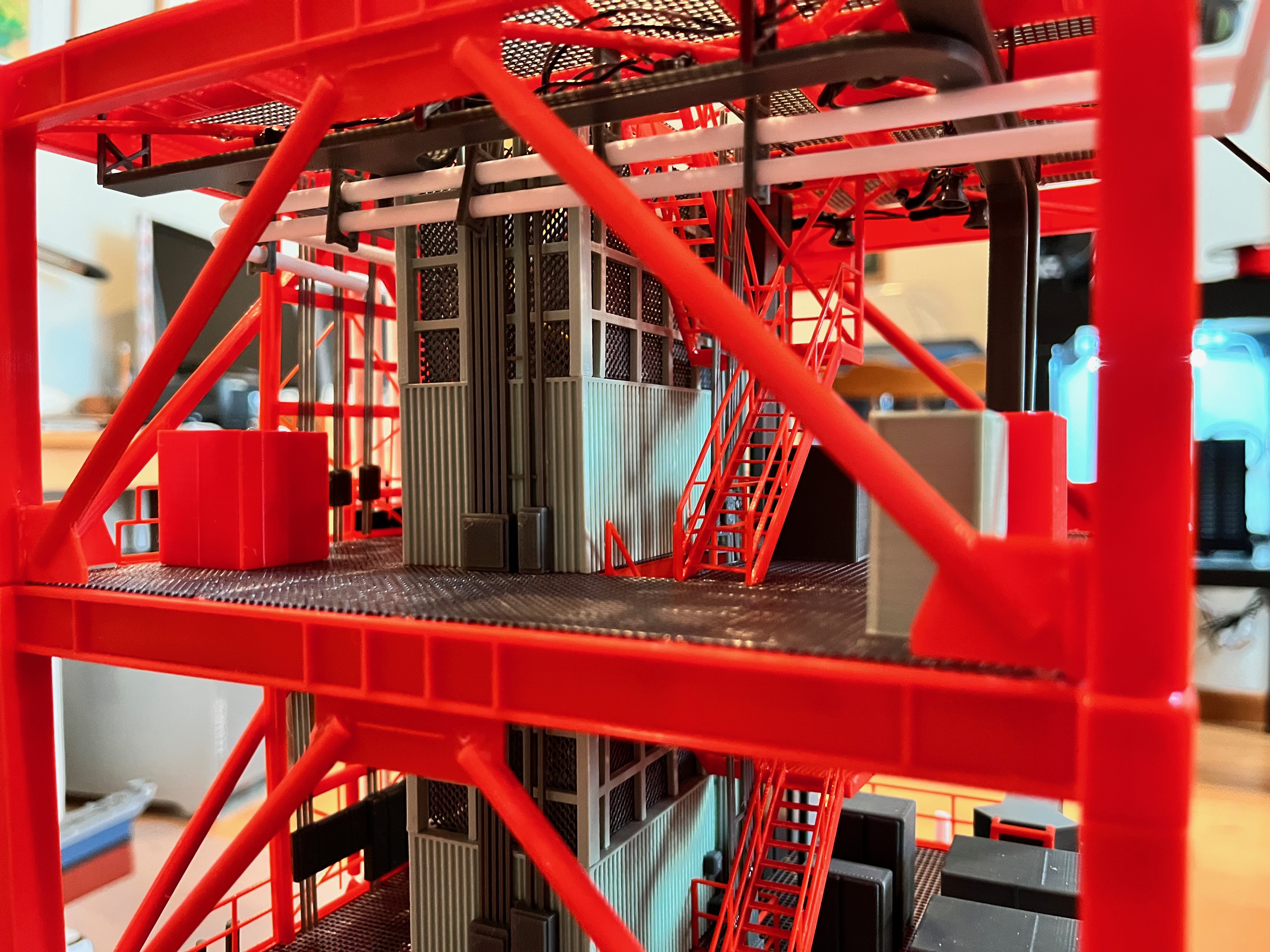
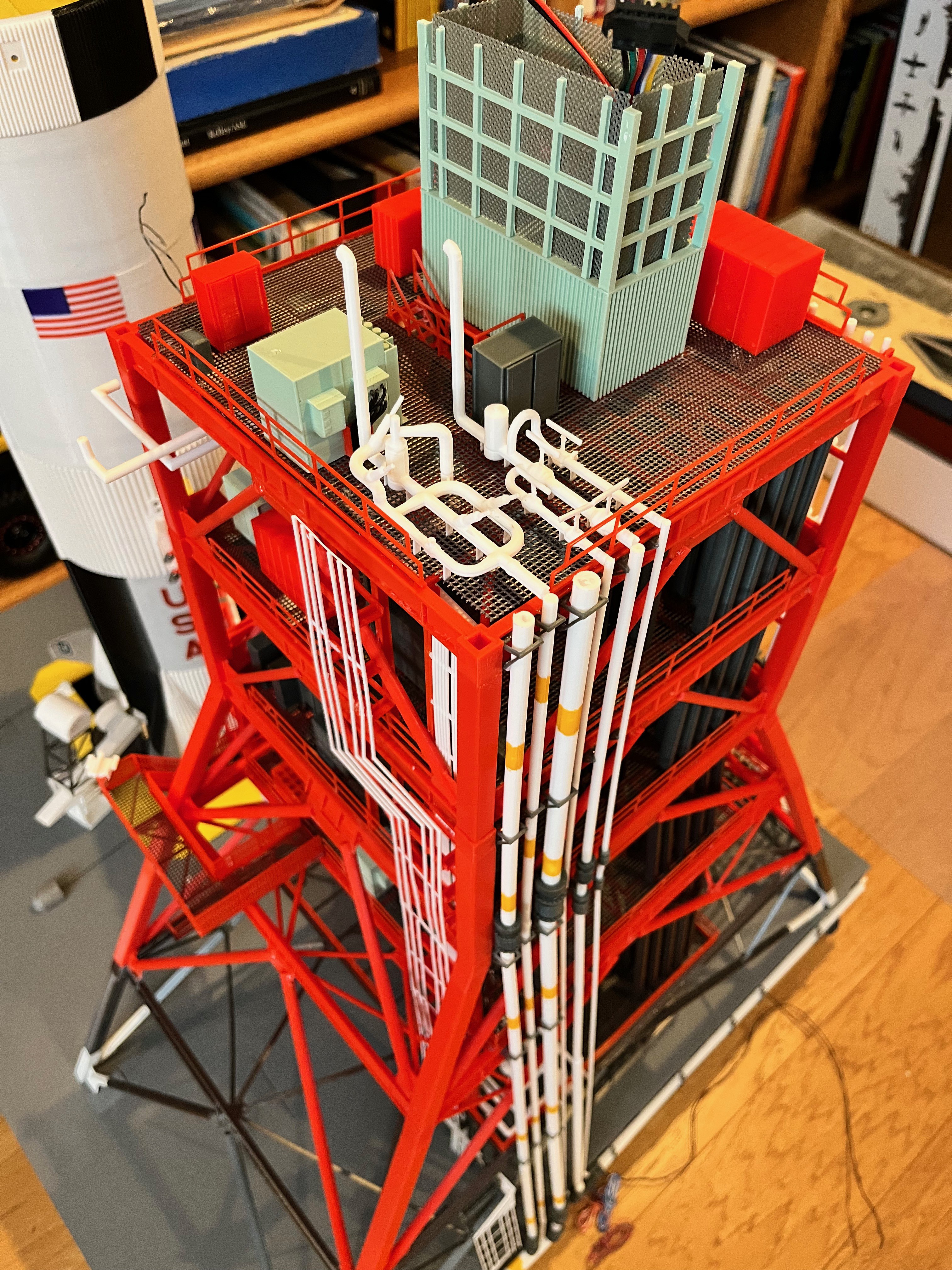
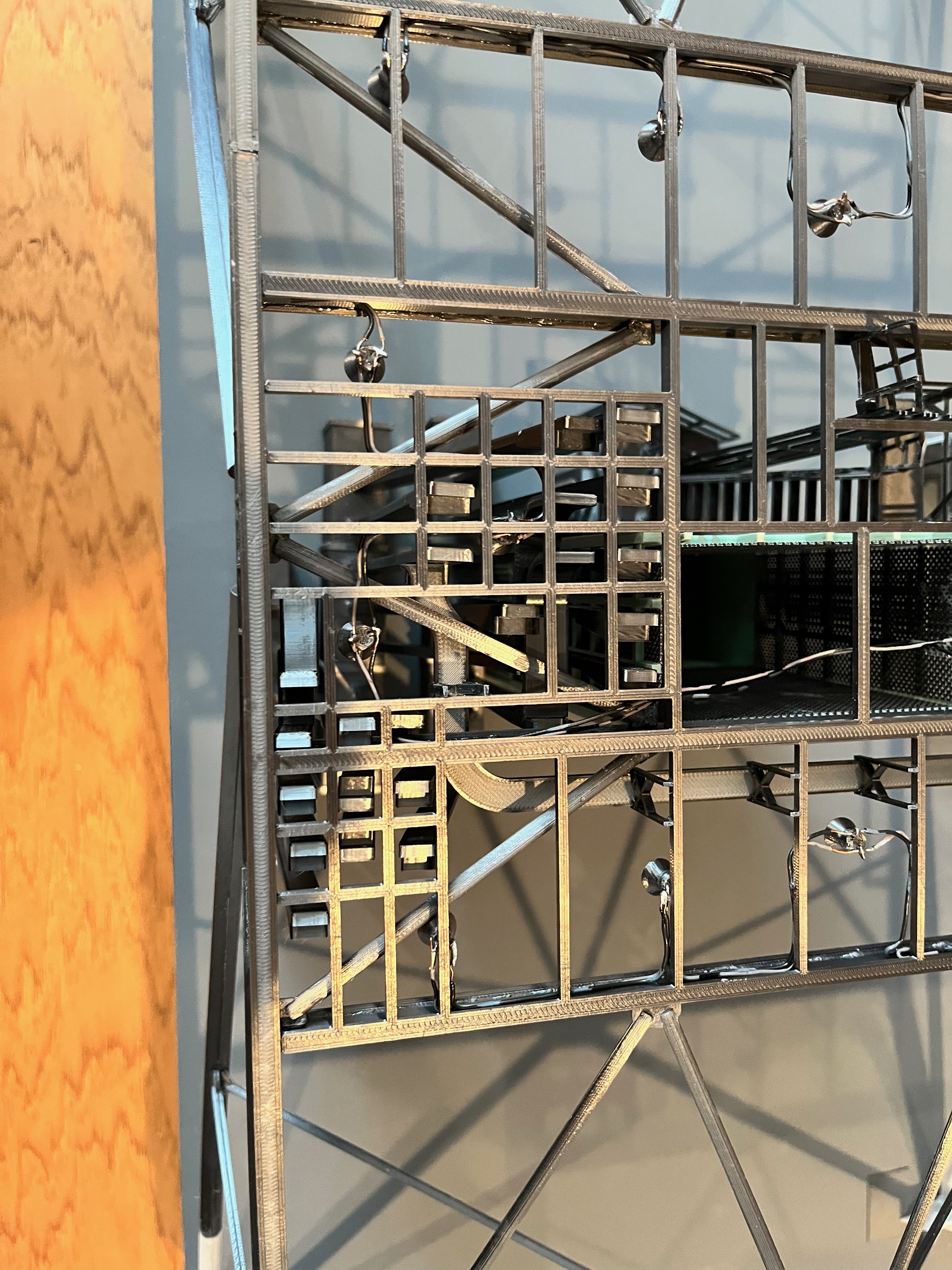
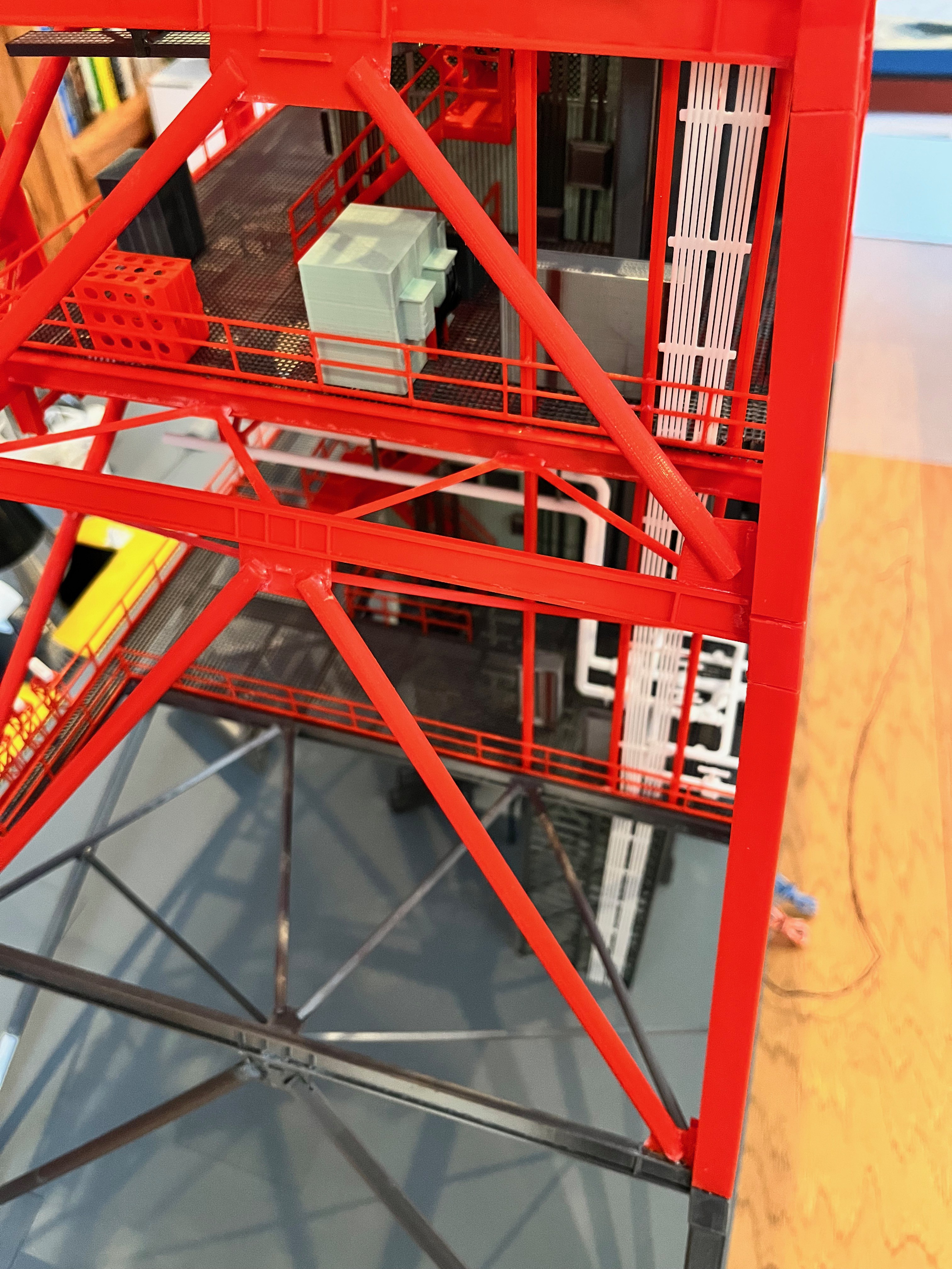
I'm to the point now where I have to stand to add parts to the model. Before long I expect to have to use a step stool. This is a picture of the equipment on level 160.
I'm working on the Level 190 structure that holds pipes. Unfortunately this mid-level is right where removable sections #3 and #4 meet. As a result, part of this structure will attach to the floor of L180 and part will hang from the ceiling of L200. As soon as I print the potion that glues to the L180 floor I will publish all those parts.
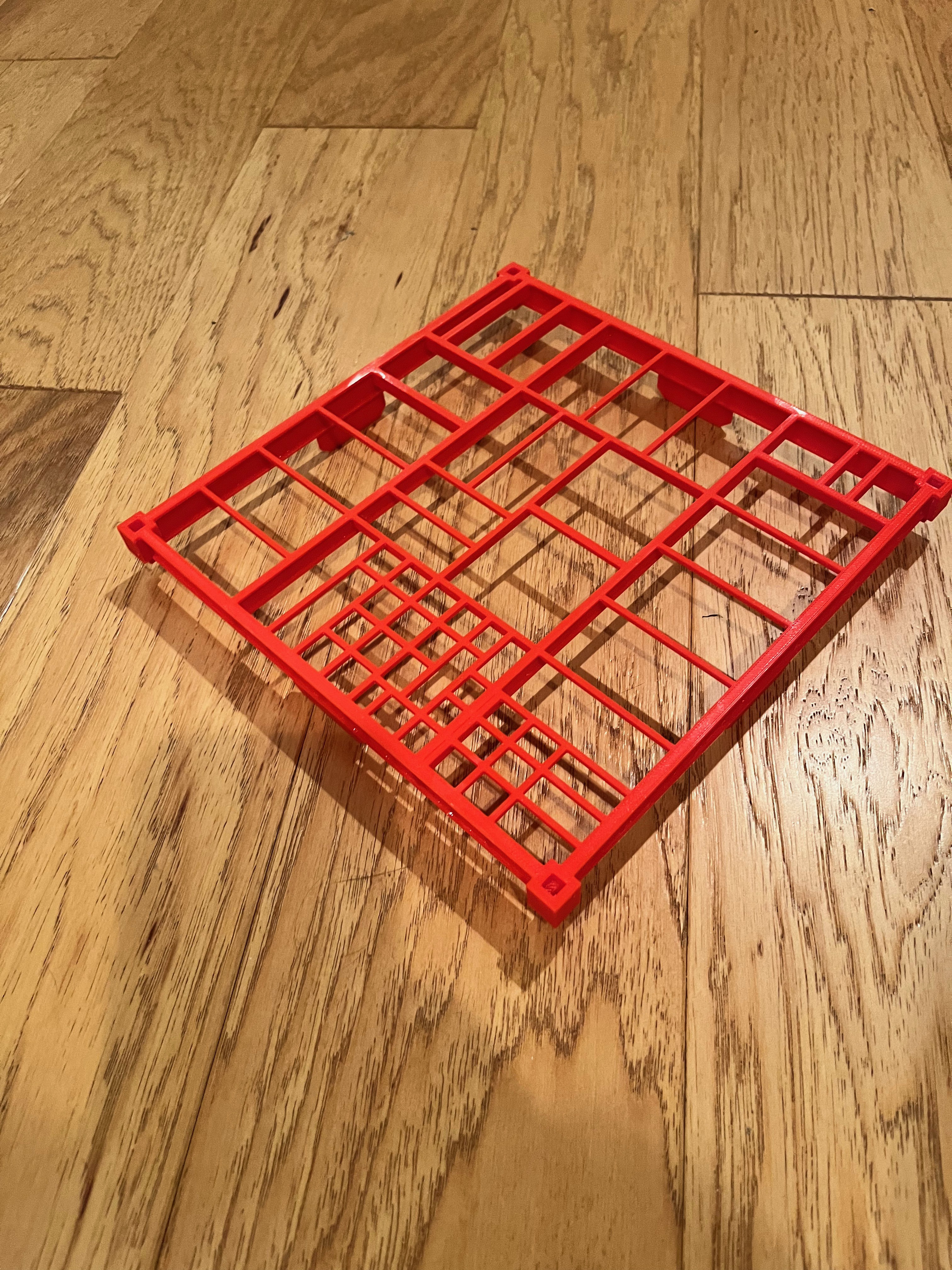
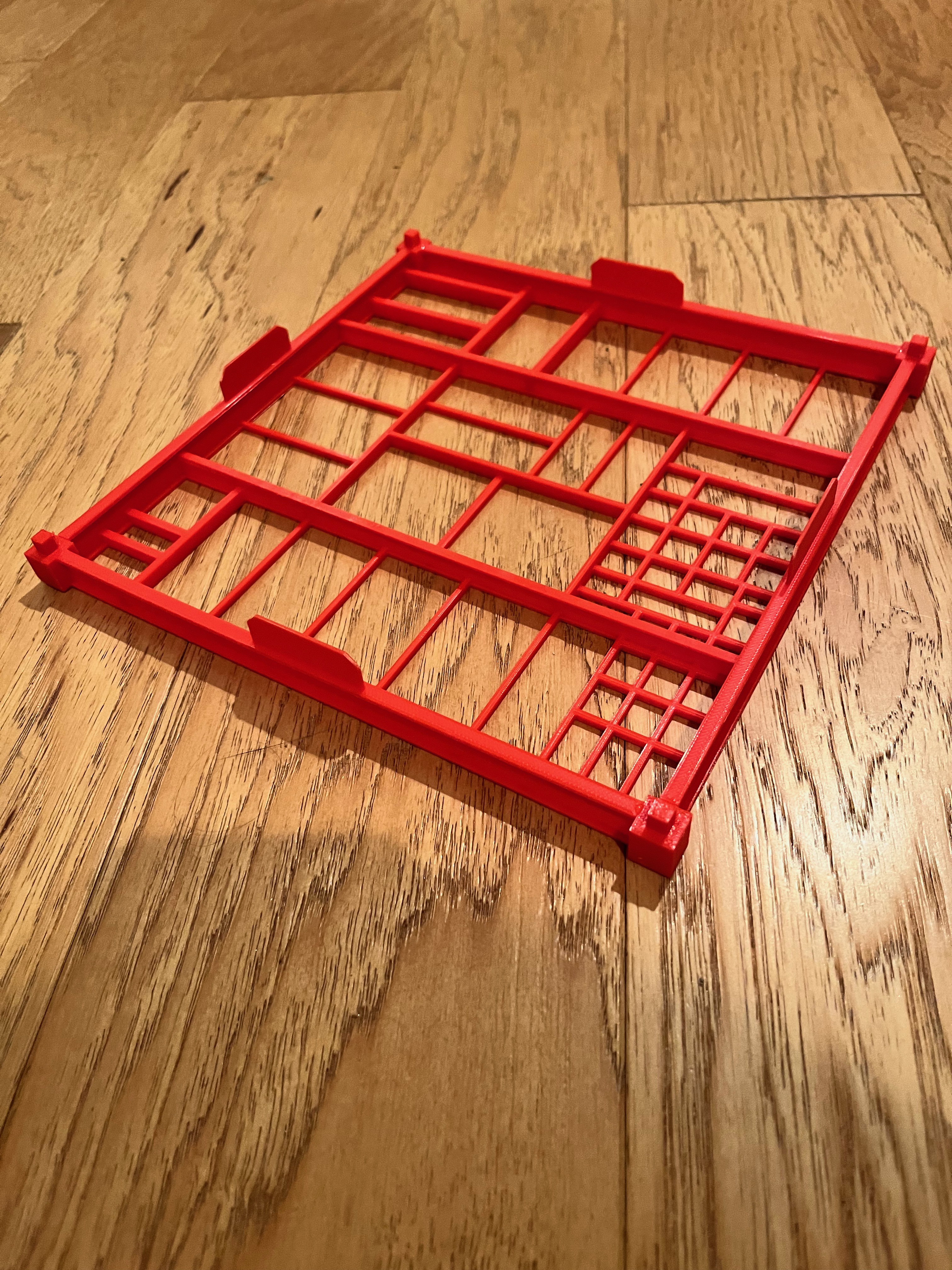
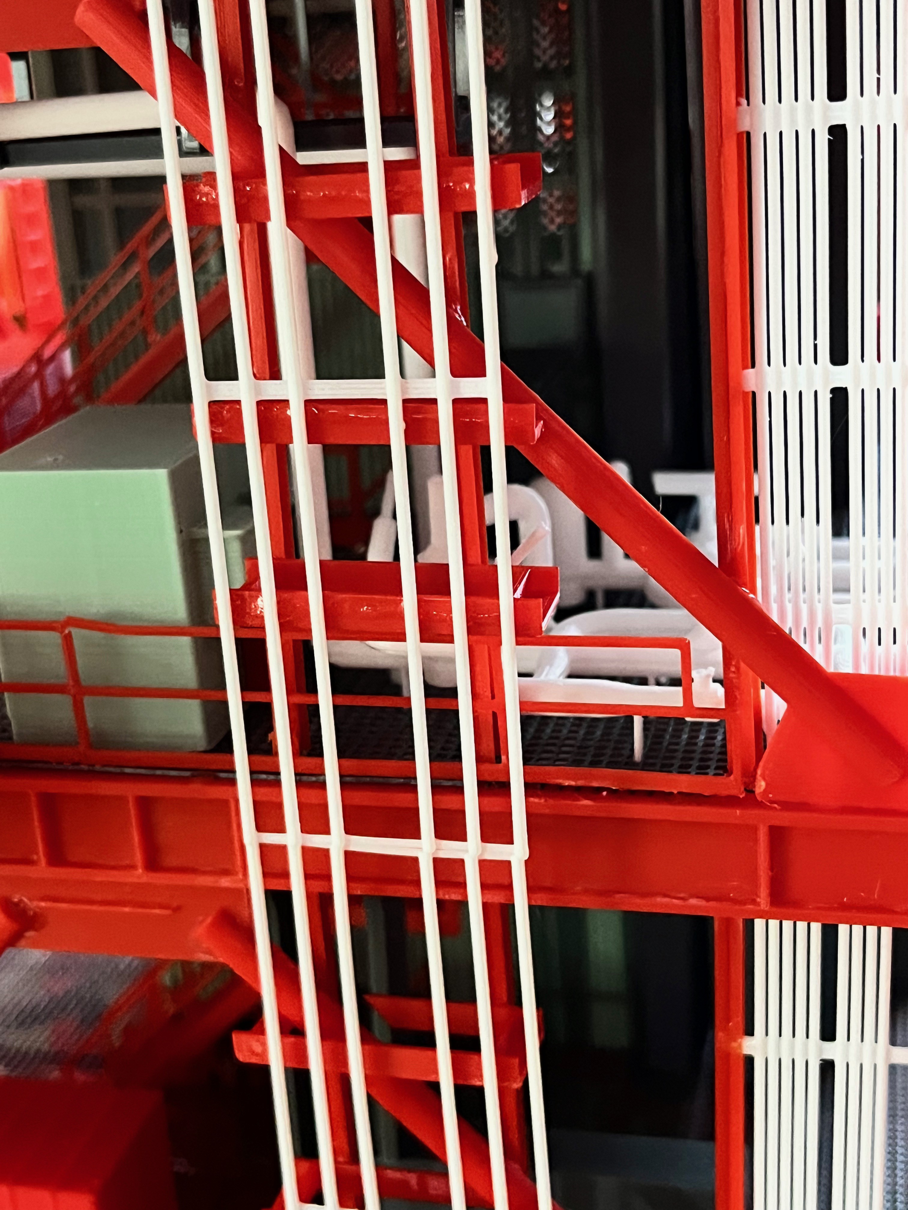
On the Printables web site I was asked why there are no holes in the floor gratings for the cable trays. If you remember about a year ago I tried to print the floor grates with holes in them and was not happy with the results. So I decided to print the floor grating without holes. When gluing the next set of vertical cable trays, once the next level structure is on I glue the bottom of the cable tray to the floor grating below and the top to the floor I-beams above. Once all the cable trays, both vertical and horizontal are glued in along with the stairs, I then glue the upper floor grating on. For the cable trays at the removable section breaks, the cable trays are glued to the upper floor I-beams and not to the lower floor grating. This allows the sections to be removable.
As an example, assume I have already glued on the elevator and equipment that sits on the L160 floor grating. I then glue on the structure for Level 160-180. Next up is the stairs which are glued to both the L180 floor I-beams and the L160 floor grating. Then the vertical cable trays are added. The bottom is glued to the L160 floor grating and the top is glued to the L180 floor I-beams. After that the horizontal cable trays are added as they are typically glued to one or more vertical cable tray. The tray hangers are made intentionally long so that the cable tray can be positioned and the excess length is cut off once the glue dries. Now the L180 floor grating can be glued on top of the L180 floor I-beam structure.
I hope this helps. The model is so complex, creating a step by step instruction manual would take thousands of pages. Once you get started you will notice the steps become repetitive.
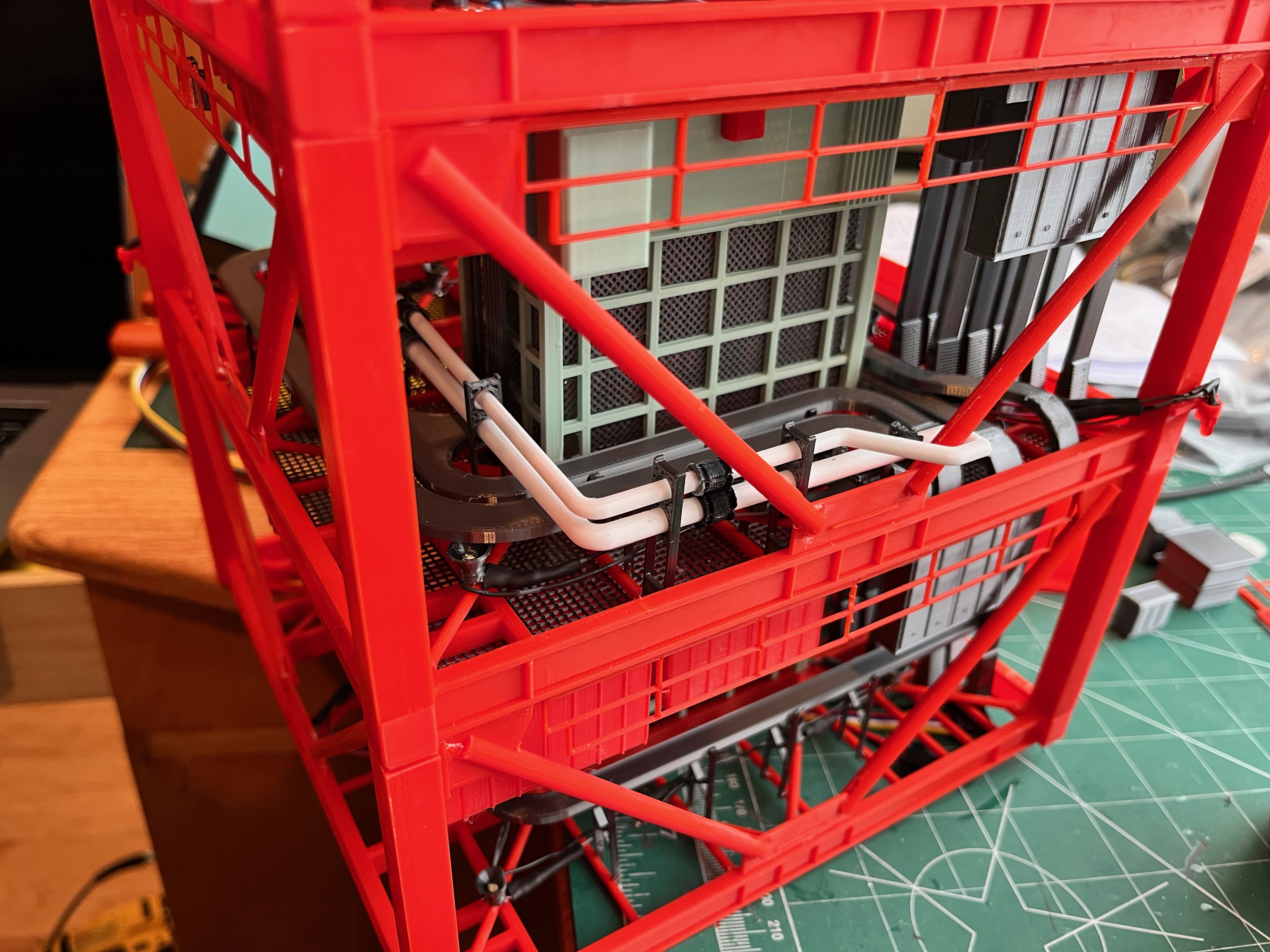
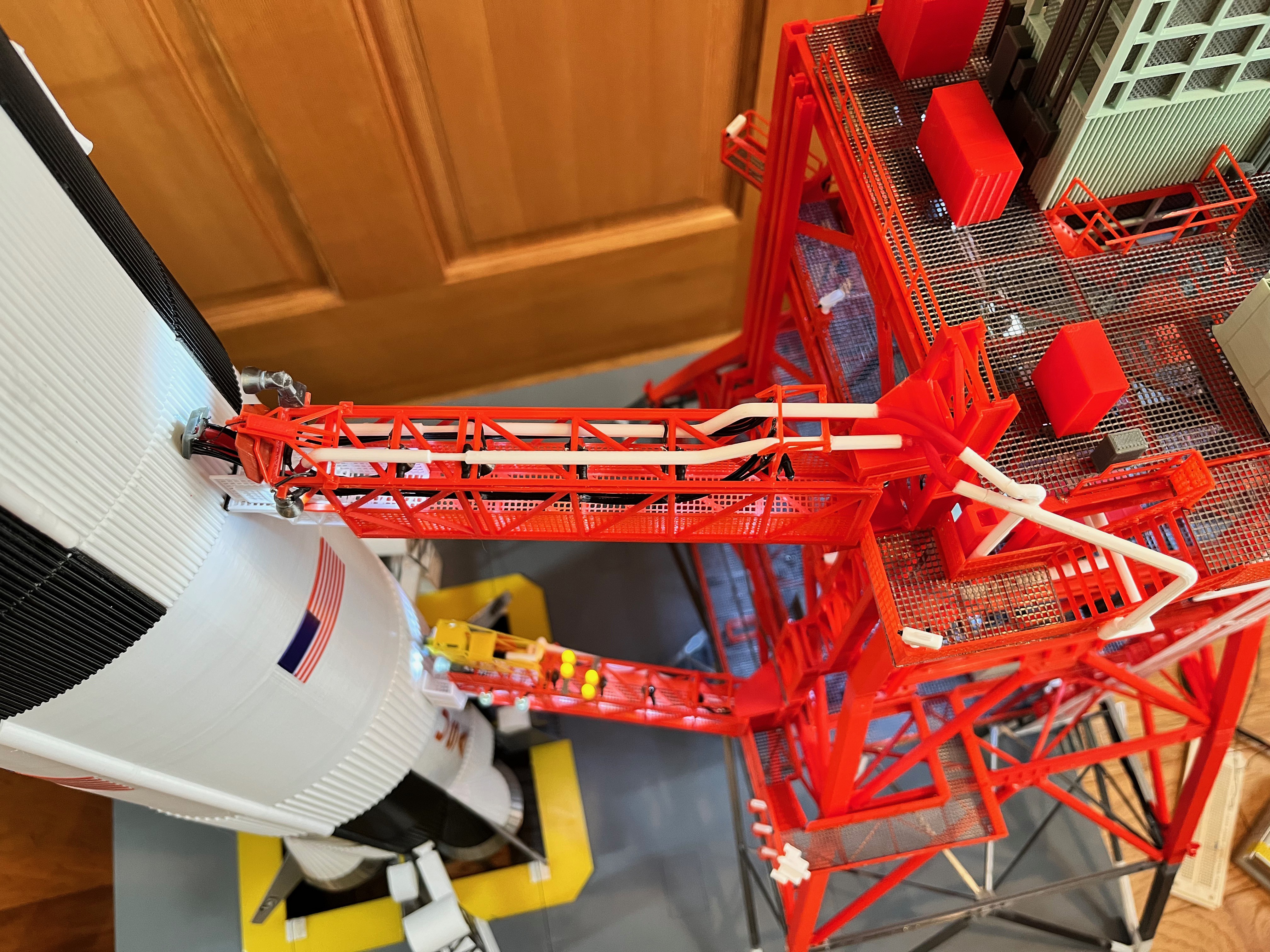
At L140-160 there are ECS pipes that run under the ceiling over to Swing Arm #4. I forgot to add these when it was easy. This will now test my skills at adding pieces in tight spaces. Fortunately I can remove this section of the tower and add the pieces with this section upside down which should help. These pieces have been added to the spreadsheet and the Pipe Side 2 model.
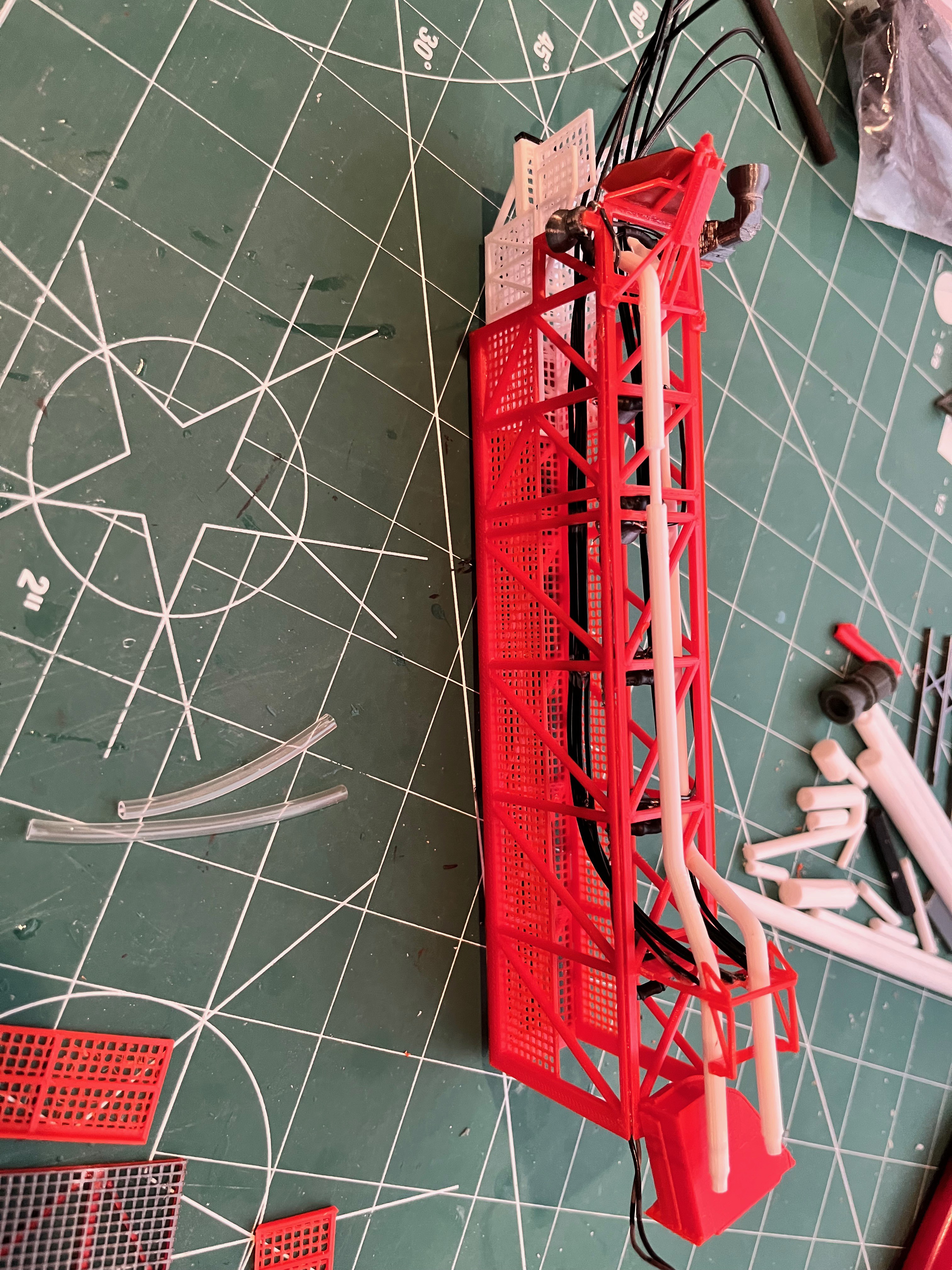
Here are the E5/6 pipes running along the ceiling just under the cable trays, the ones I forgot to add when access was easy. This was fairly easy with section #3 of the tower removed and upside down.
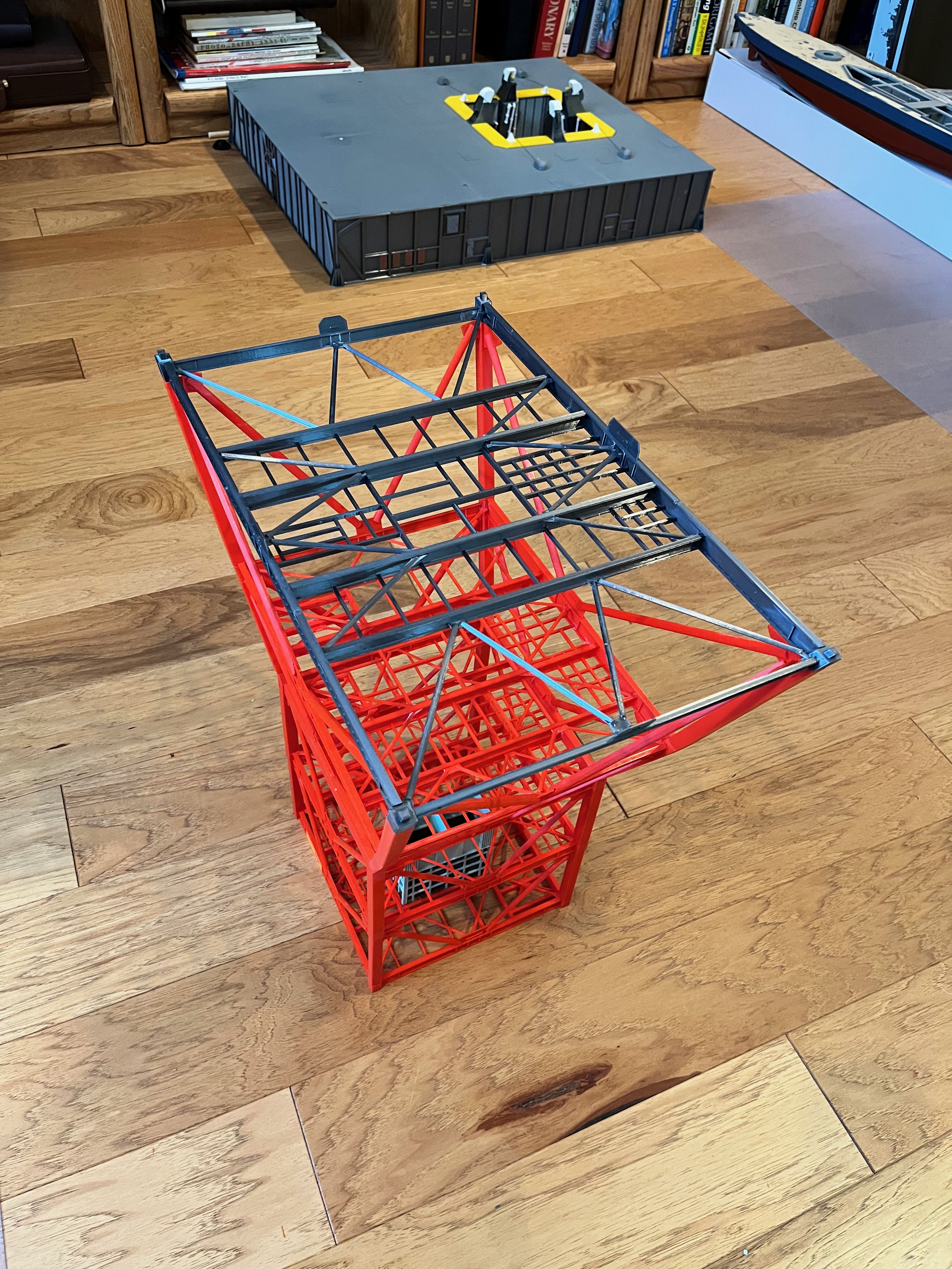
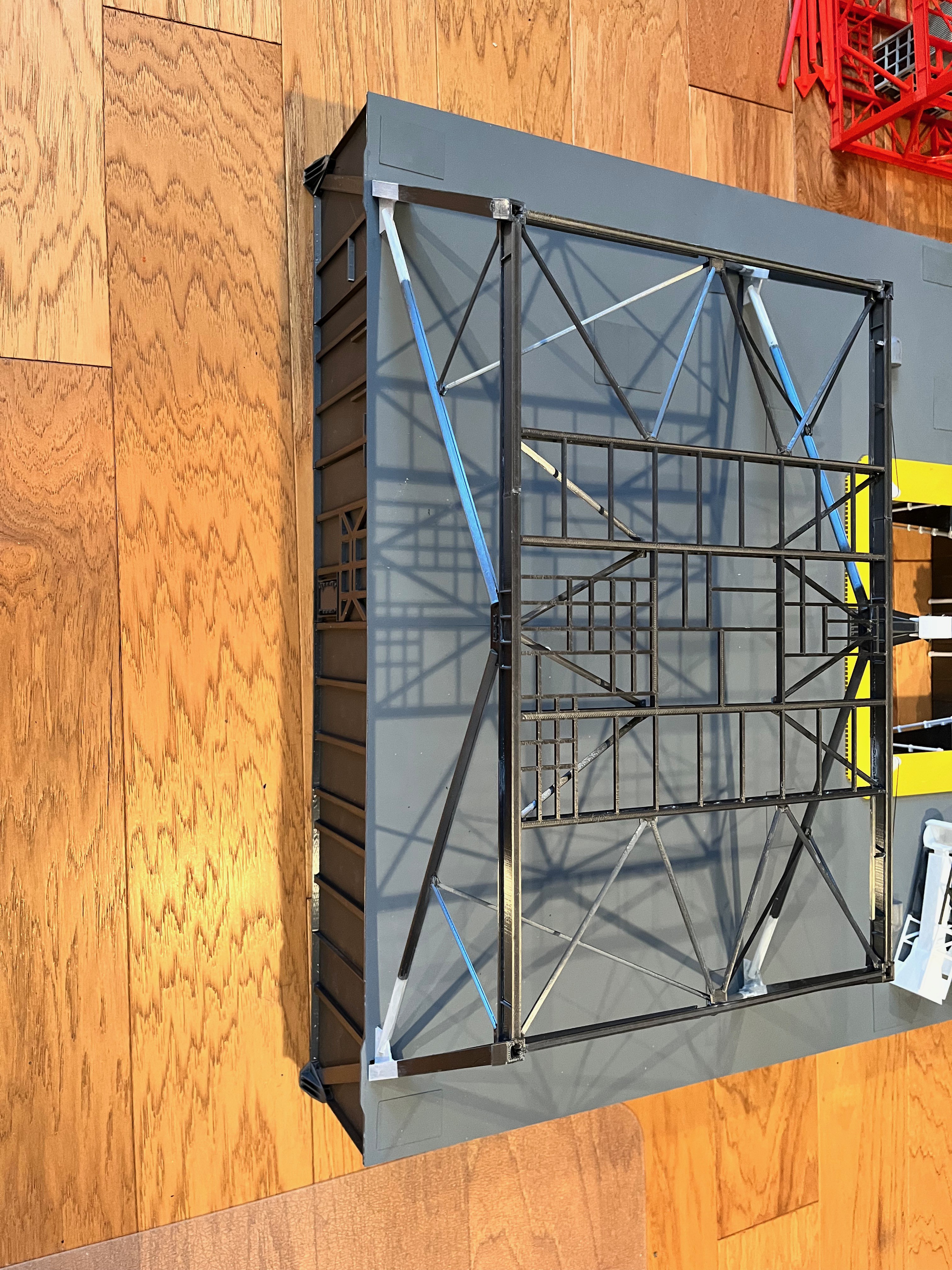
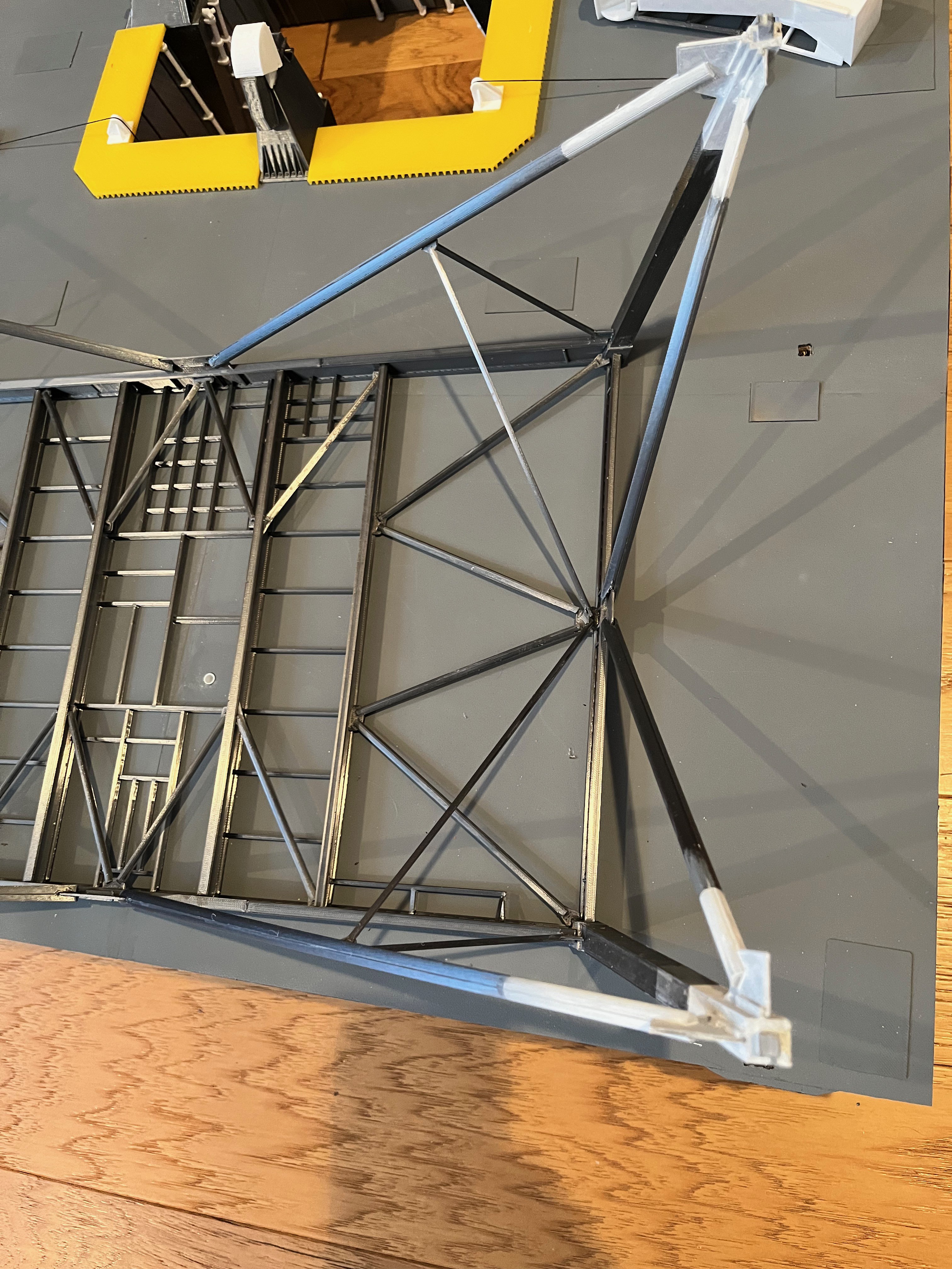
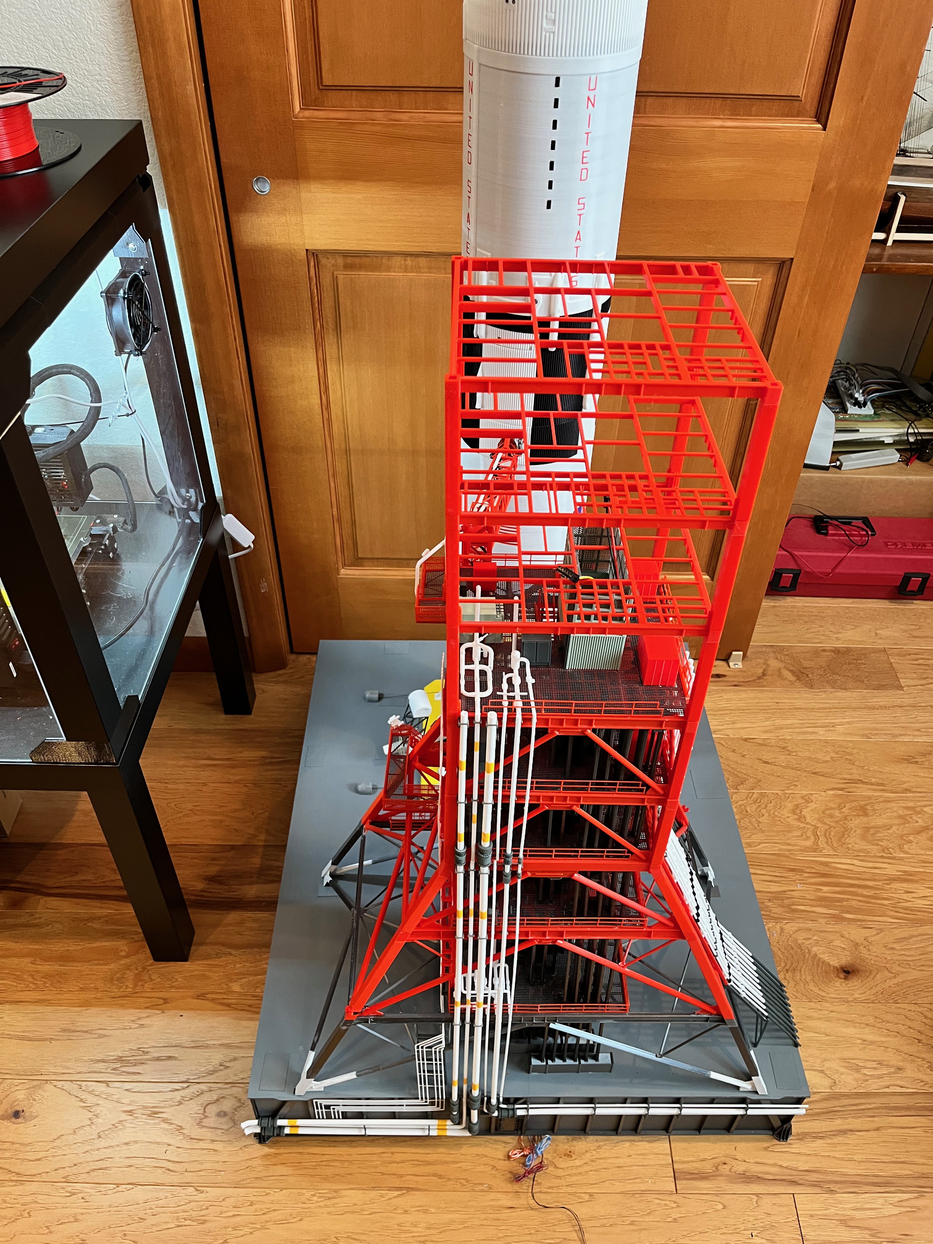
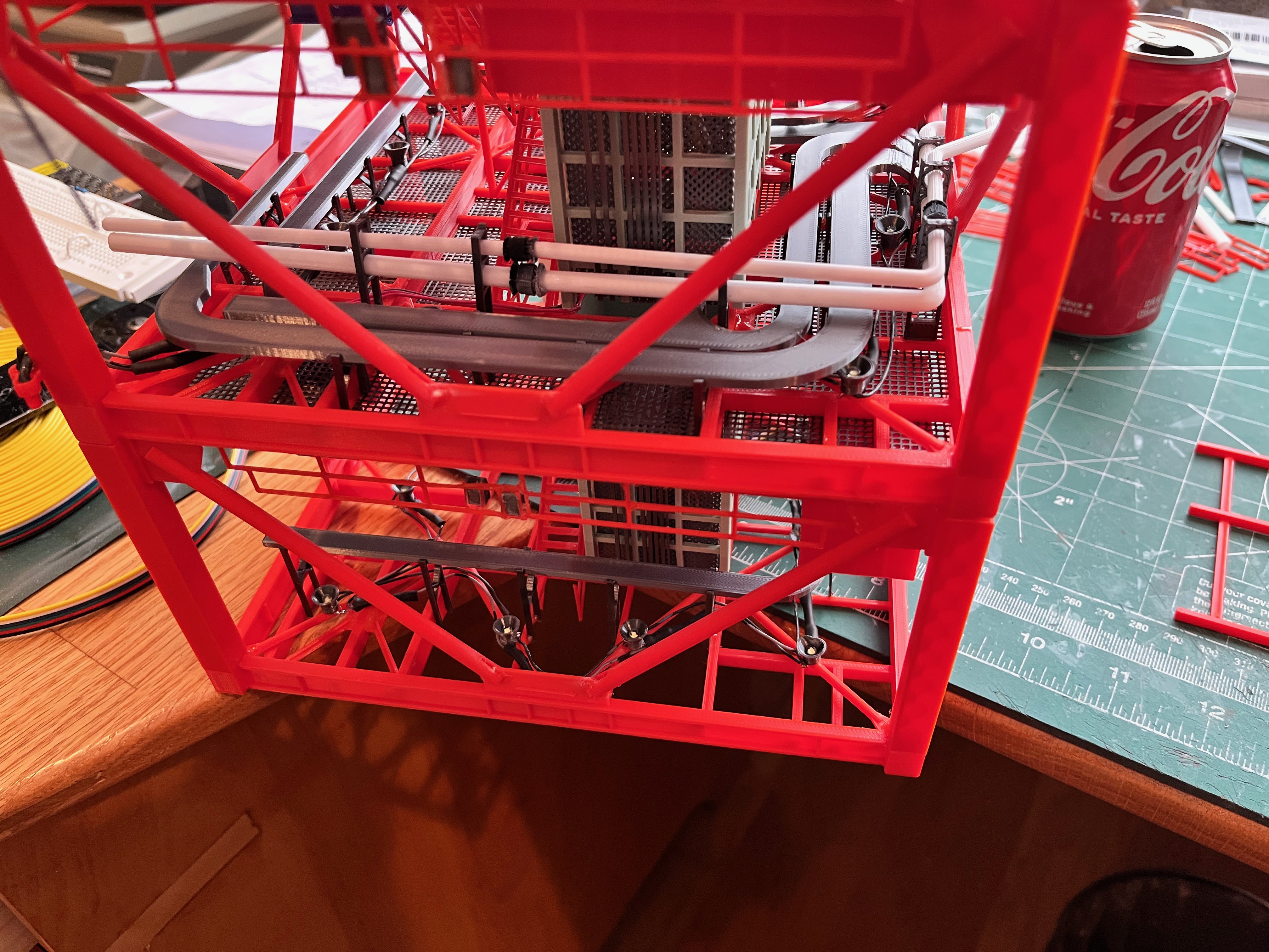
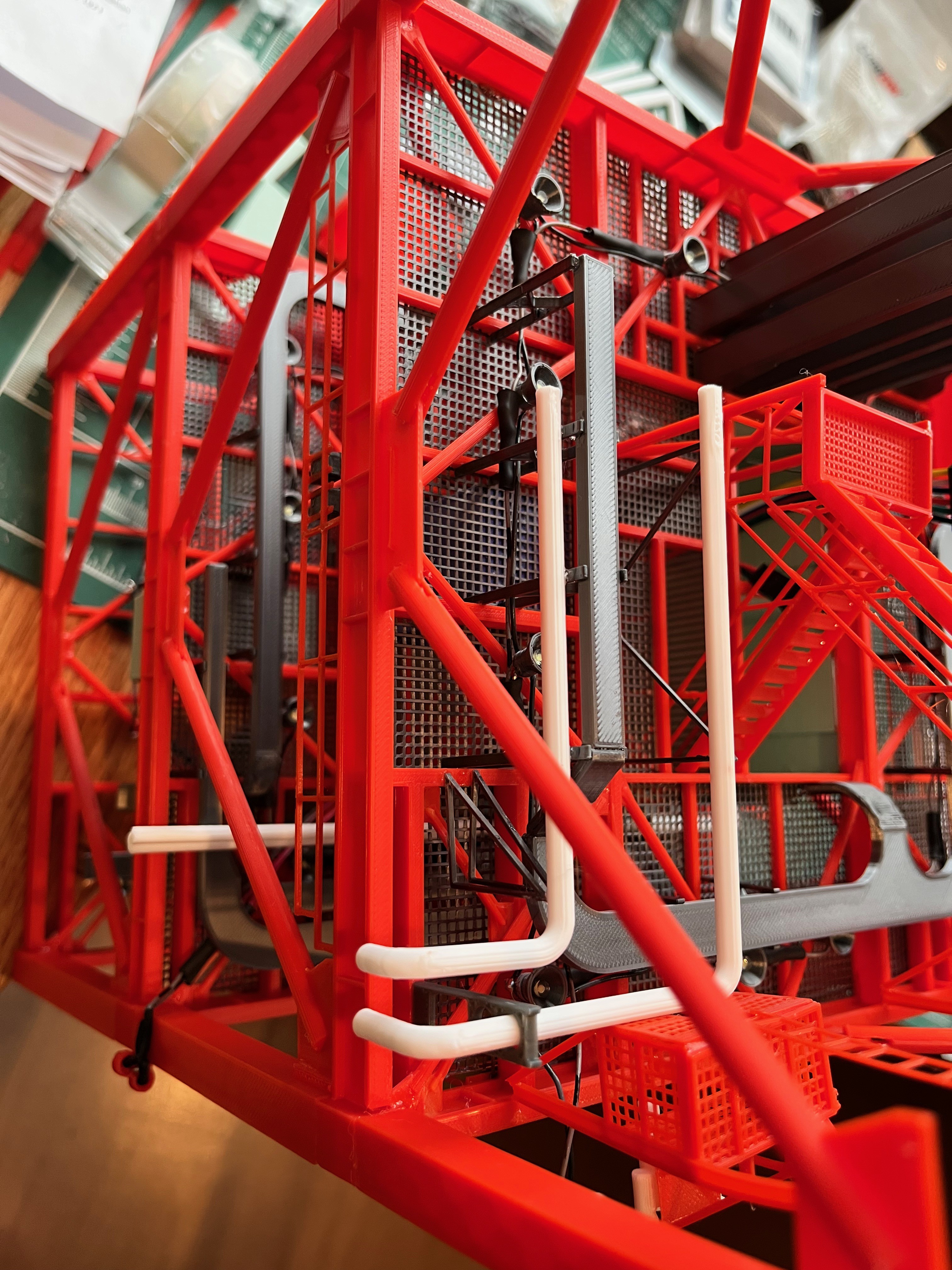
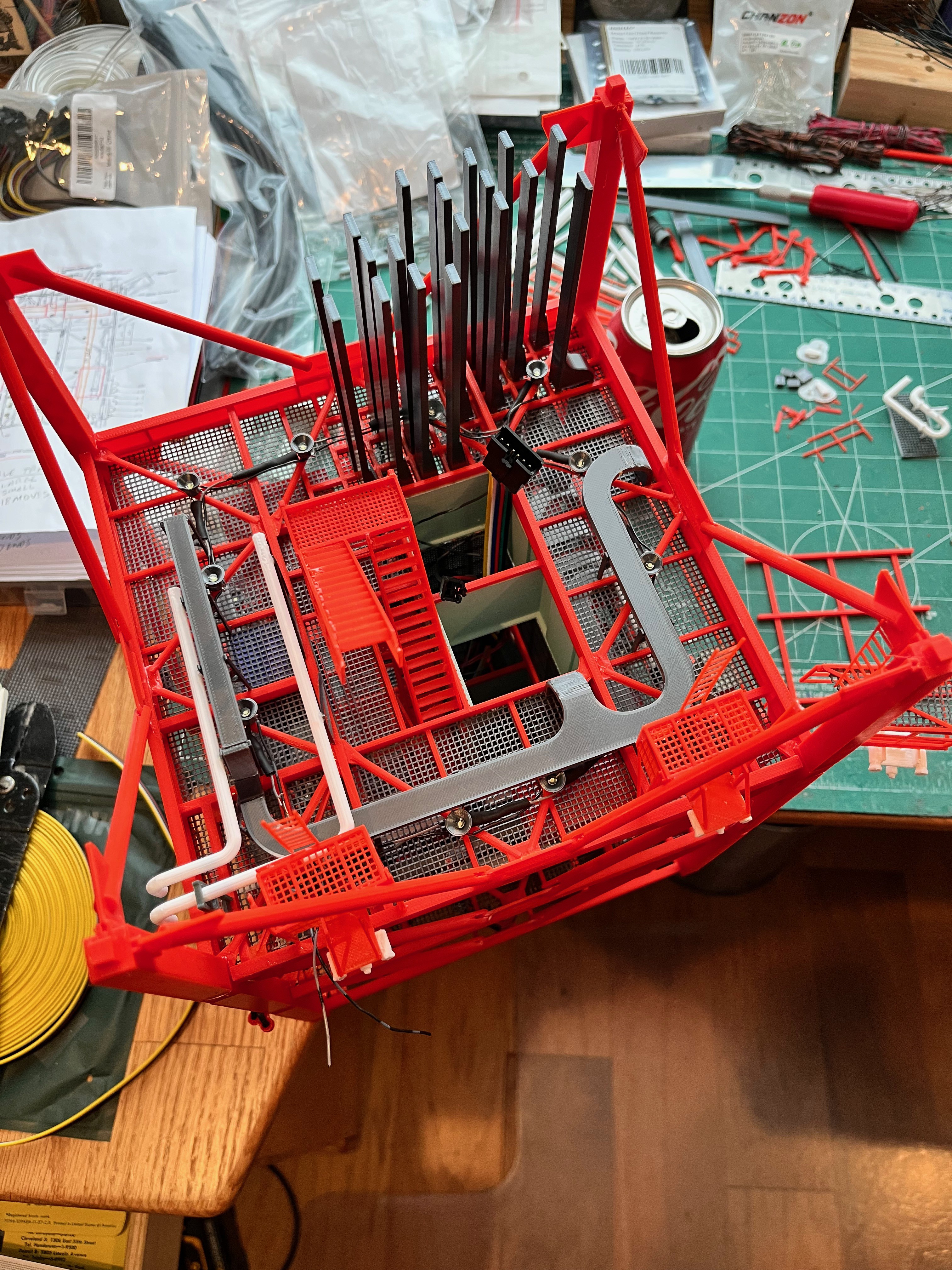
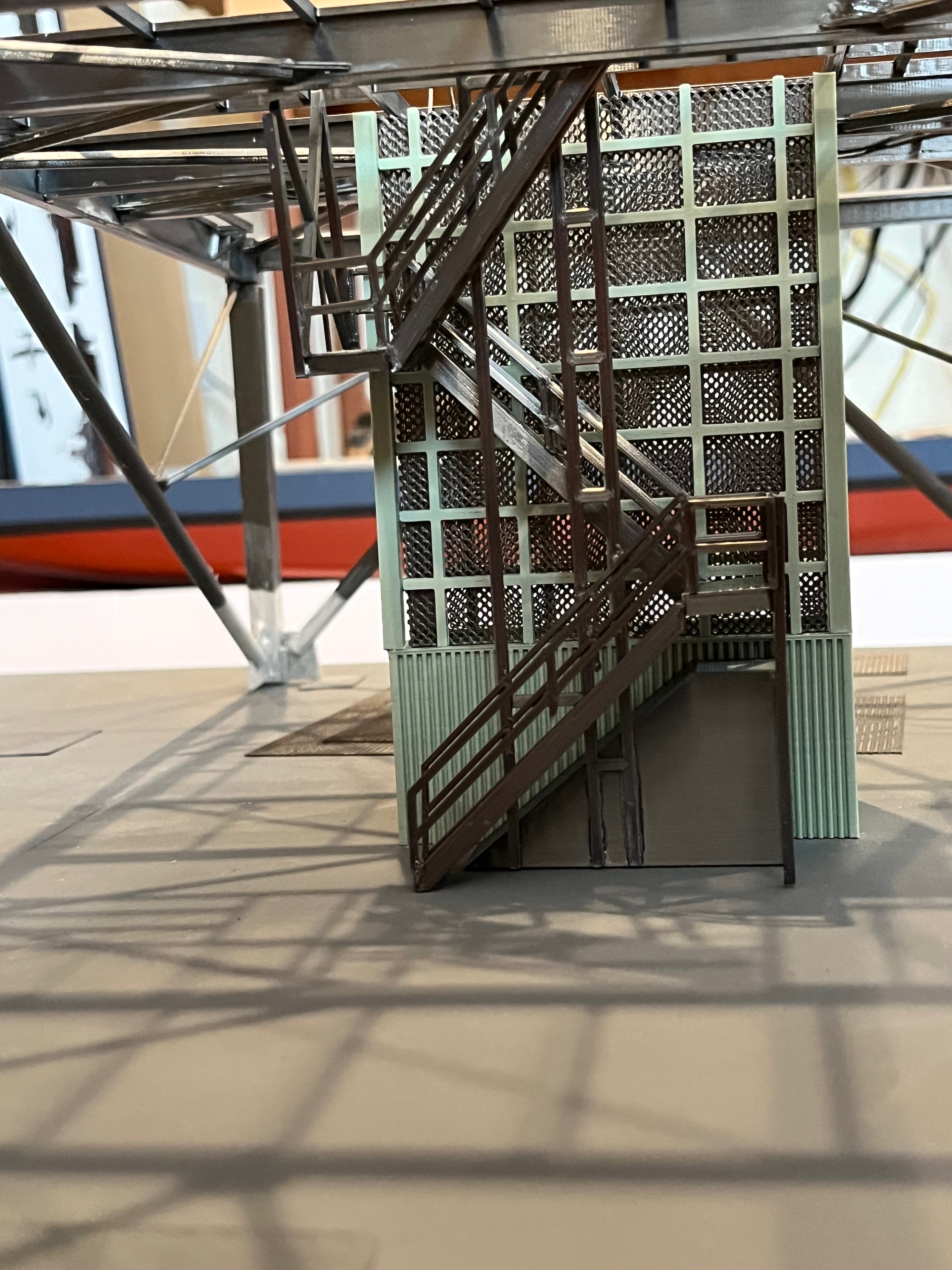
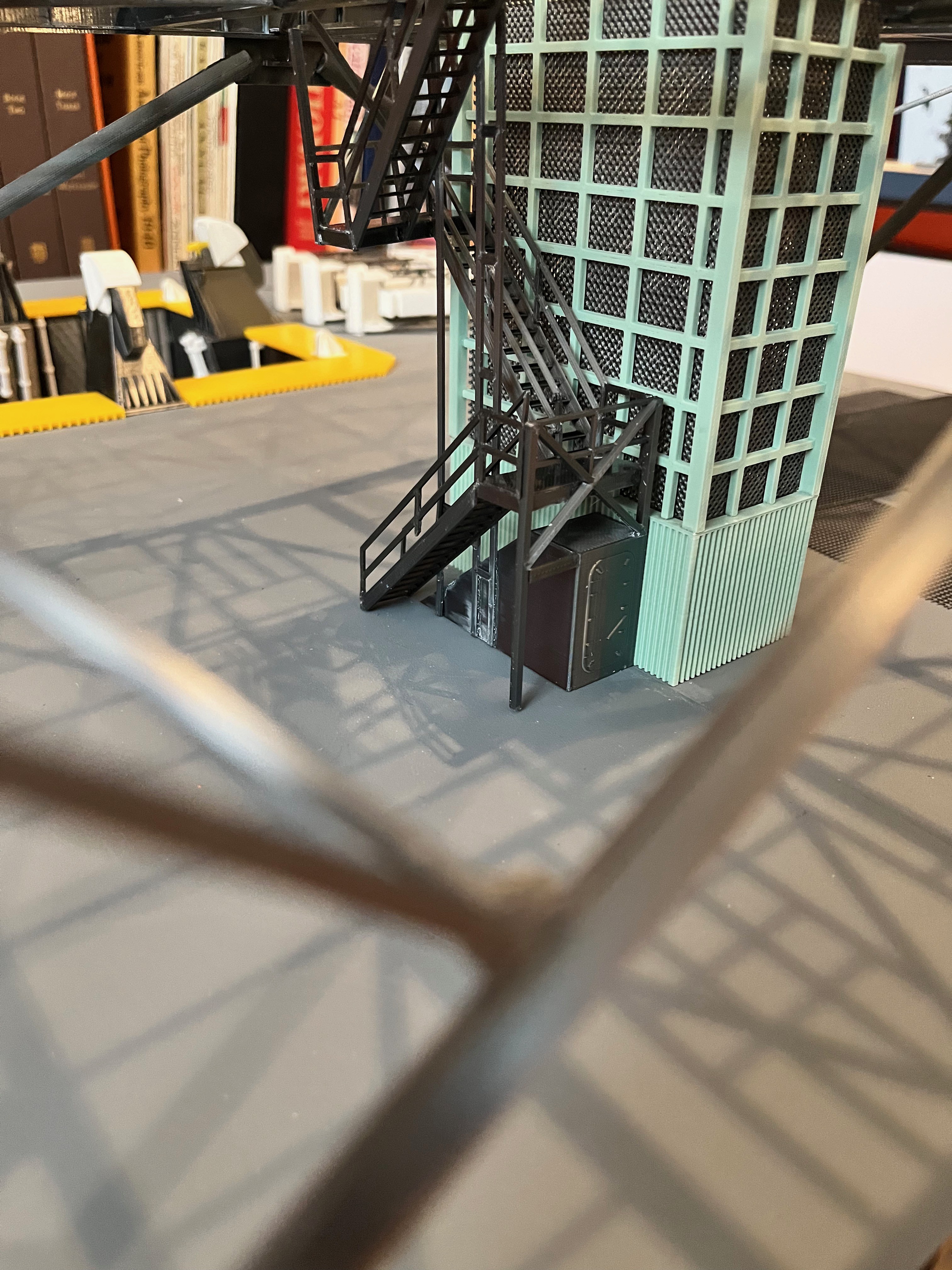
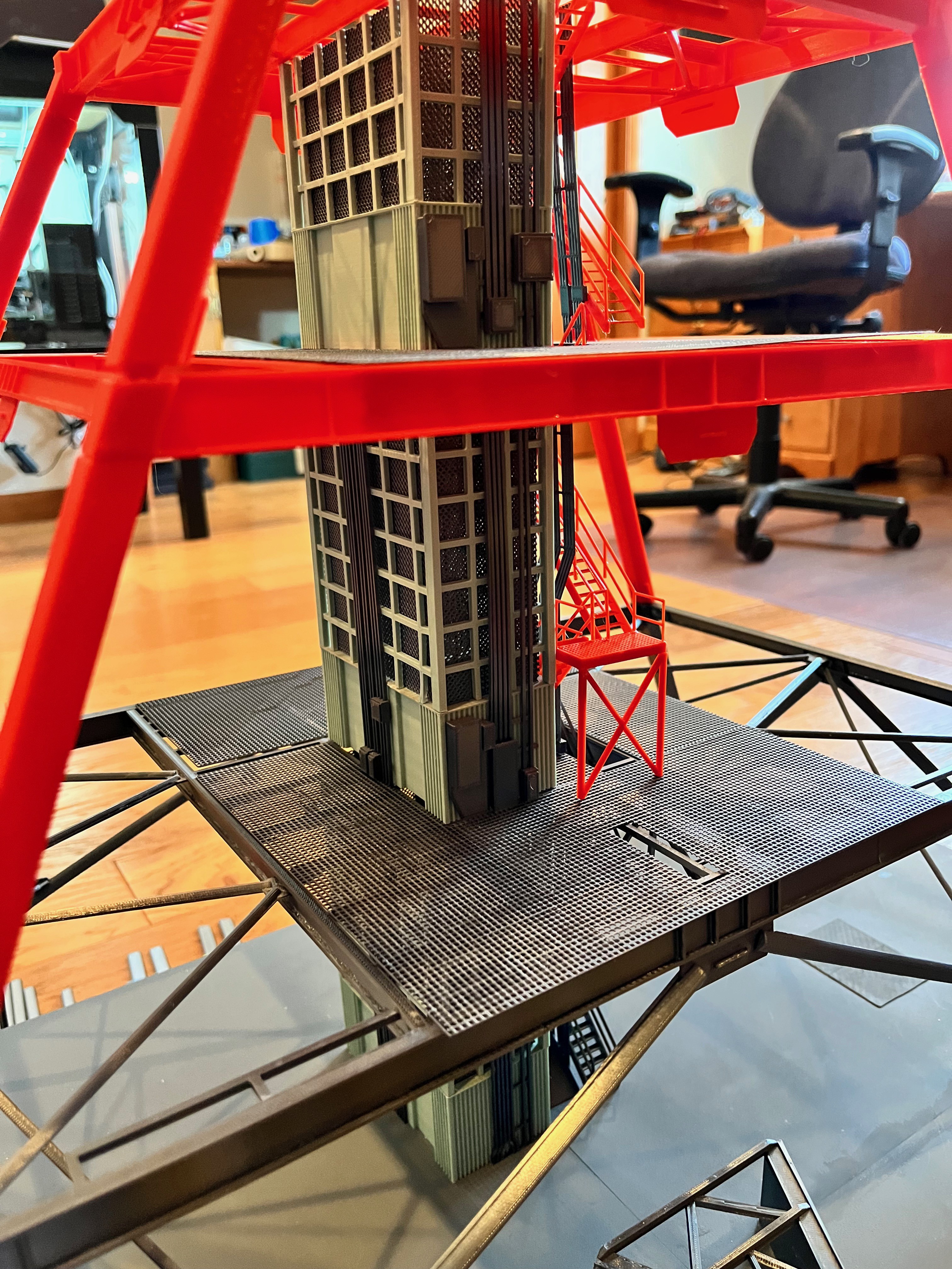
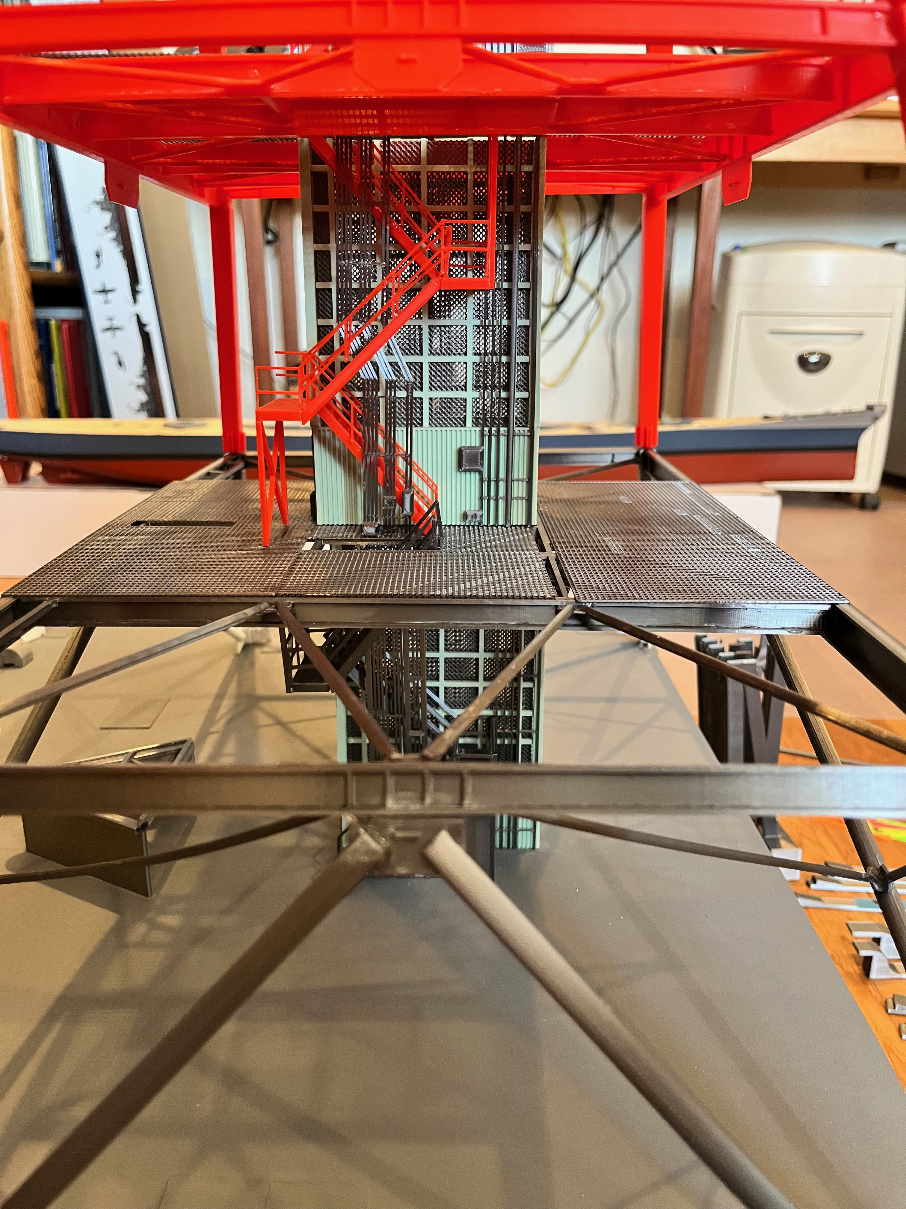
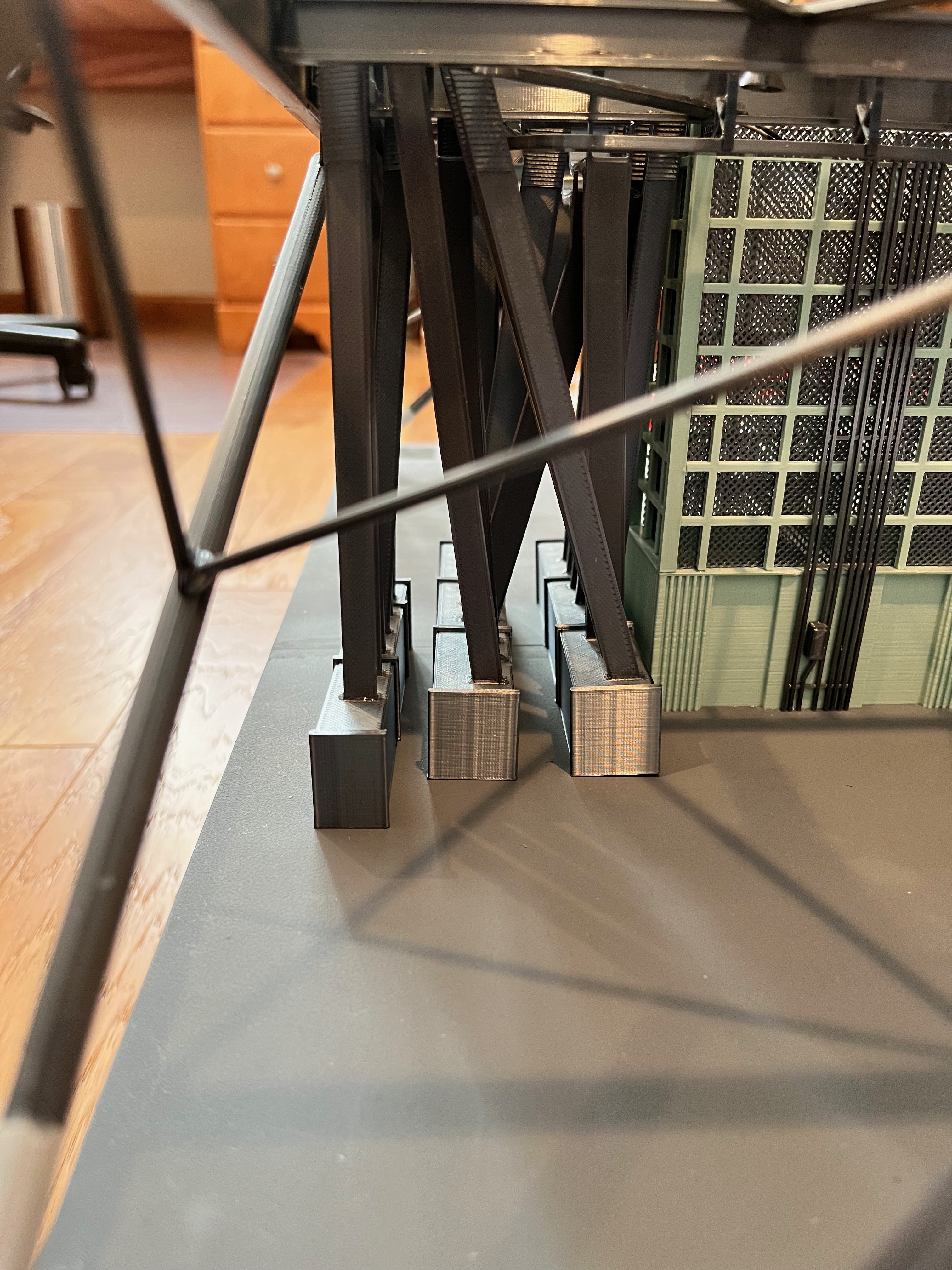
And here are more pictures of Section #3 upside down. You can see how the stairs and cable trays hang from the underside of the ceiling for these removable sections. The elevator is glued to the top of the previous section. The pipes for this level hang via some delicate brackets that are much easier to access while upside down, however I glued them on while the first floor of this section was in place so I could line up the pipes with the previous section.
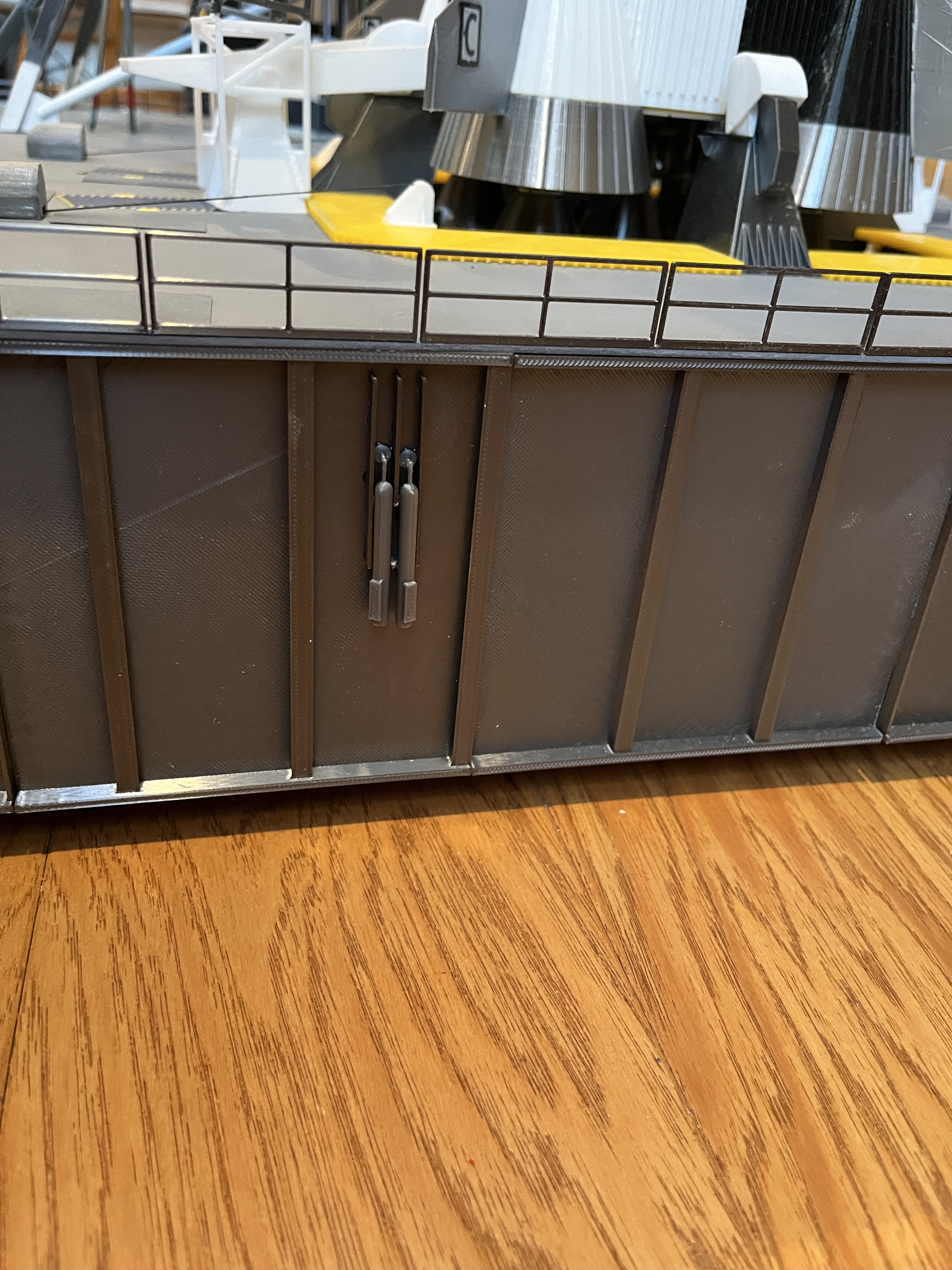
The original Aviator67 Side 2 Frame Cabinets had some seemingly extra boxes I wasn't using so I removed the lower boxes. The cabinets with attached cables look great! There are two types of cabinets. I have put these modified cabinets at L120 and L160. The spreadsheet of parts has been updated, hopefully correctly and the two new parts have been added to Printables.
Section 3, Side 2 pipes complete. I feel like I am reaching Max-Q, the progress is slow but as the pipes end I realize the higher you go, the less parts there will be per floor so I should start gaining speed.
Here is the equipment glued to the L180 floor. I still have to add the lower part of L190.
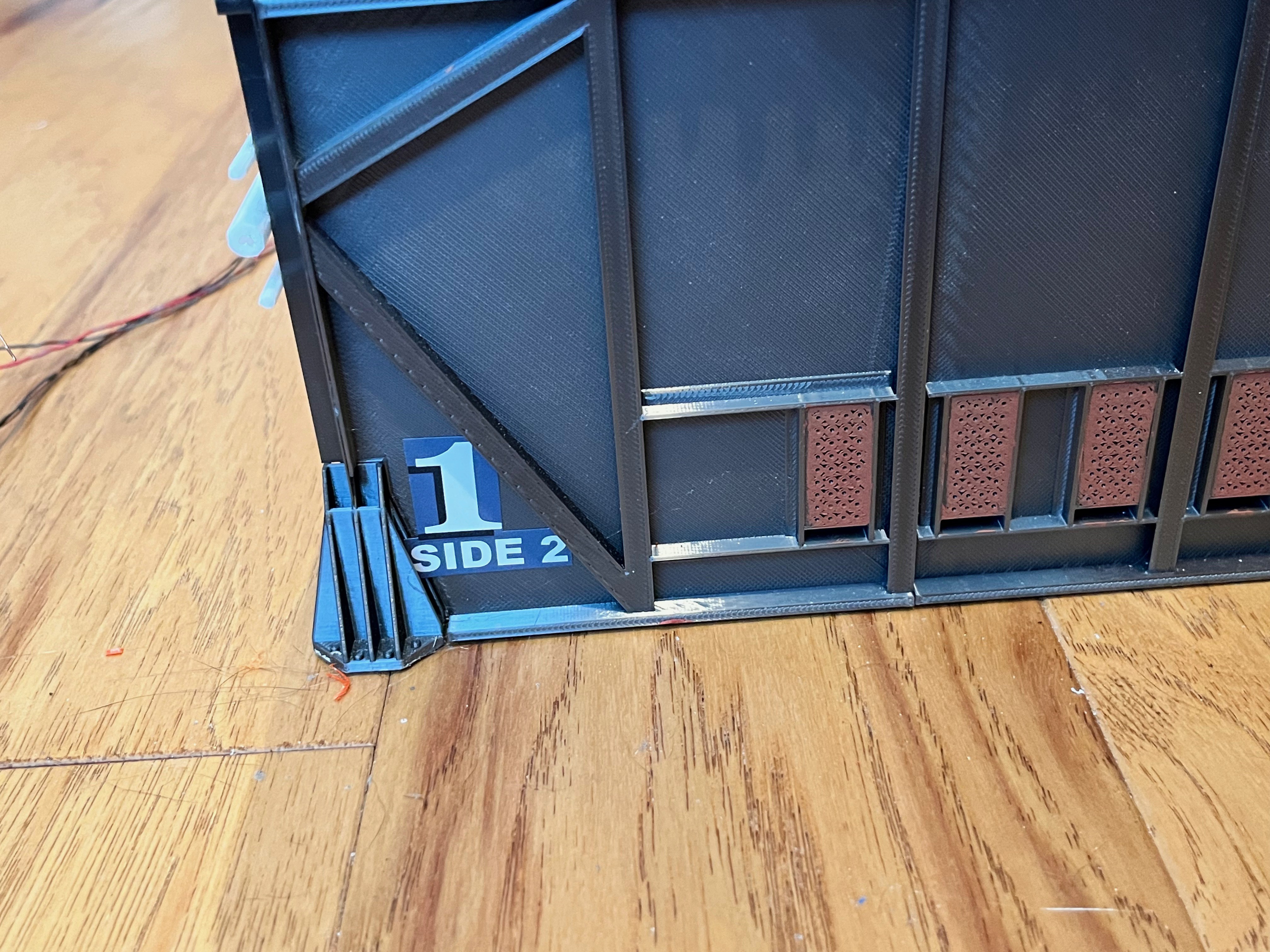
Section 3 Side 4 pipes complete. At each level there are three small vertical I-beams. I did not create these, but copied them from the Aviator67 support structure on Side 2. These are not the way I usually split I-beams where the seam is visible, but it saves me some work and two of the parts are hardy visible. There are also three stand-offs per level. The lower one can simply be glued on. The other two wrap around the floor cross brace. For these I use a sprue cutter to nip away at the backside to get them to fit around the brace. Many of these parts require a little fitting on your part. These stand-offs should line up with the hydraulic pipes. Your fitment may vary.
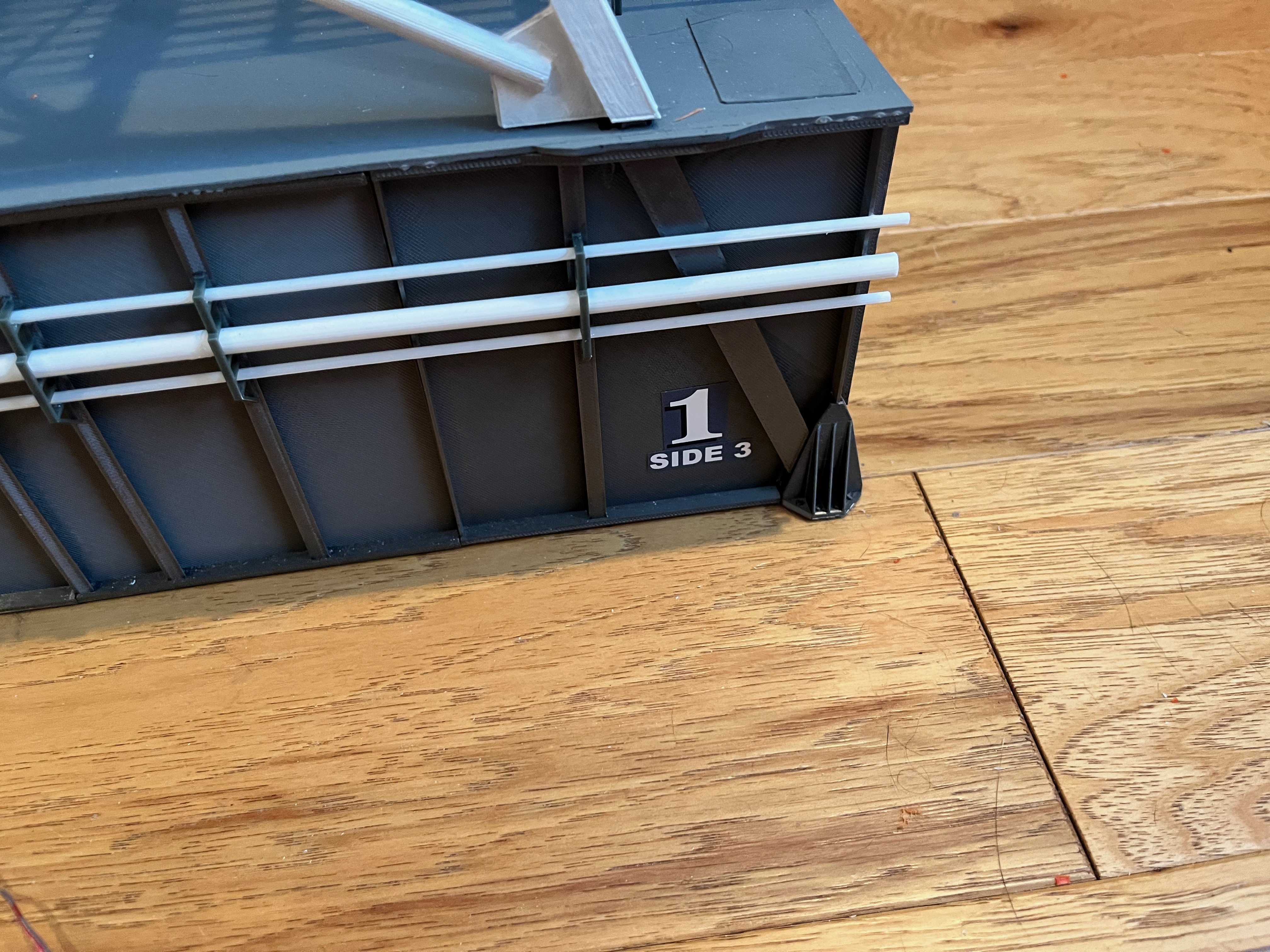
Section 3 Side 3 pipes are complete. Another pipe ends and two taper down. Notice that there is an interesting pipe support for the LOX pipes.
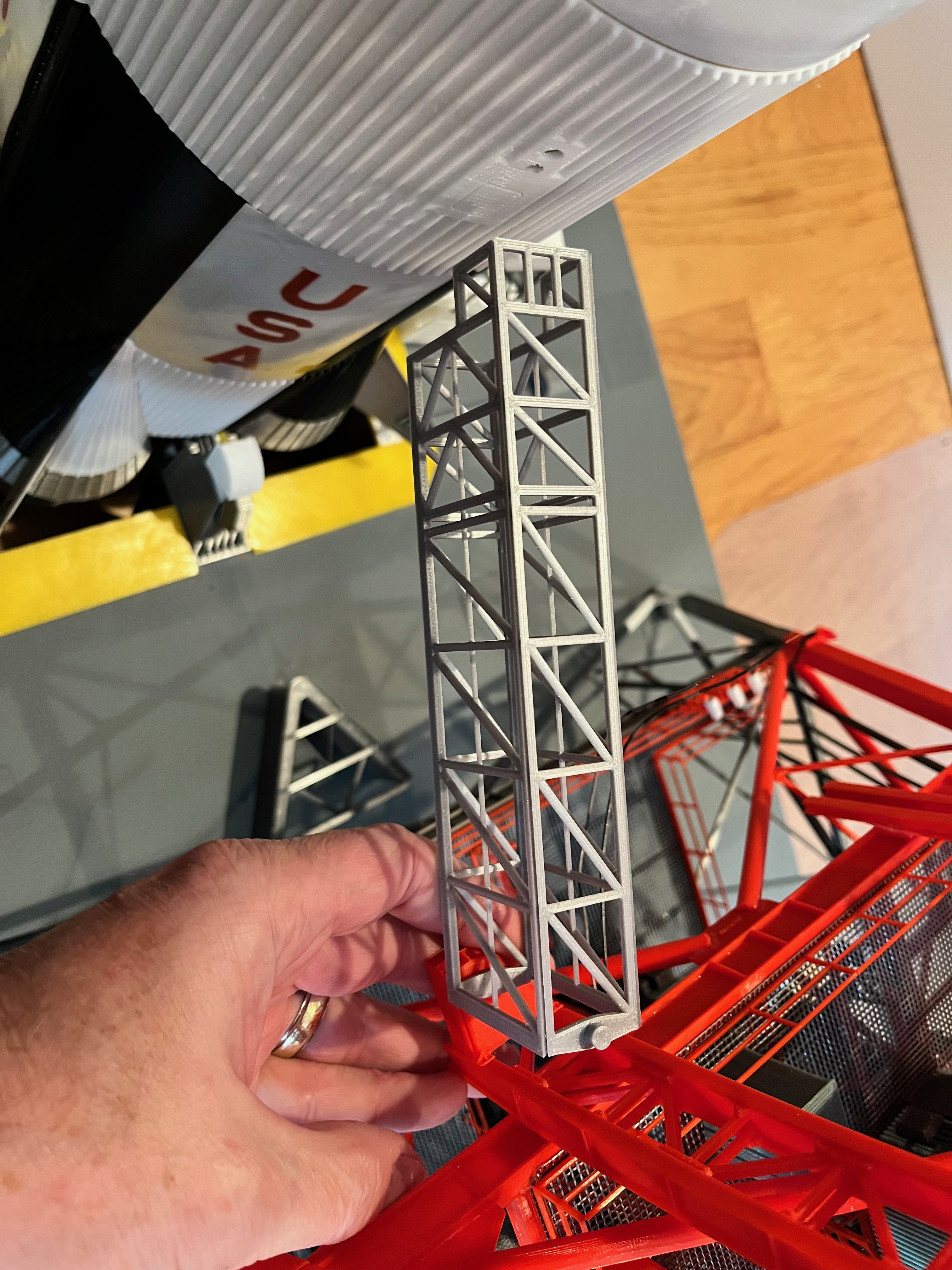
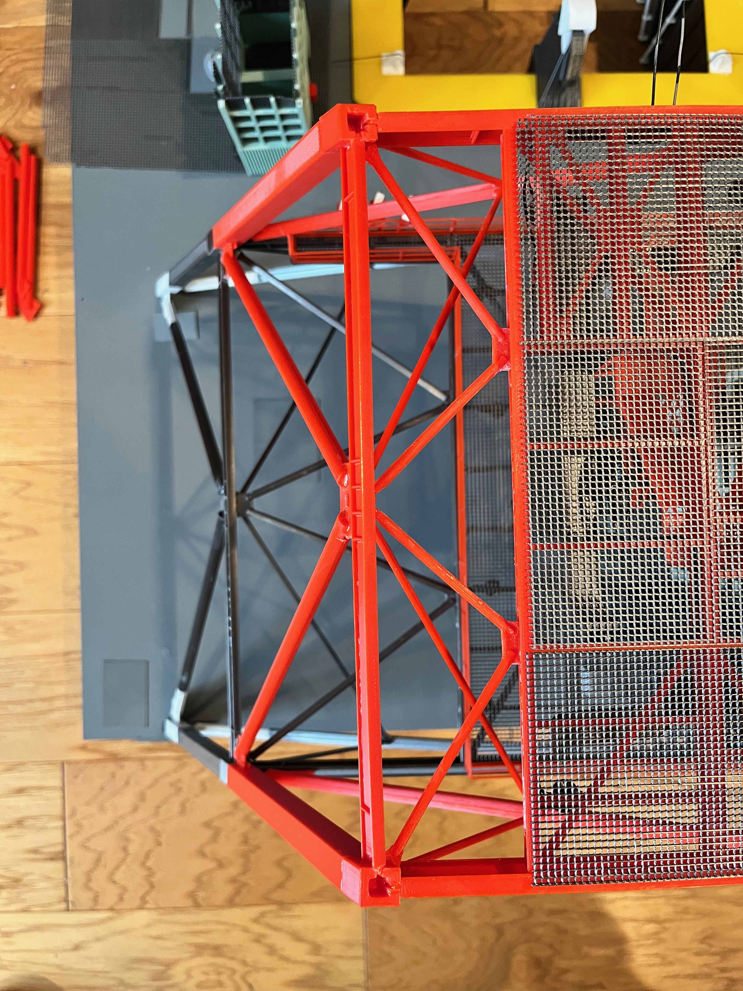
Section #3 Side 1 support and locking columns are on. I even added the camera on a pole at level 160. That makes 16 cameras so far. Why a camera on a pole? Because apparently you can't have enough cameras.
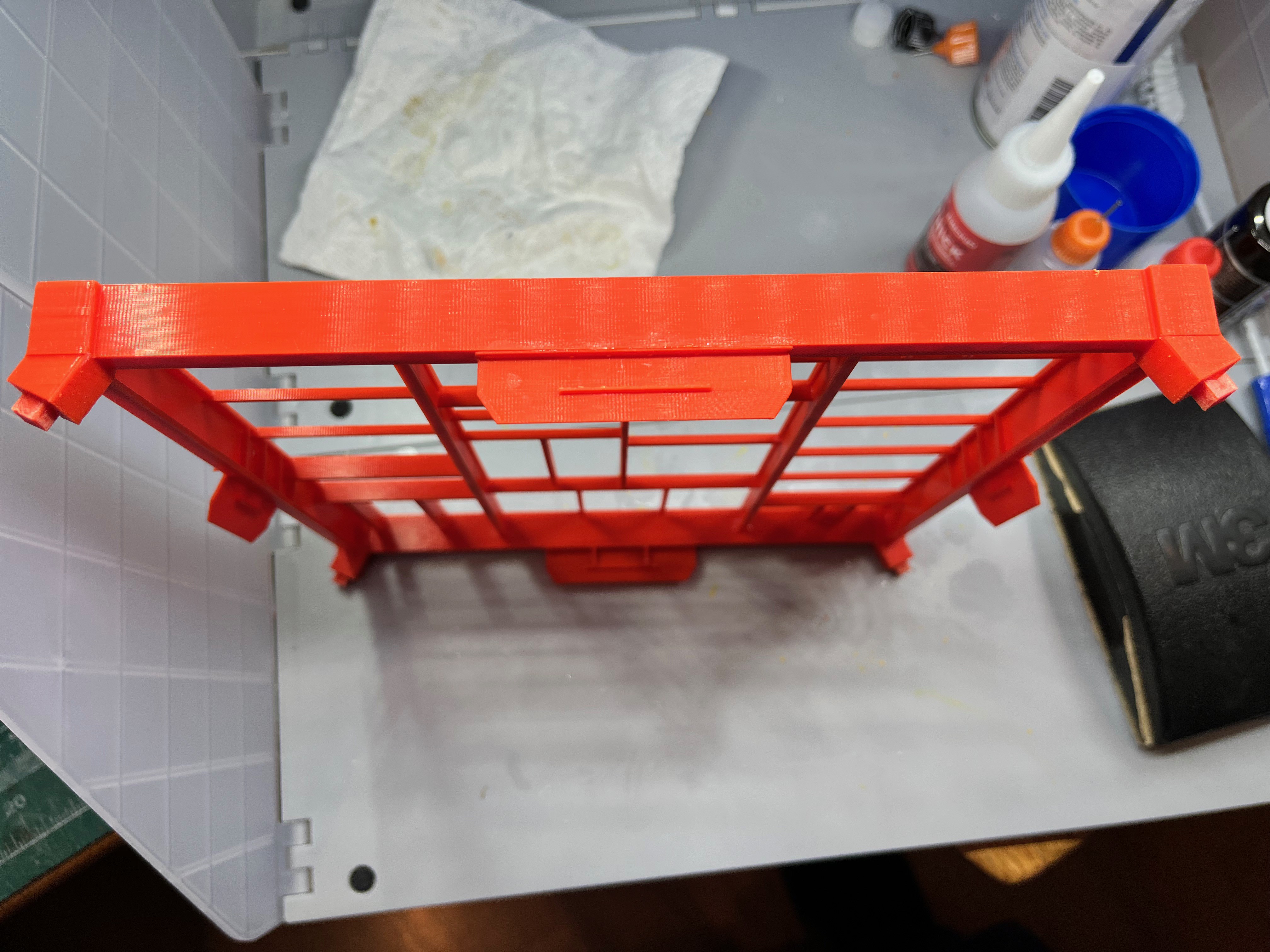
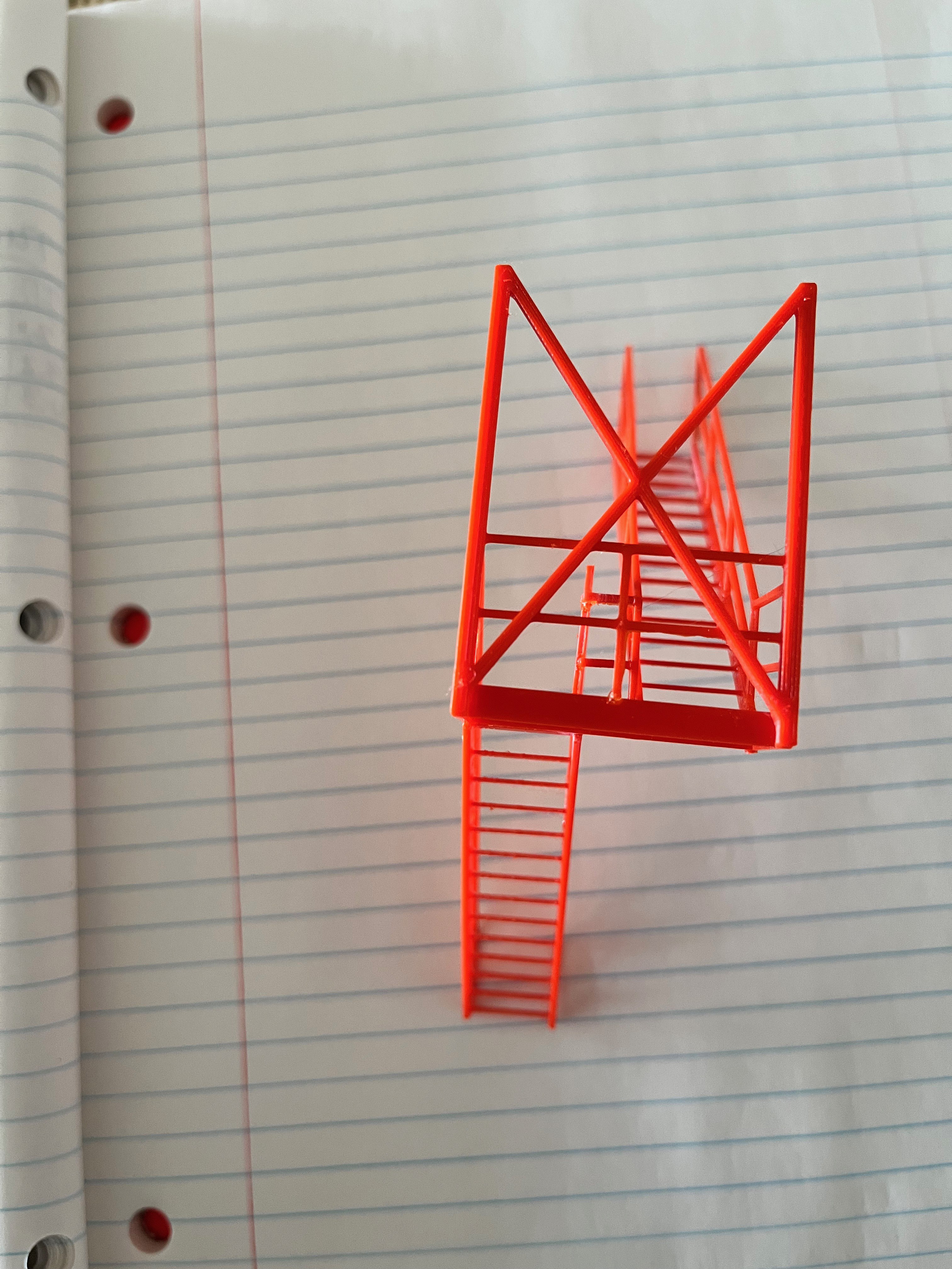
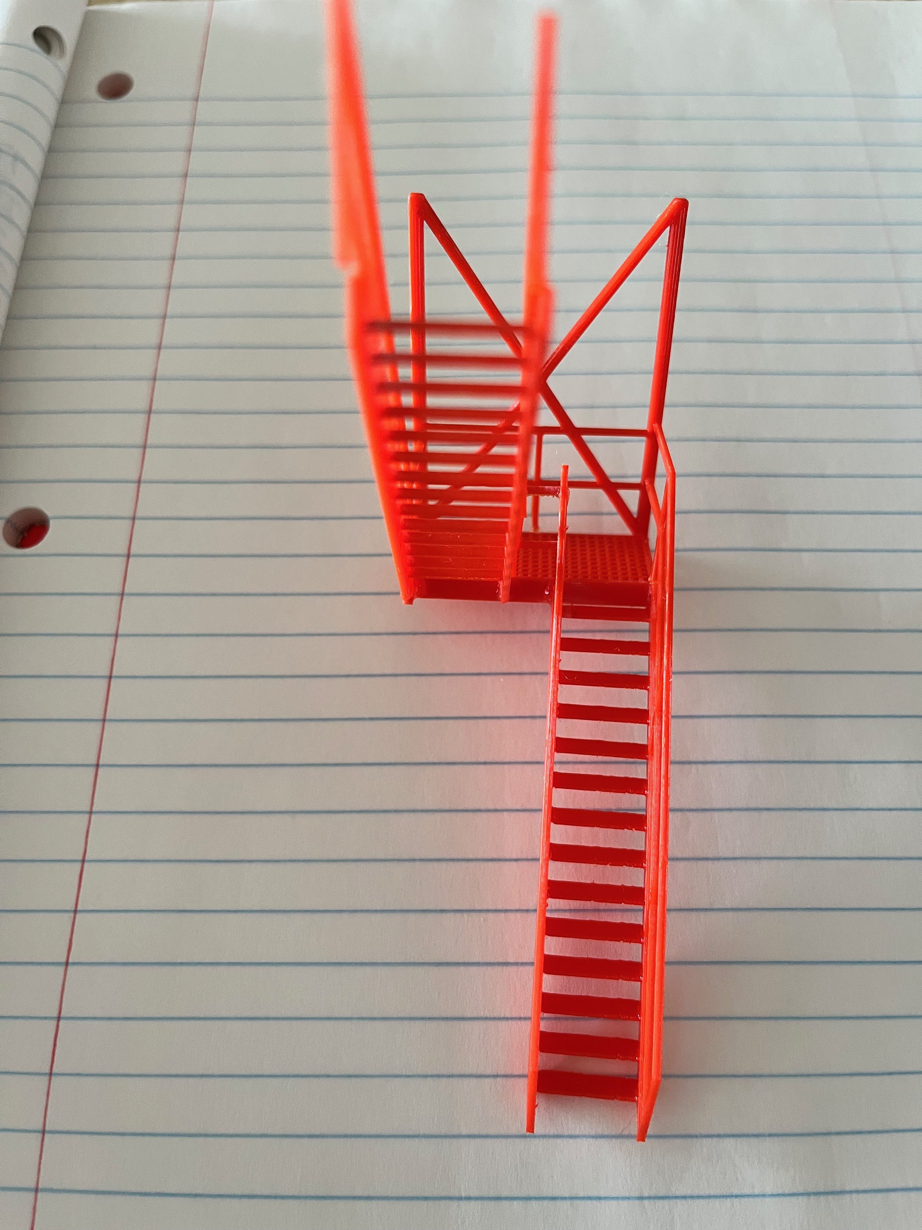
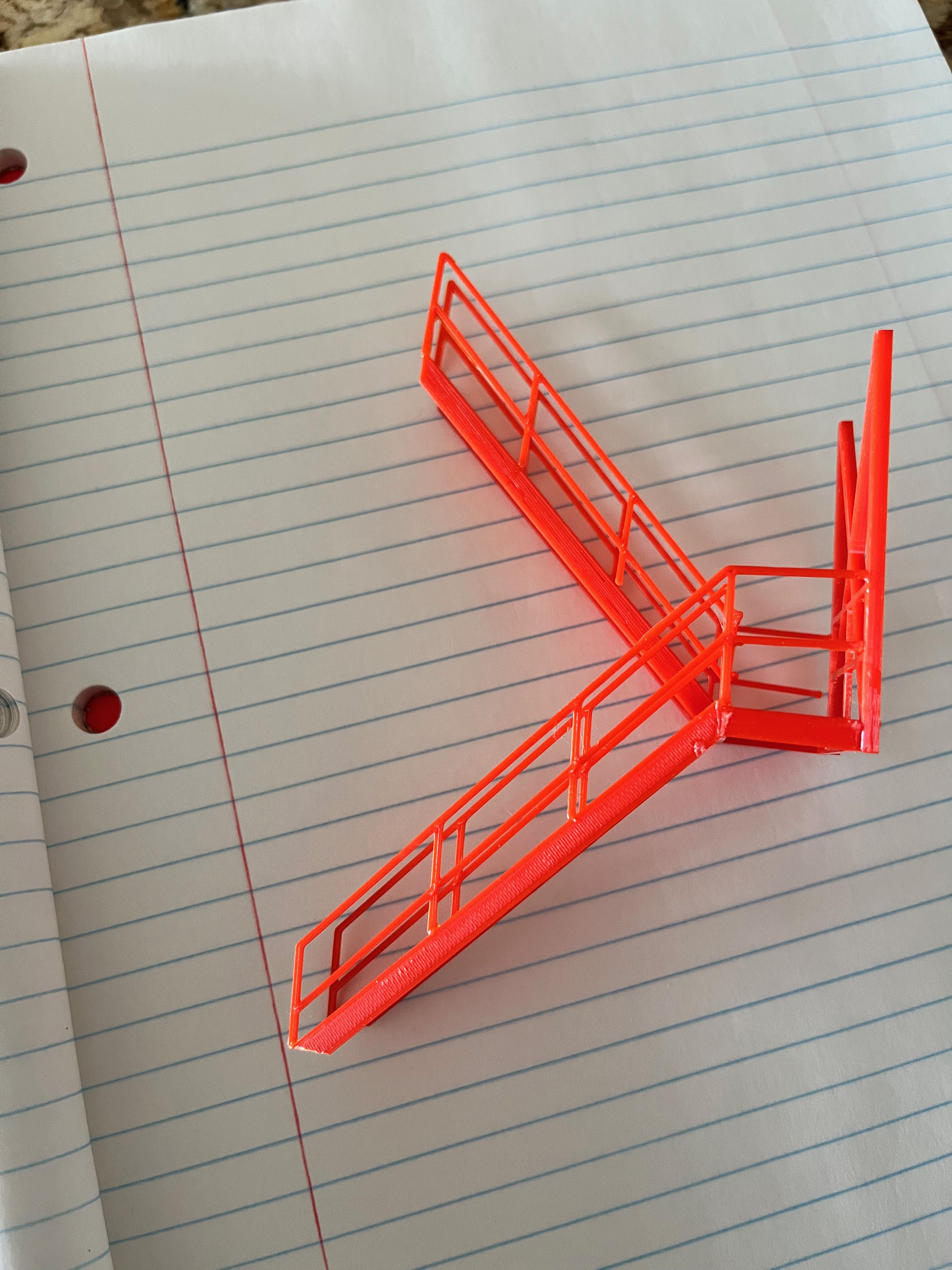
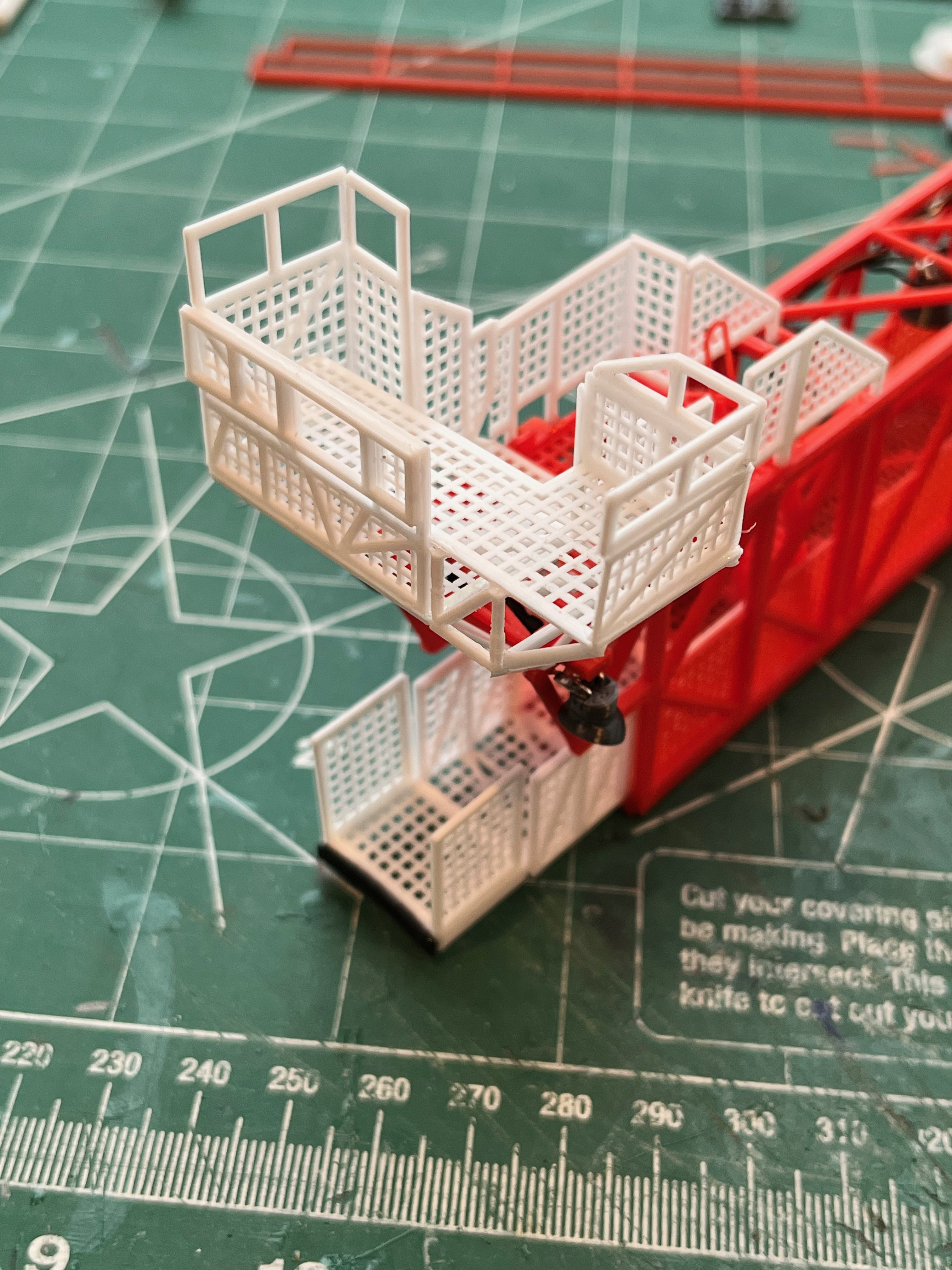
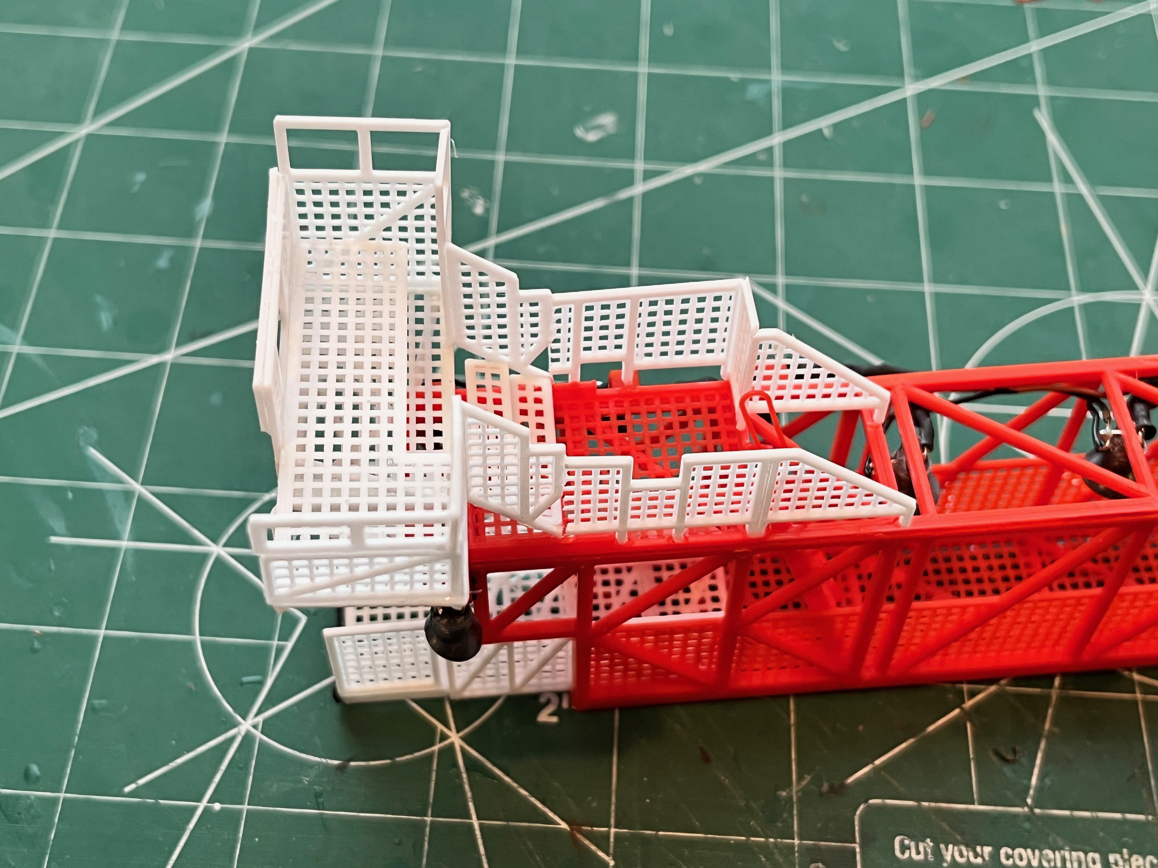
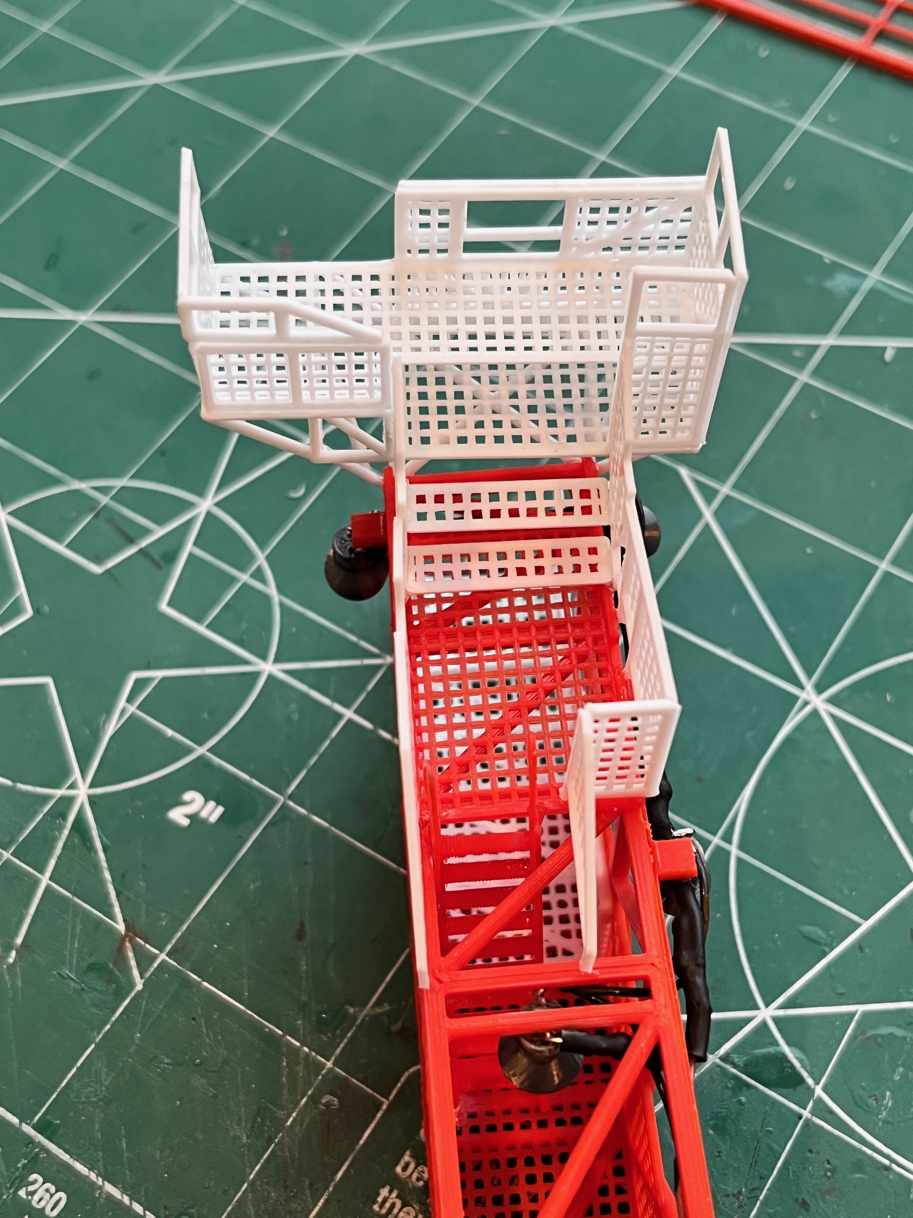
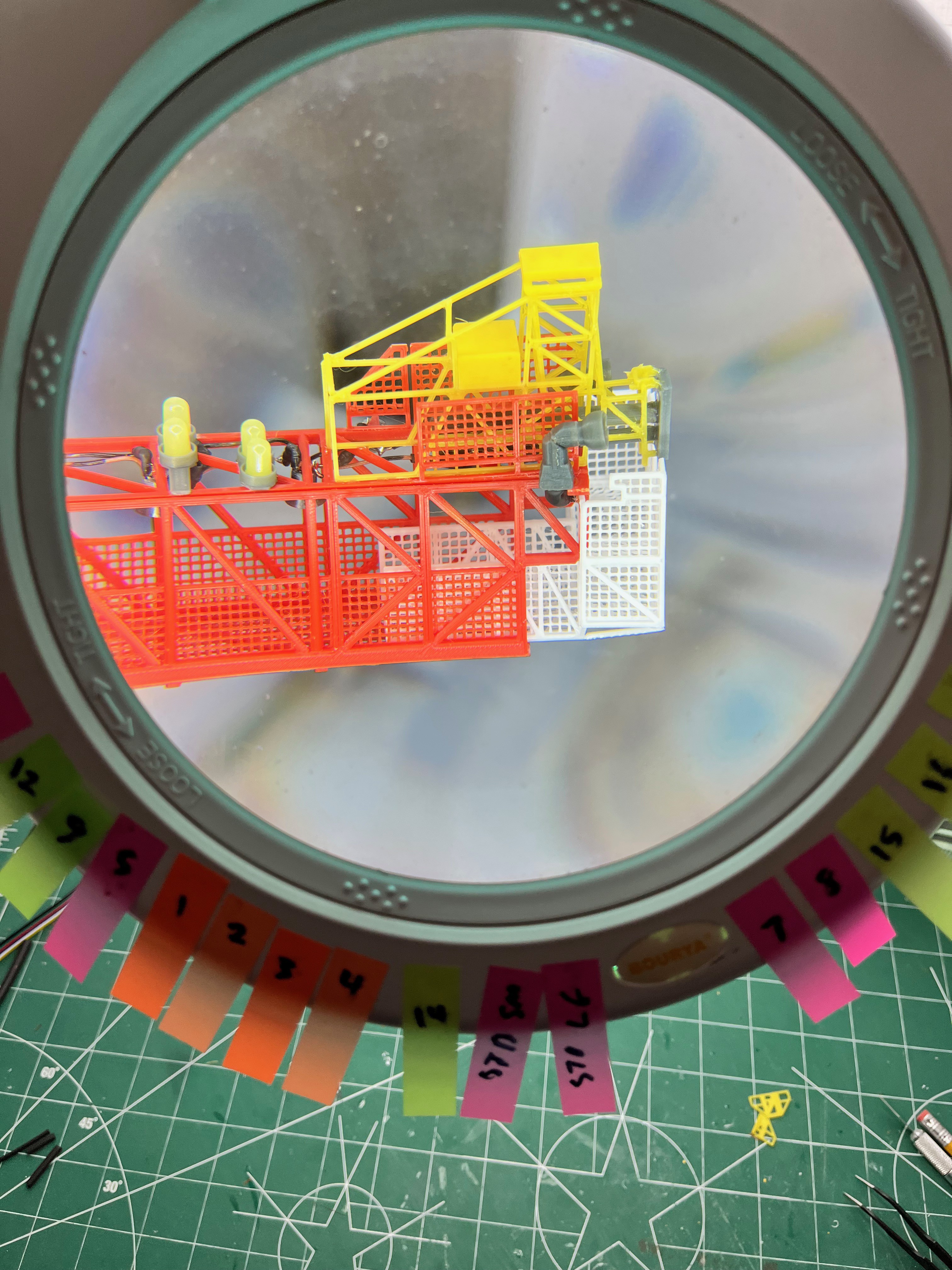
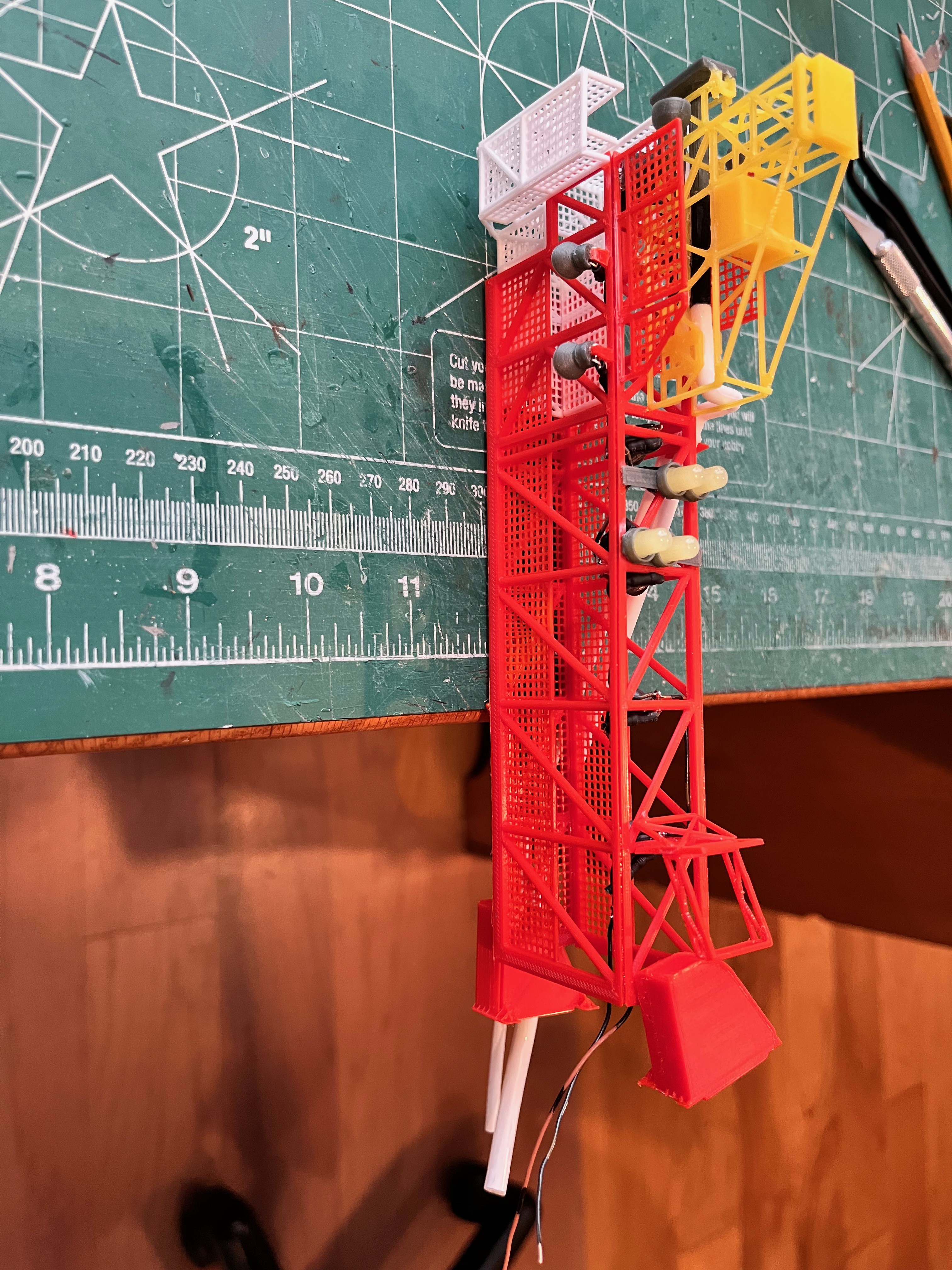
Swing Arm #3 is built and ready to attach. I'm happy with the way the end platform went together. There are many ways to configure the walls of the upper platform as the upper wall parts can be folded down (I only folded down the front portion) and the walls can even be laid flat. This arm was easy because there are no pipes. I did have to trim the lower side panels just a little to get the length correct. You can see this in the side/top perspective picture. I glued those side panels on then glued up the rest of the upper platform as a separate unit and then with the arm in place positioned the upper platform to decide how much to trim.
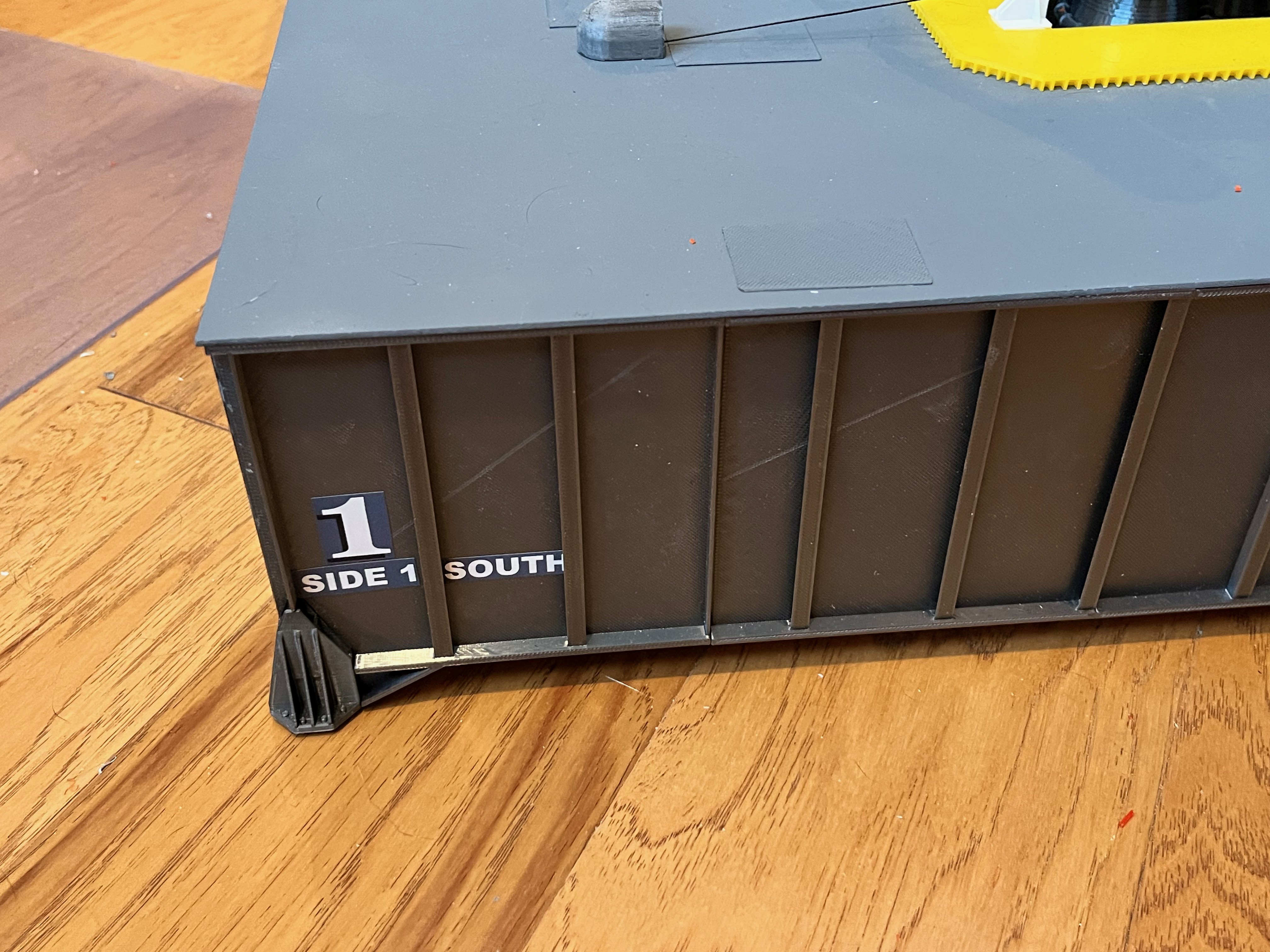
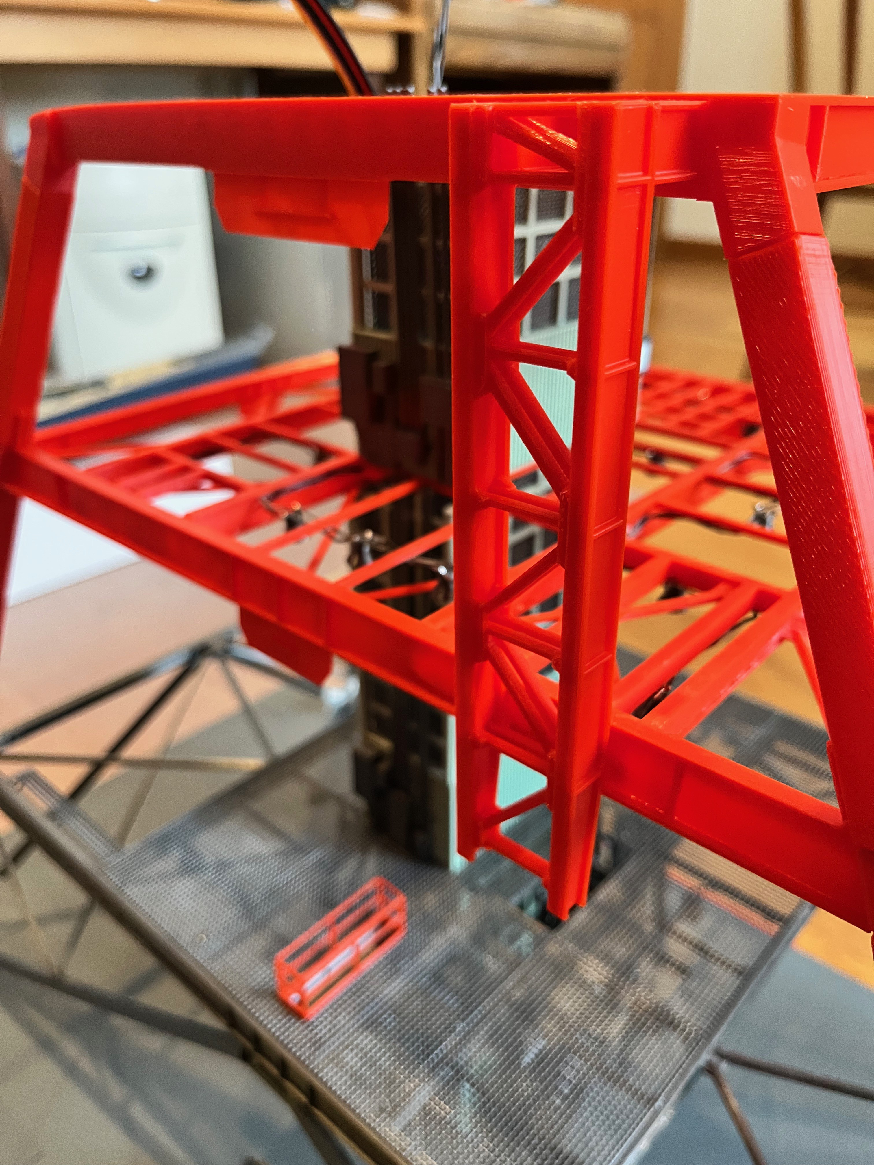
The one issue that is not really an issue is the position of the lower hinge for this swing arm. The removable sections of the tower alternate between two and three floors. The support columns however have a length of 2.5 floors. This is so that these parts are all the same length and they just fit on the print platform diagonally. This means that the second removable section has a support column that sticks up half a floor level (10 feet) above the top floor. This allows swing arm #2 to be fully attached to the second section. It turns out swing arm #3 spans sections 2 and 3. The lower hinge just fits onto the support column for section 2 (see picture below). The upper hinge will glue to the support column above (the one attached to the third section). This is OK because if I ever disassemble the tower, the swing arms will first be swung against the tower and tied in place with string or twisty ties. Swing arm #3 will also need to be tied at the hinges to the third section. Once removed this arm will only be attached to the upper hinge.
Swing Arm #3 complete! By far the easiest of the swing arms. The files for this arm have been published. I still need to add the camera to the walkway.
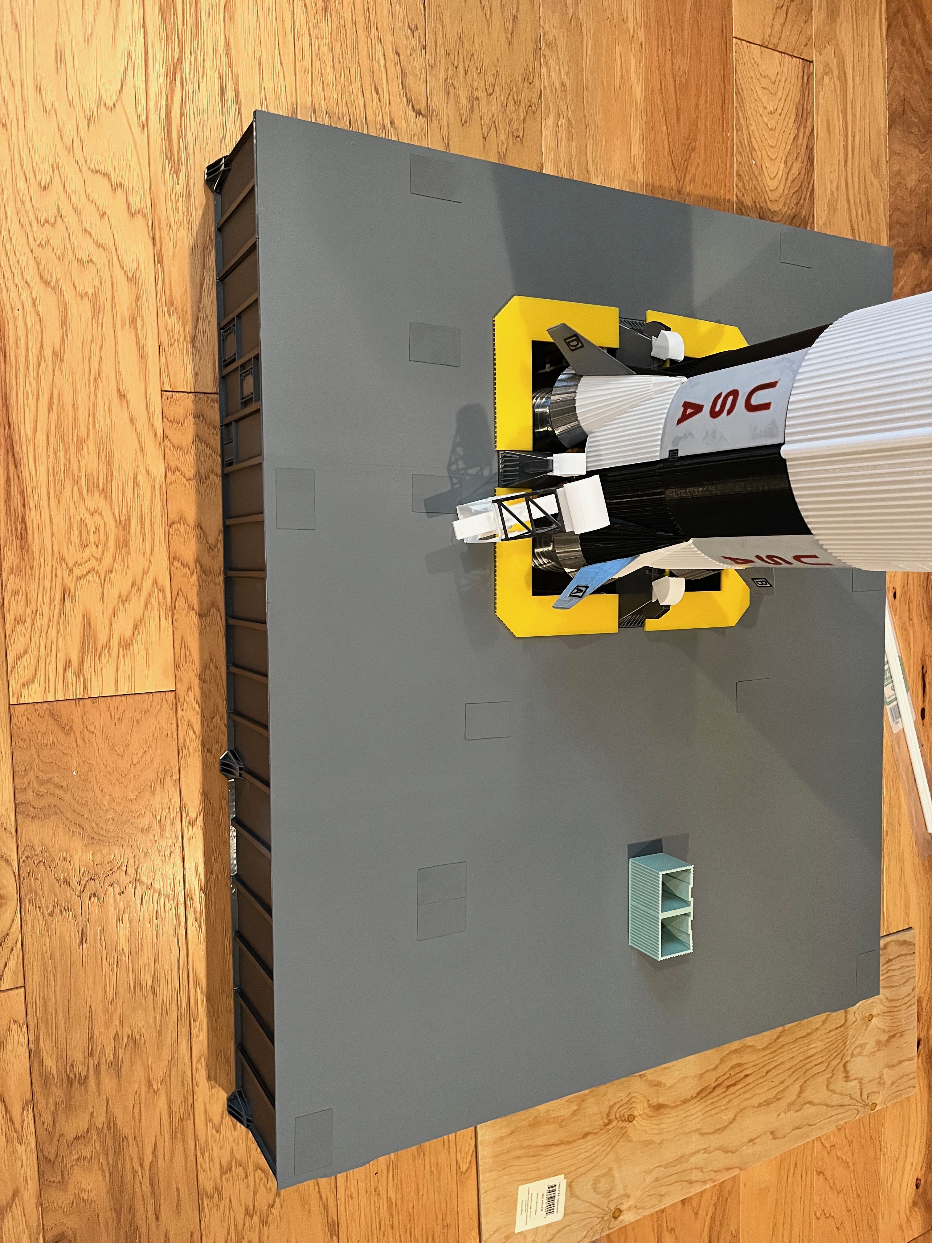
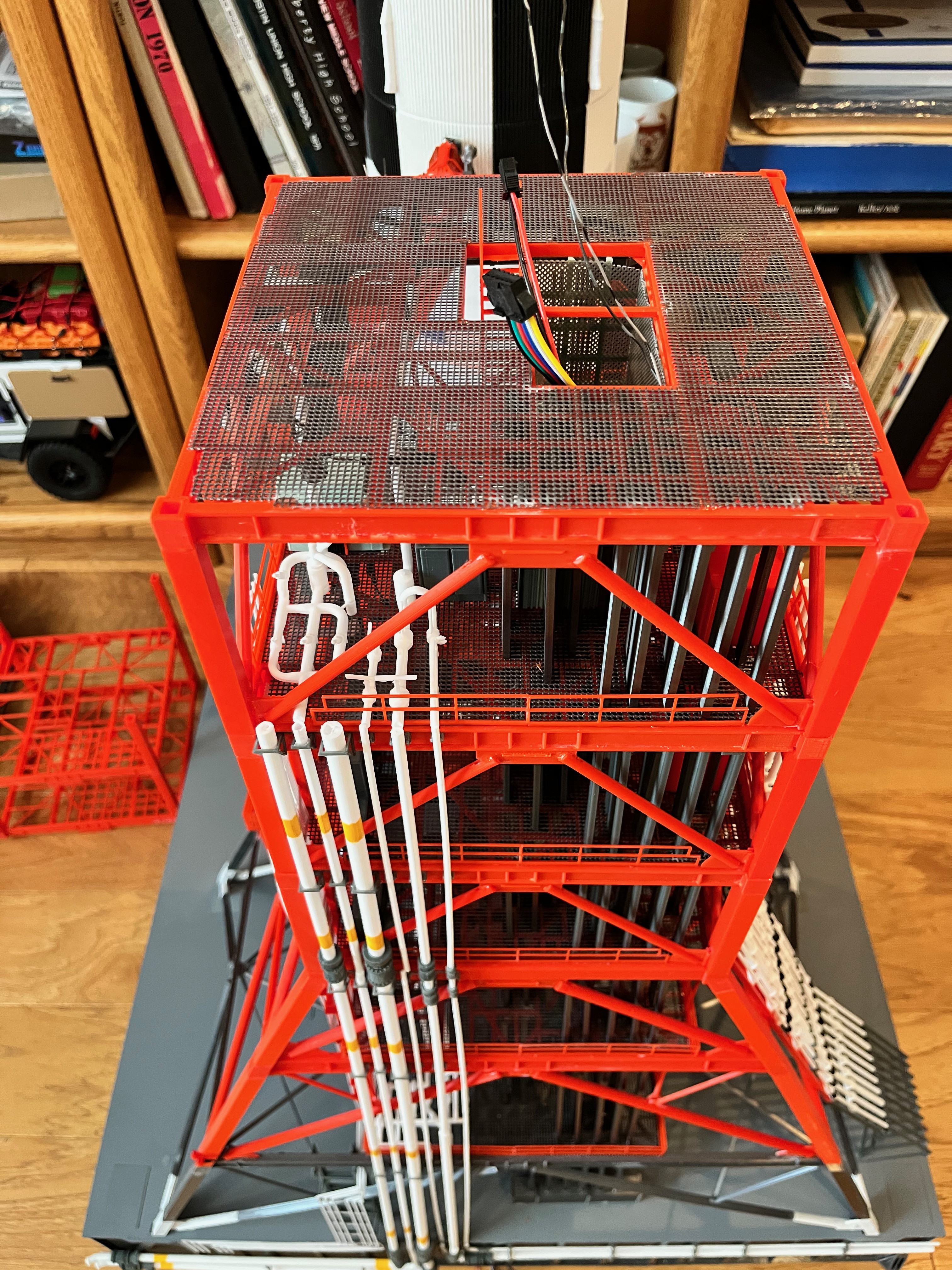
Level 190 is split into the lower section that is glued to the L180 floor as shown in the picture below. The L190 upper section will be glued to the ceiling of L200.
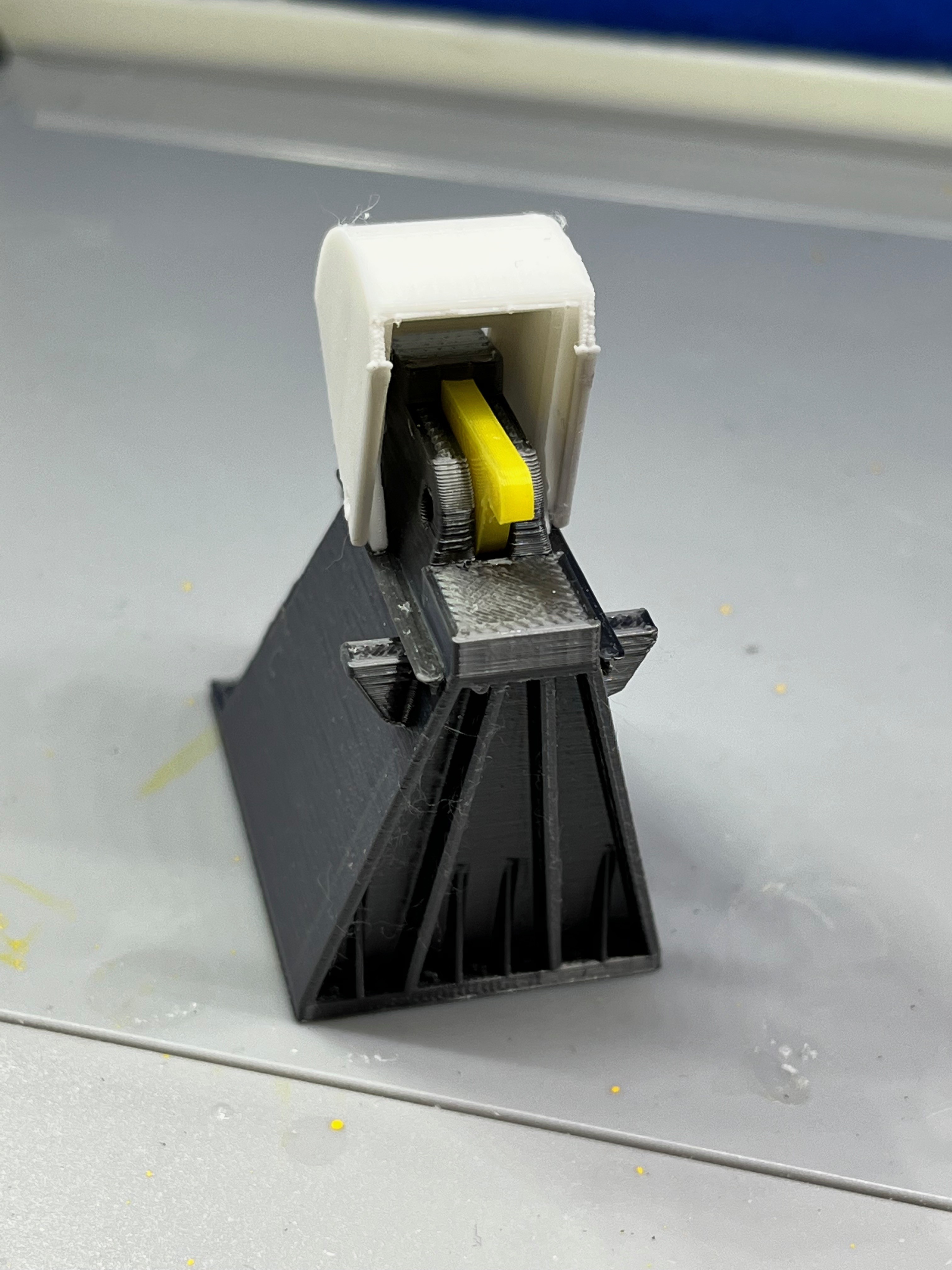
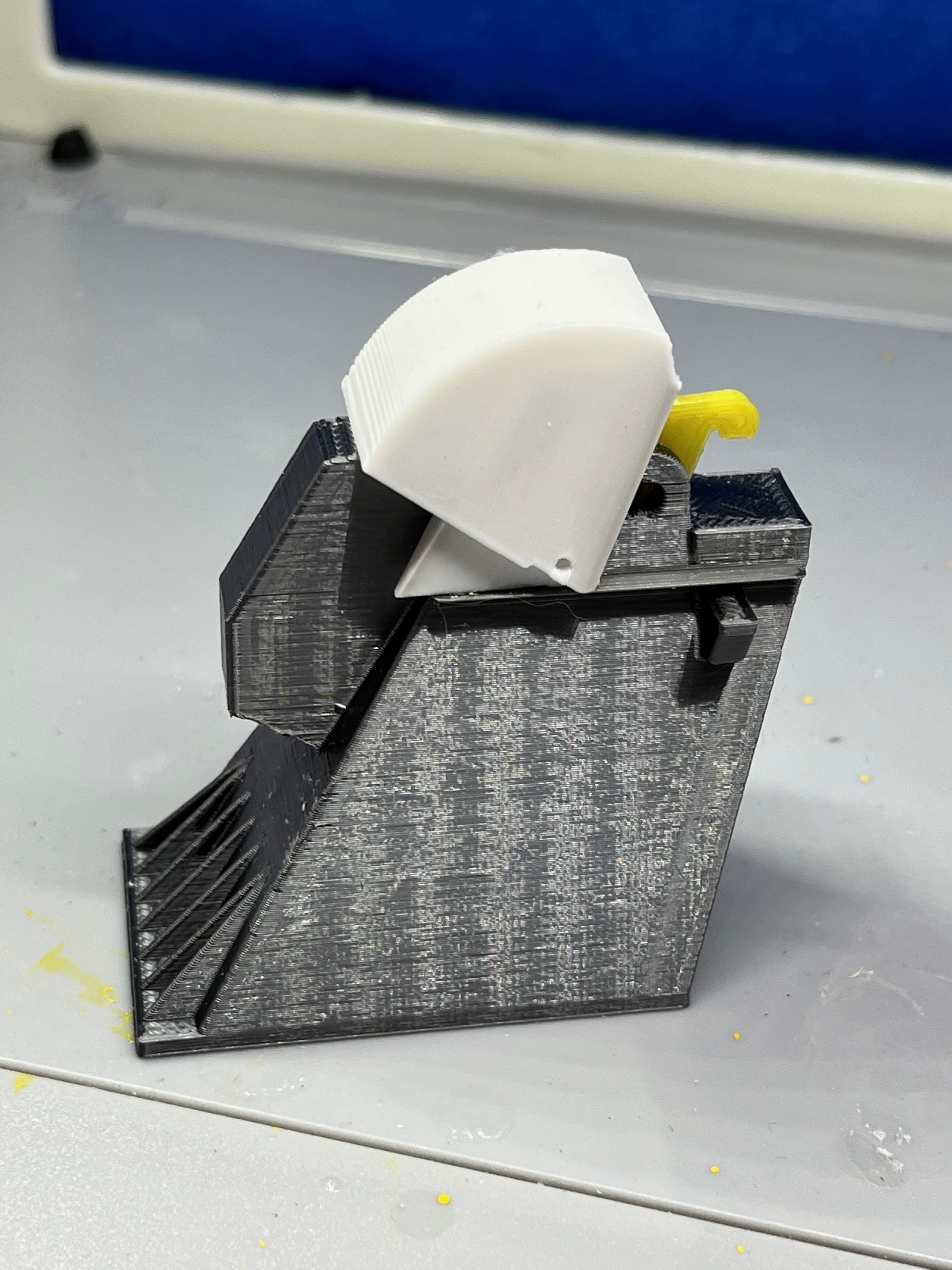
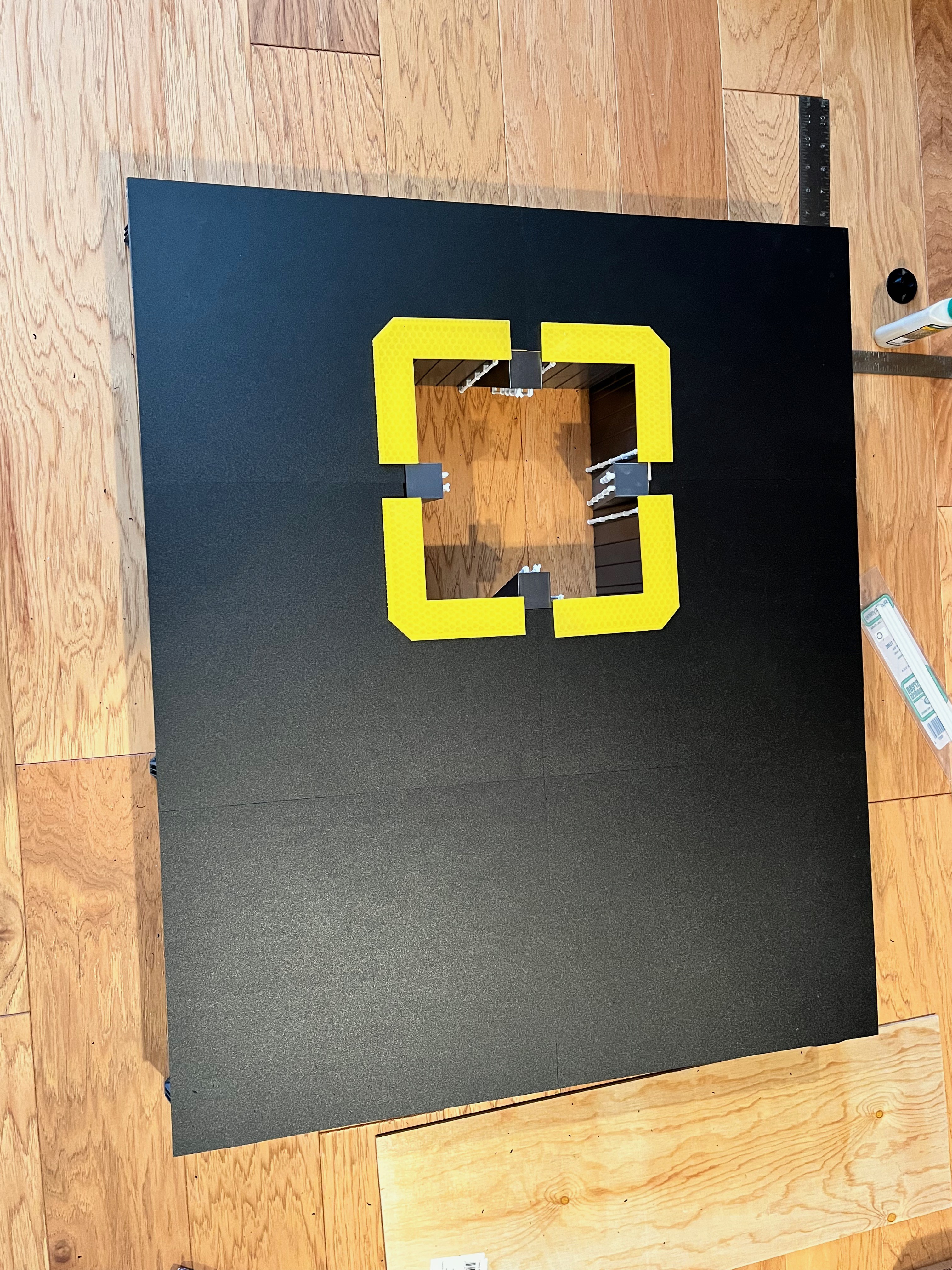
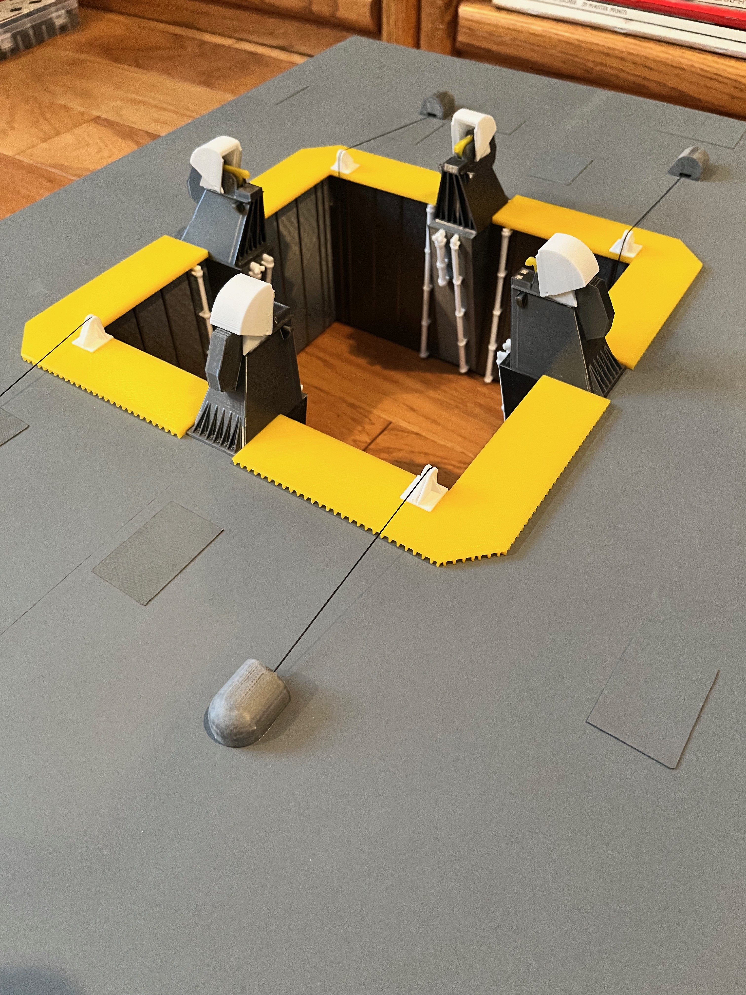
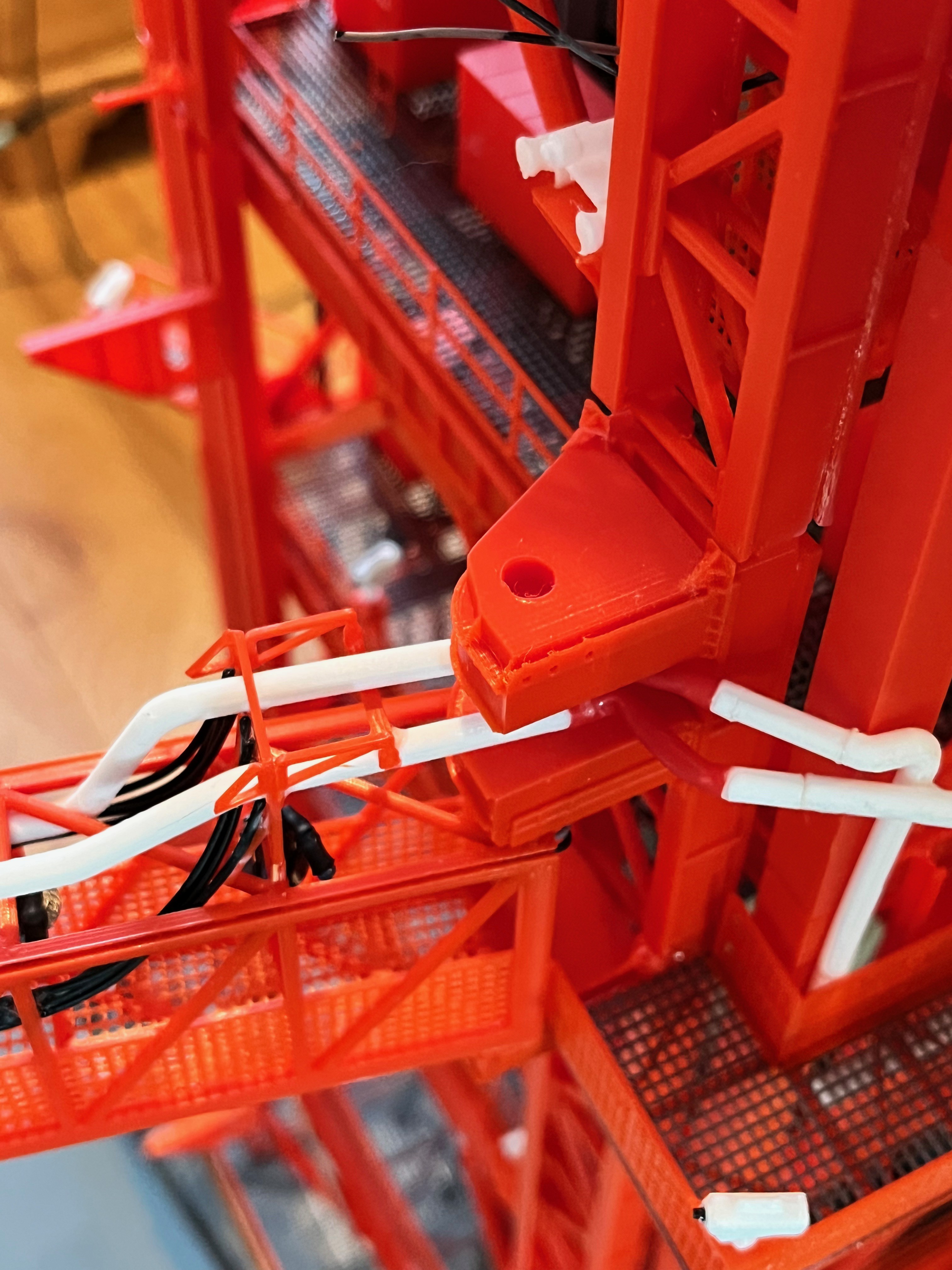
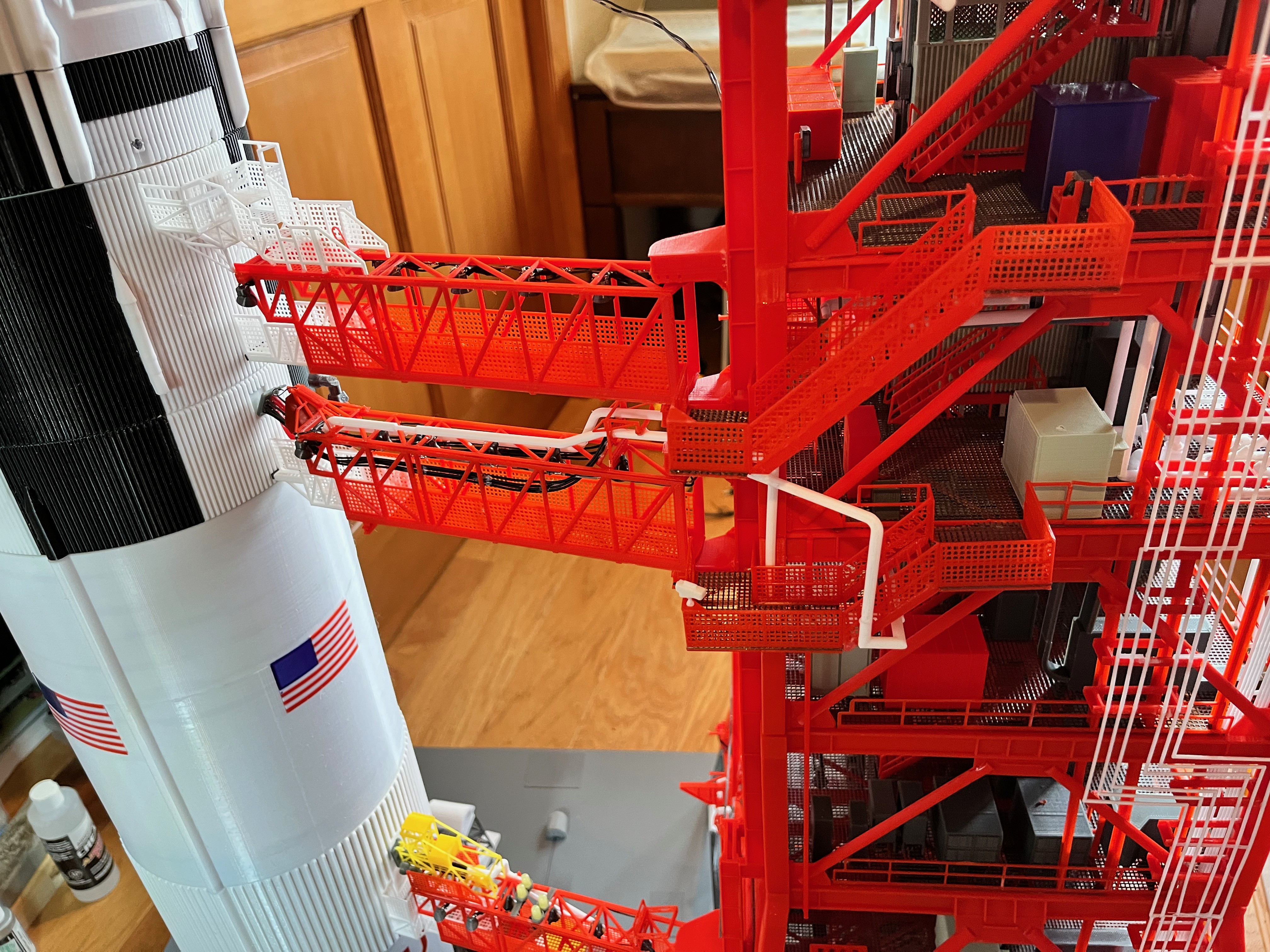
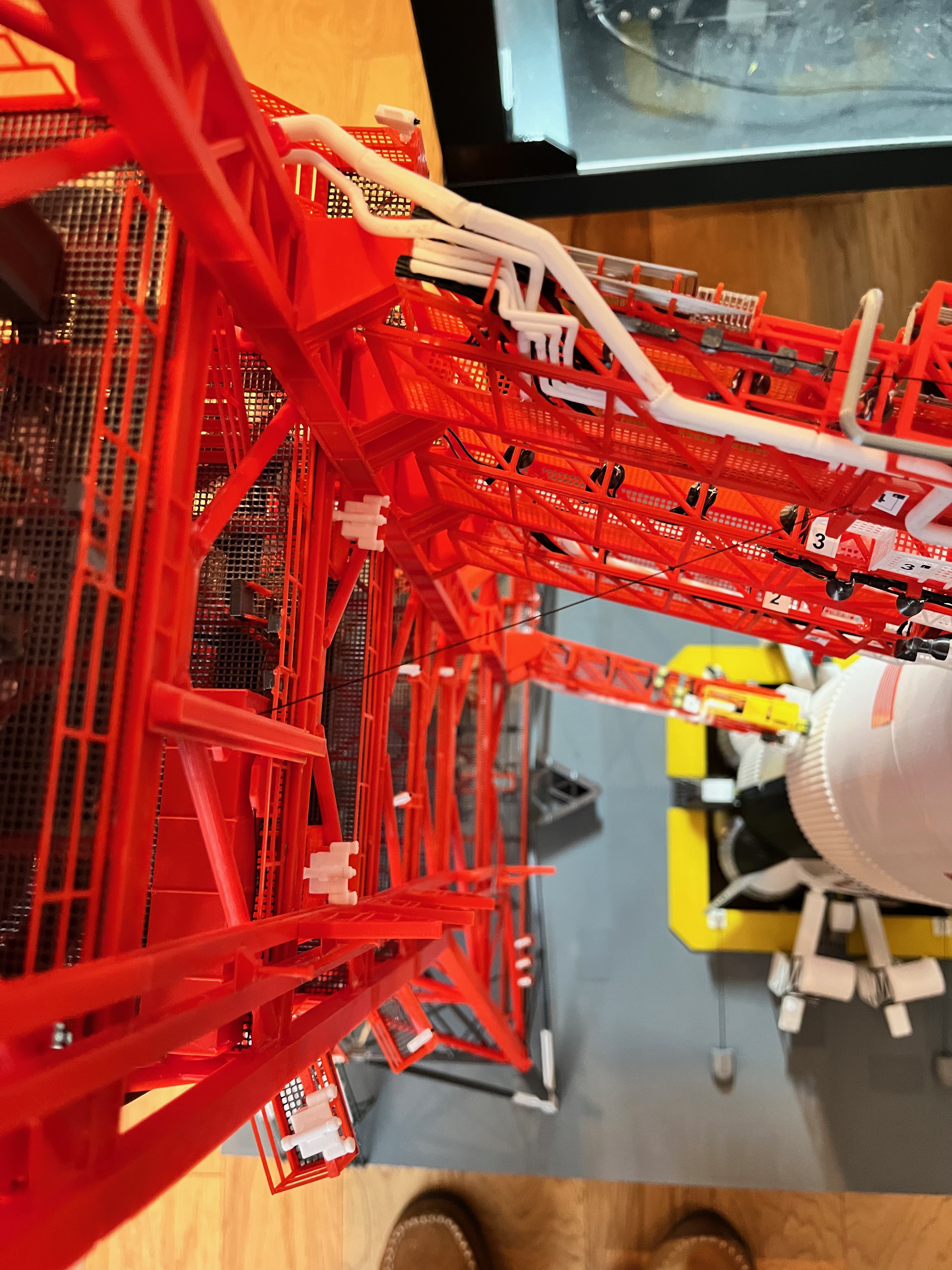
The remaining parts for Section #3 include the side deluge pipes and the Swing Arm #4 retract mechanism. Aviator67 provided a great looking box that contains the retract mechanism, but how does that connect to the swing arm? The MicroArtwork provides the answer. There is a cable that pulls the arm over along with a set of pulleys, two of the pulleys mount to a vertical box beam. You can see that I use the tiny drills and skills learned from building the ship model to drill holes into the plastic, then fill the holes with glue and insert a thread end that simulates cable. You can just see the thread going over to the swing arm in the top down picture. The pulleys and their holders are small enough that it was all but impossible to print the actual pulley.
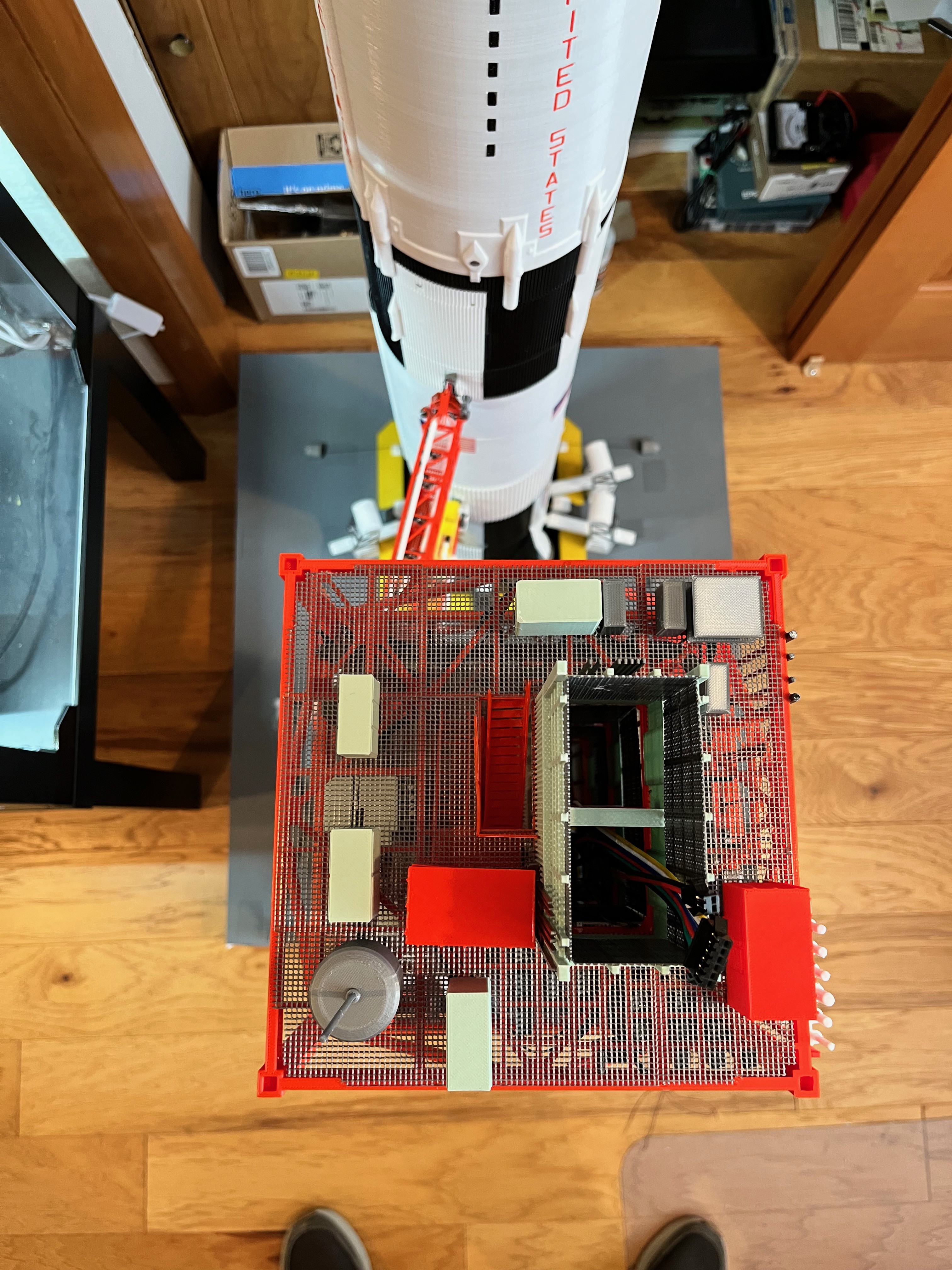
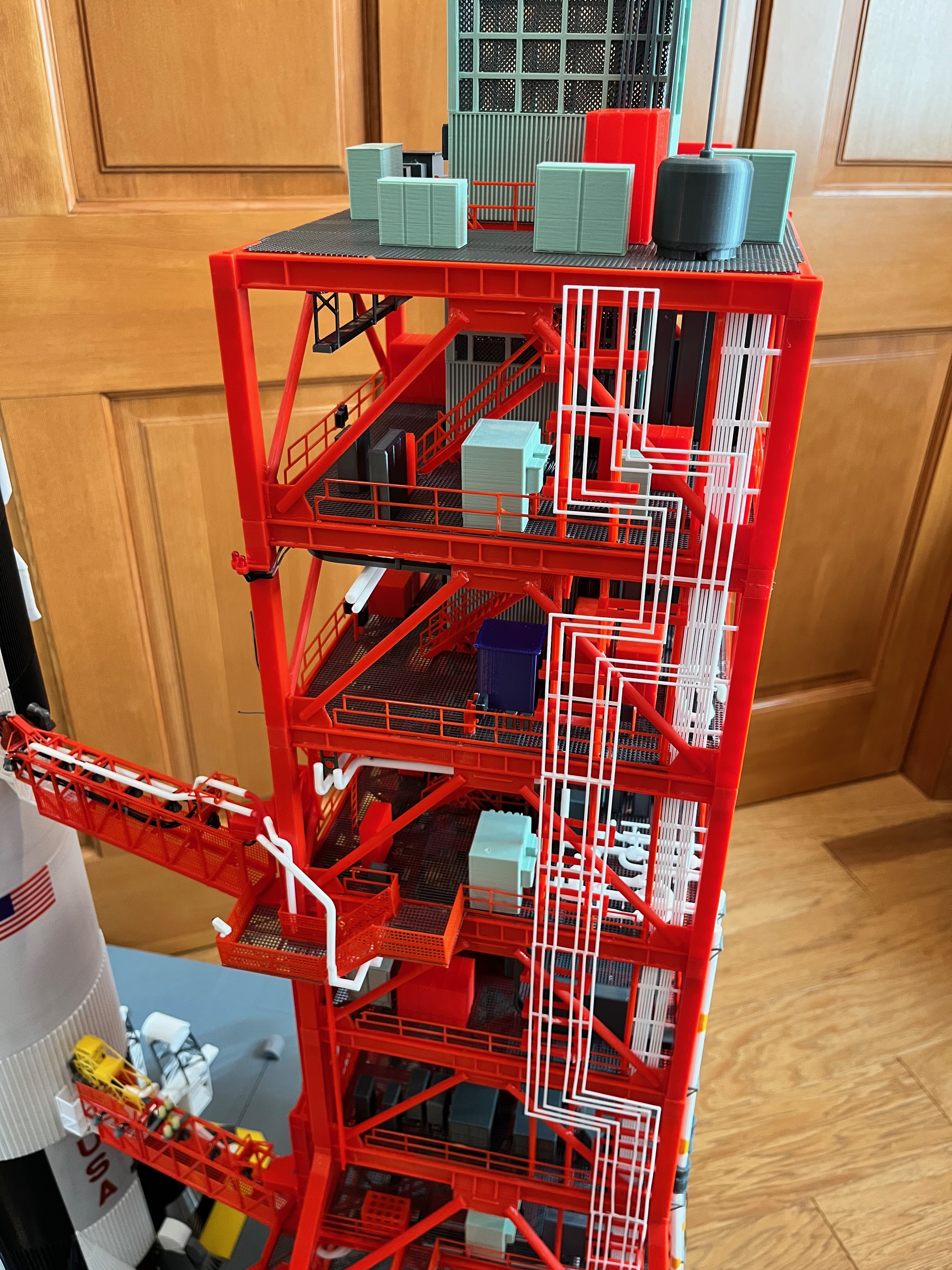
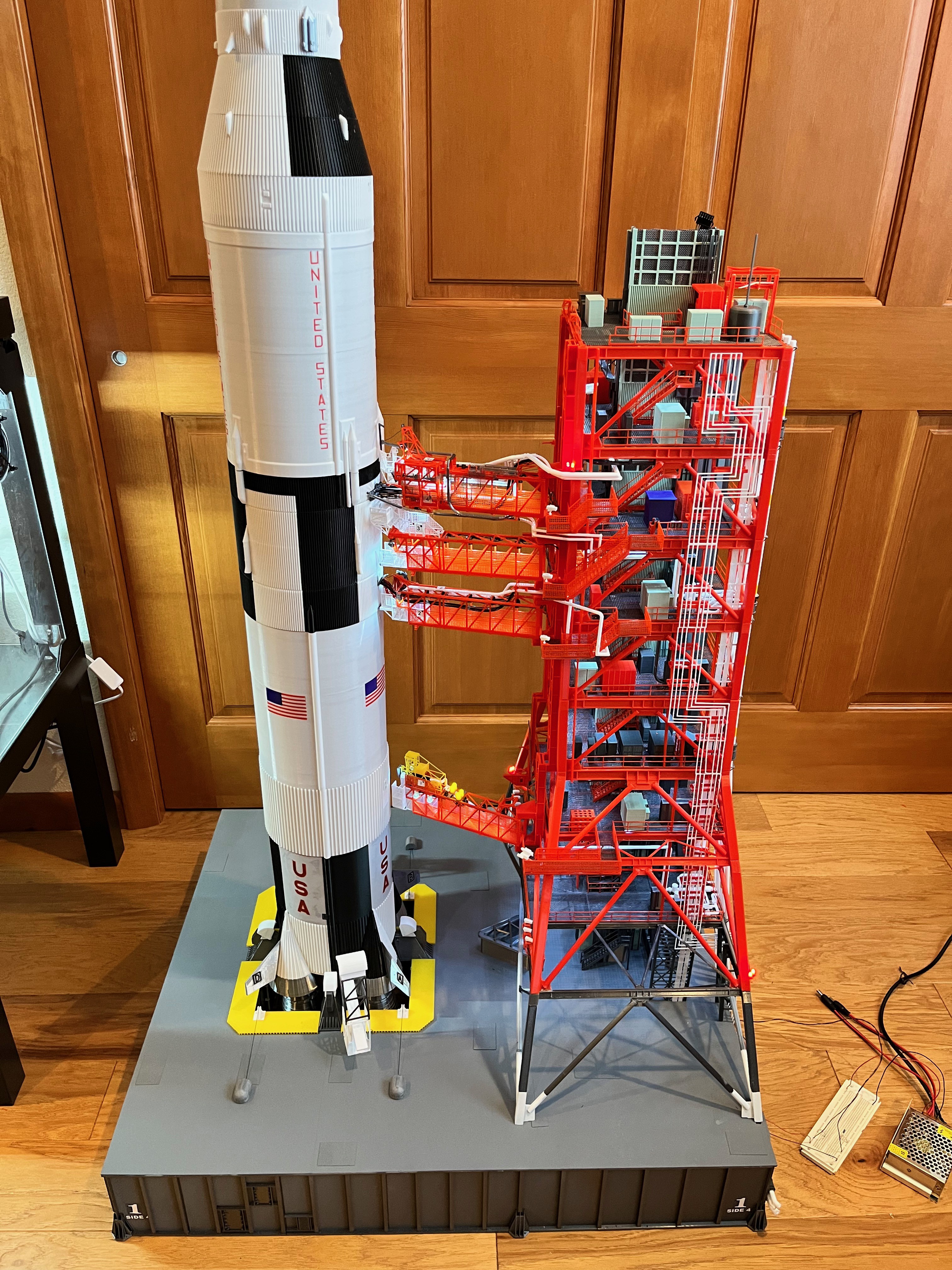
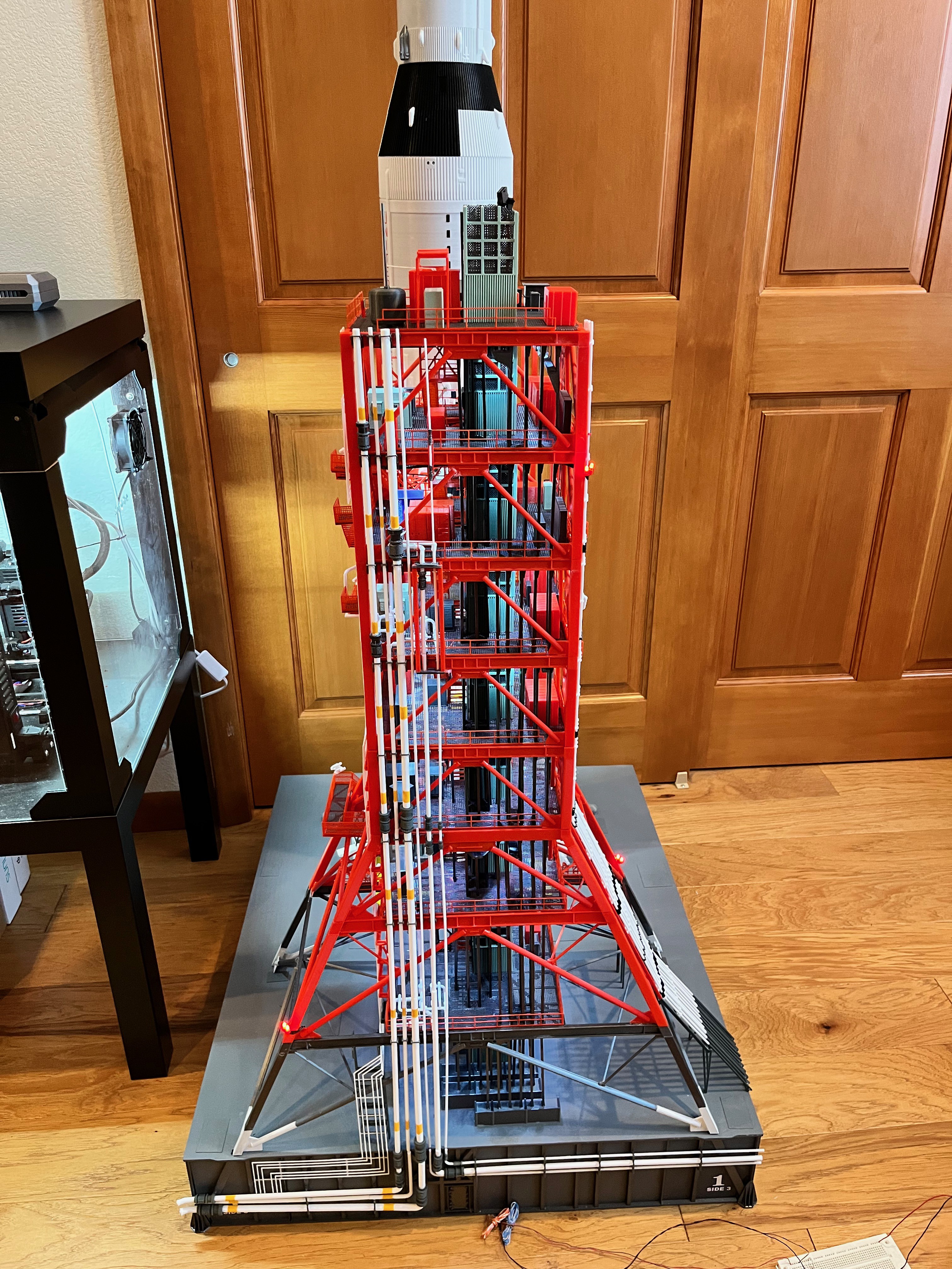
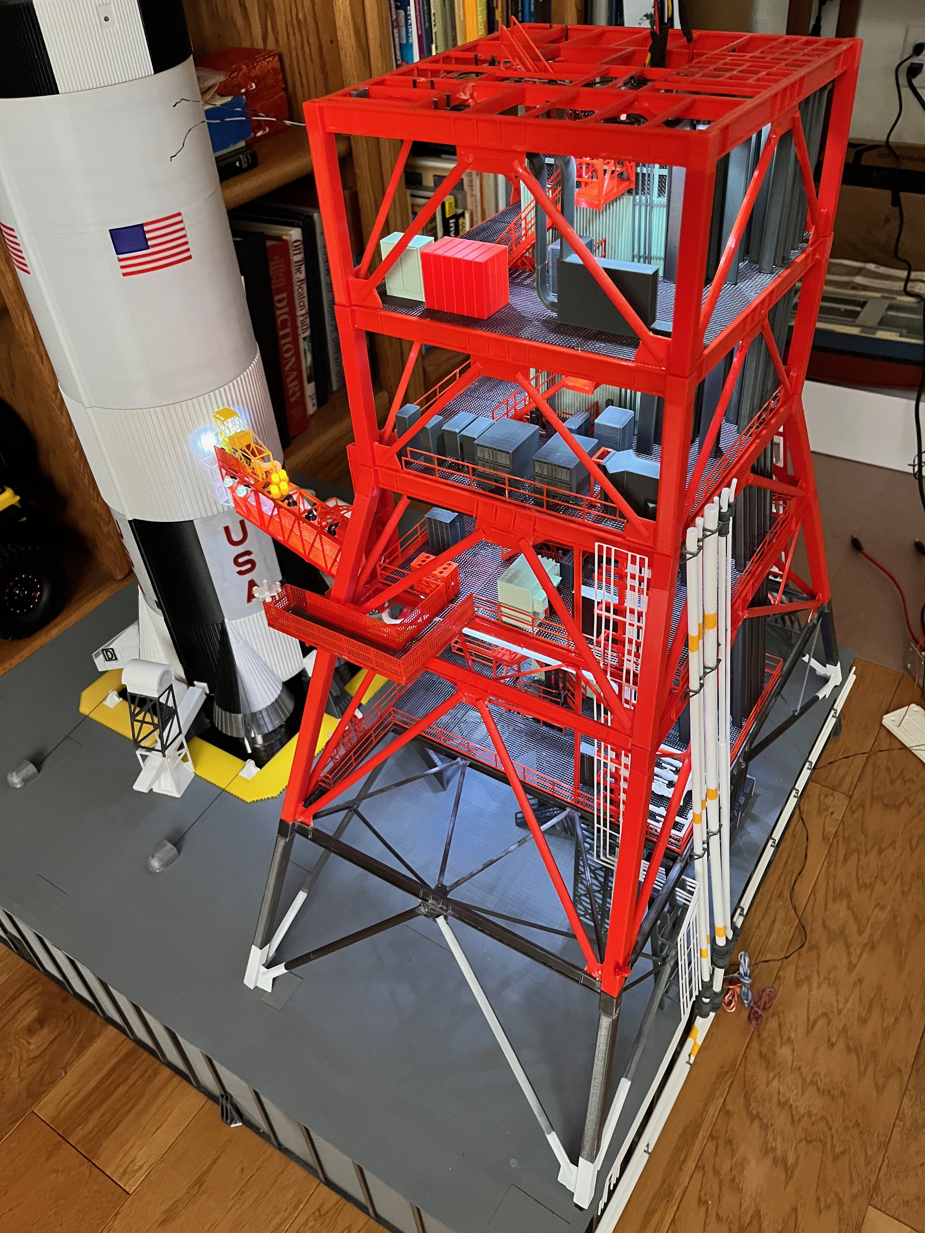
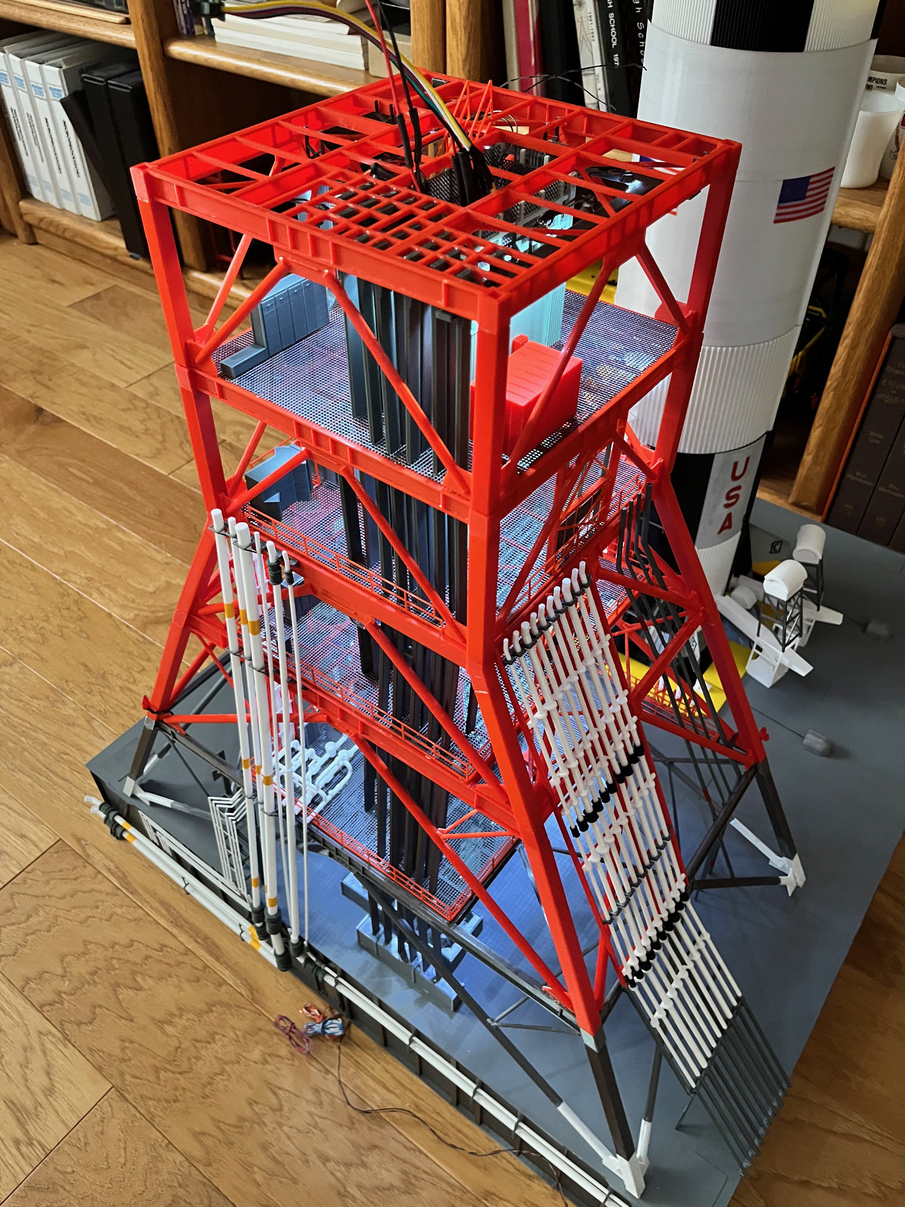
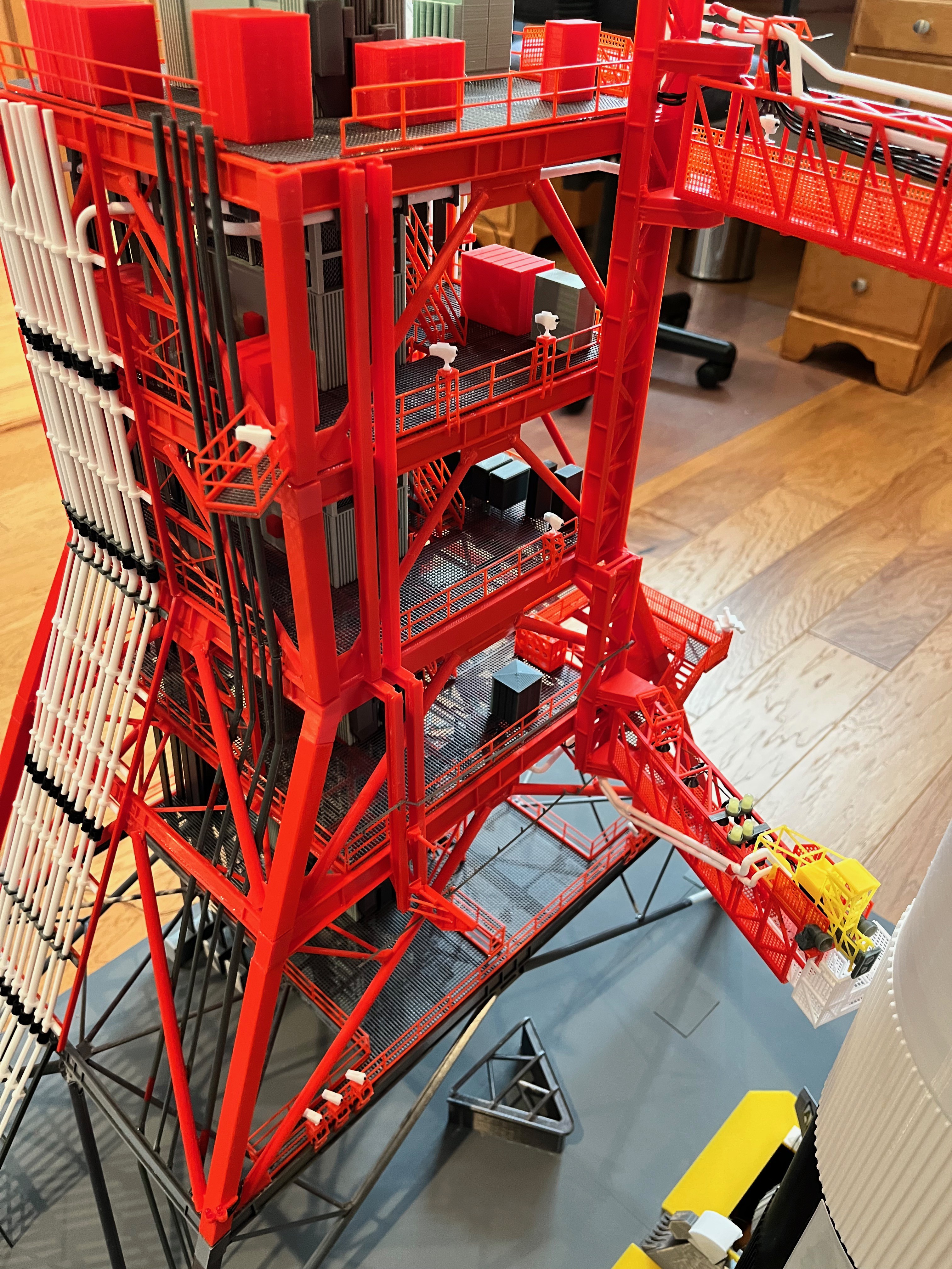
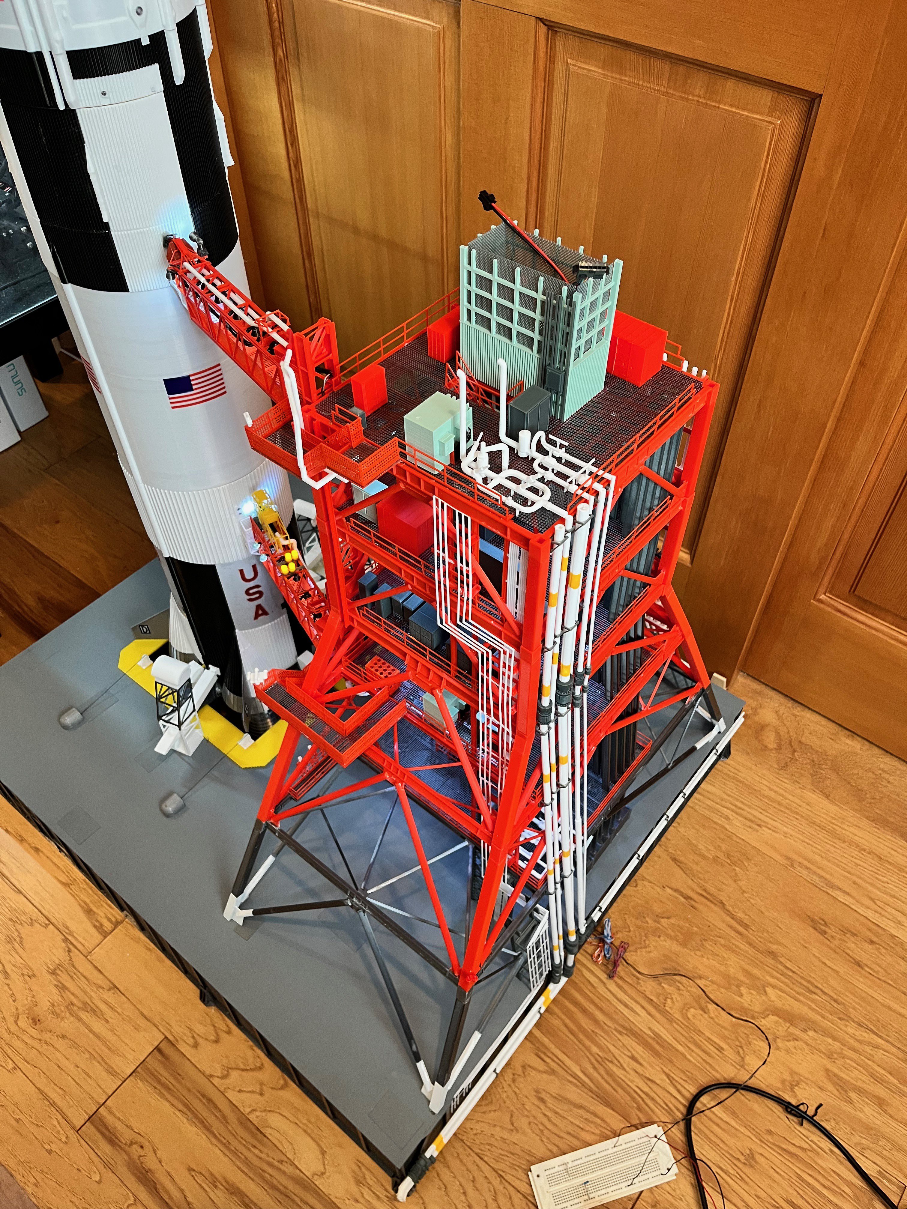
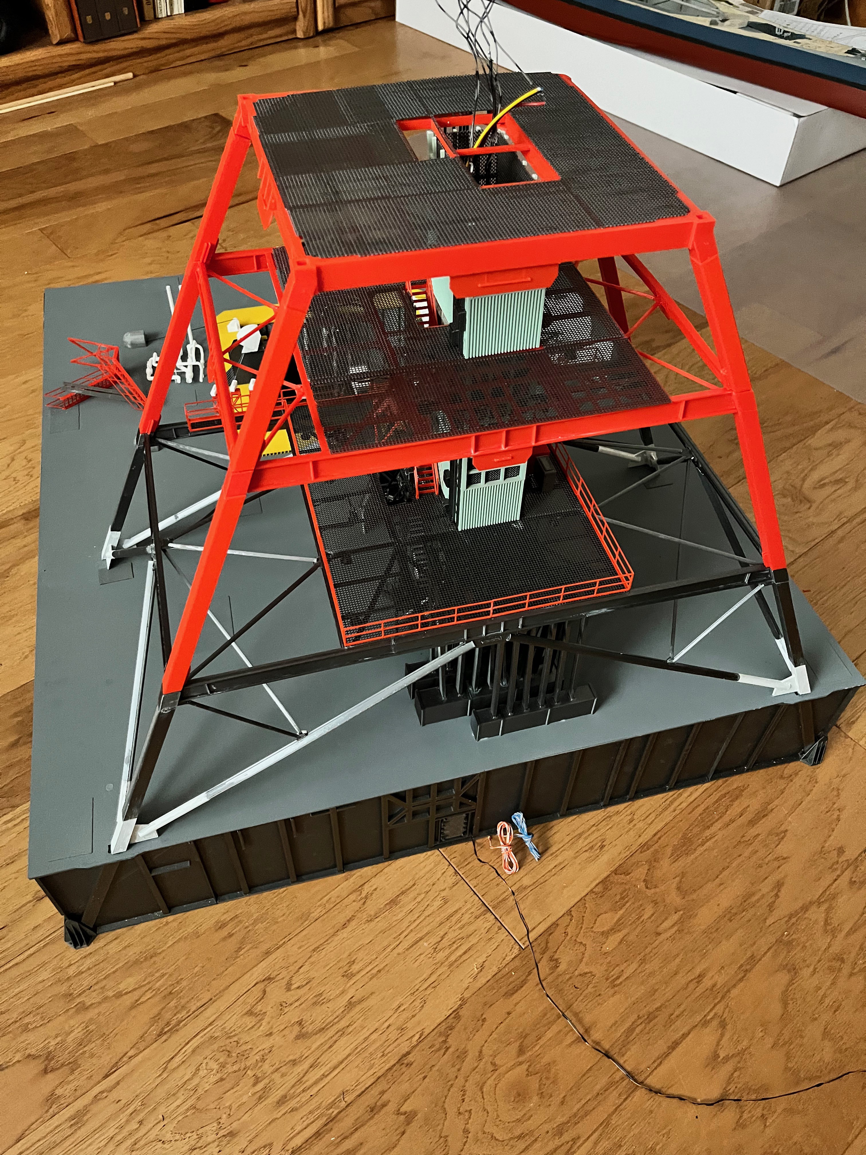
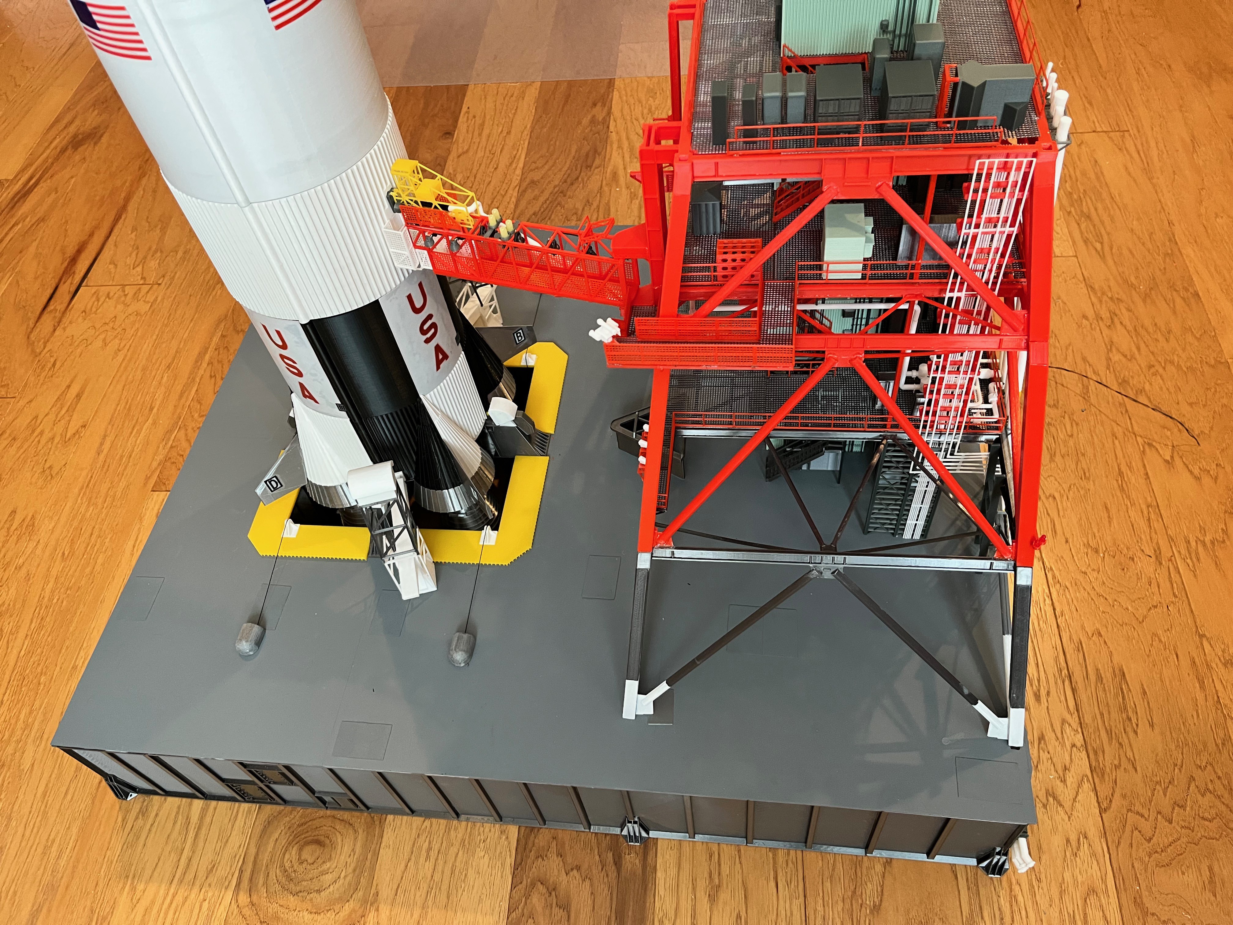
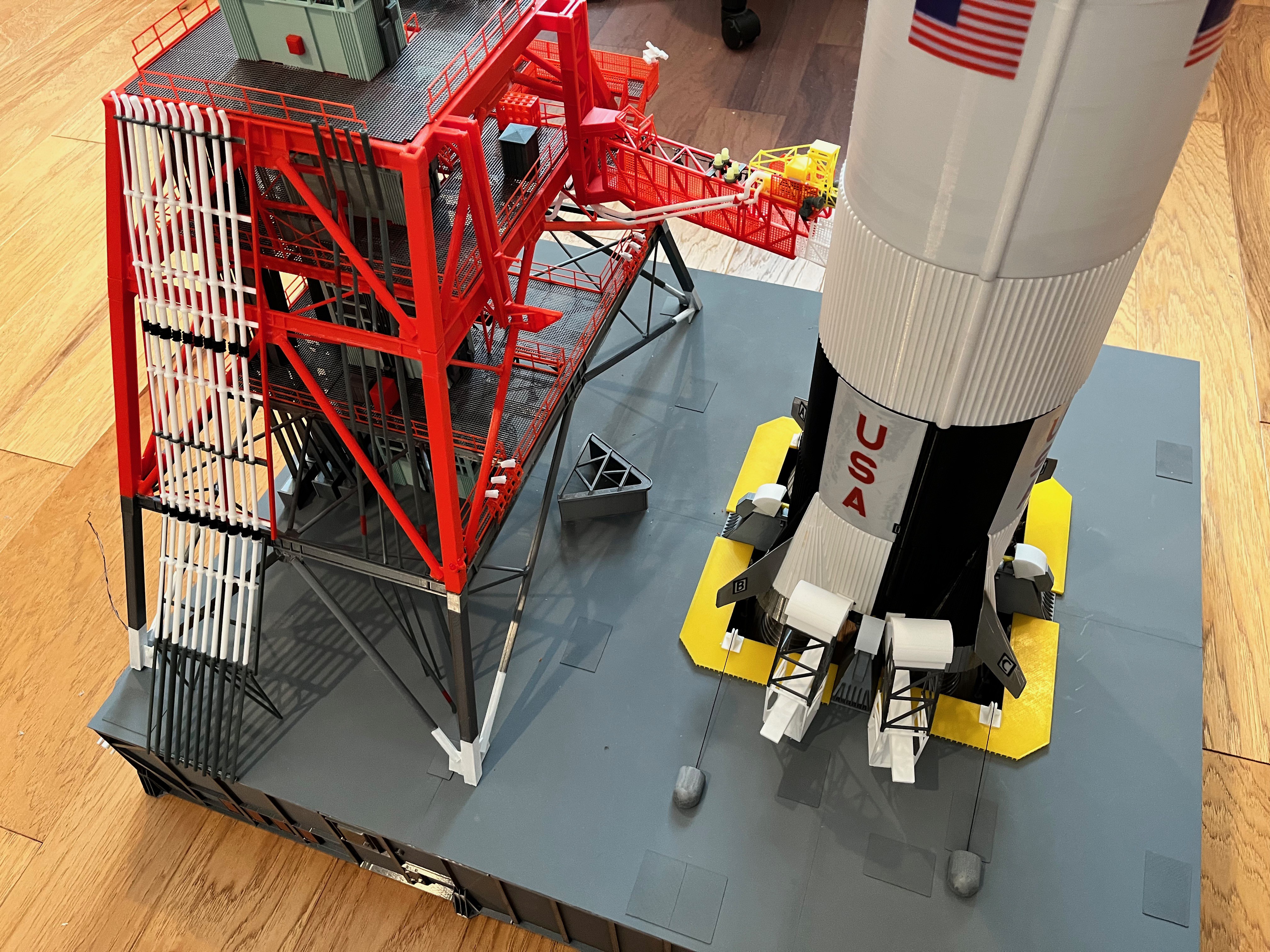
Section #3 of the tower is now complete! This is a significant milestone because this is up to level 180 which means the tower is half complete, at least in height. Here are pictures of sides 2, 3 and 4 with the lights on along with an overall picture of the entire model.
So far so good. The structure, flooring and elevator design has held up. Per a previous post I did some refinements on the stairs. Between levels 100-120 the cable trays that dropped down to a box needed to be shortened. The lights are looking good. I realized that from these levels up each level has 12 lights, not 13. The first two levels had a light over the stairs and I was continuing that. From now on I will only add 12 lights per level. Before I hang the ECS pipes under the level 120 floor I will need to add the ECS pipes to the outside of side 2.
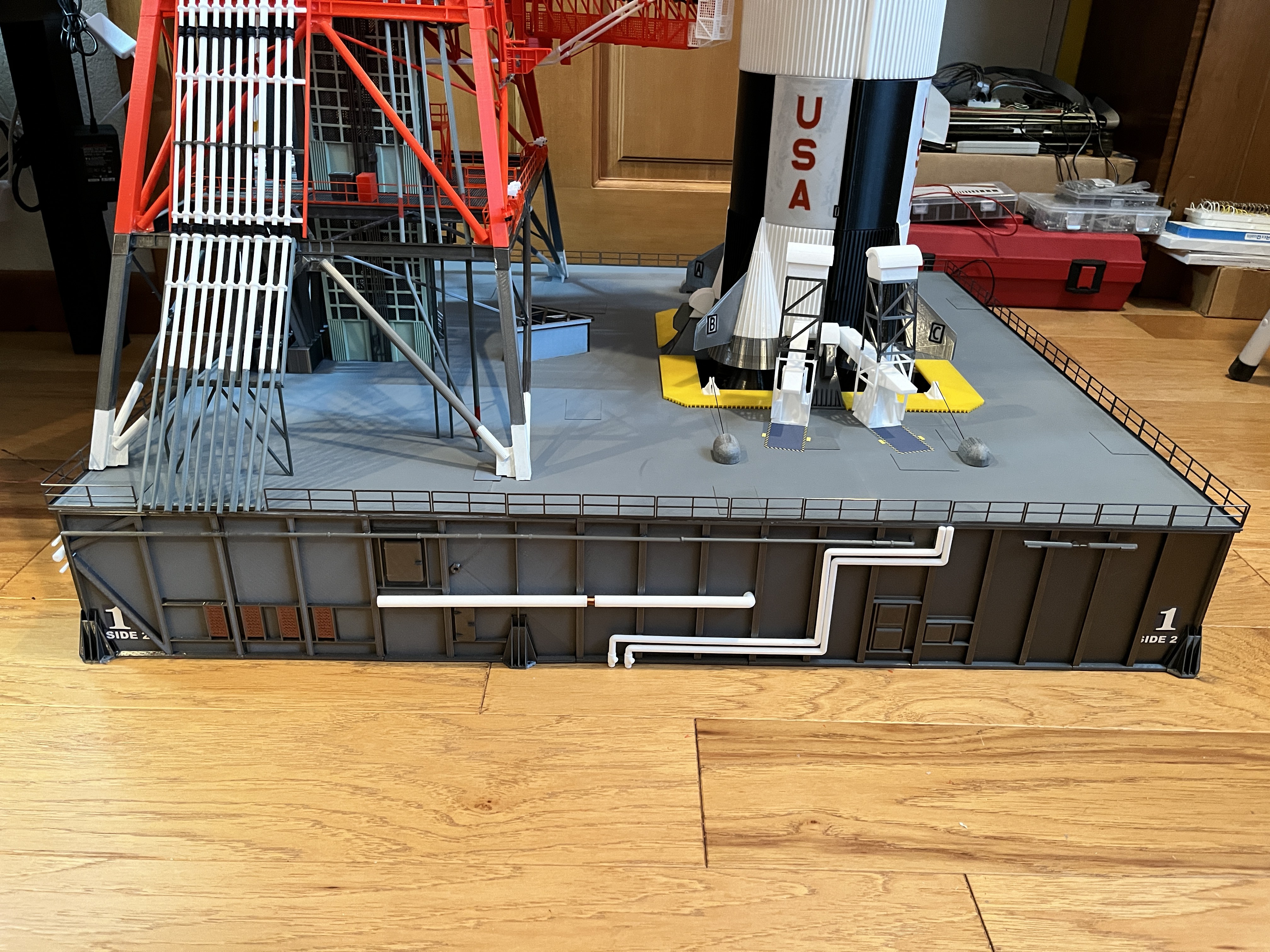
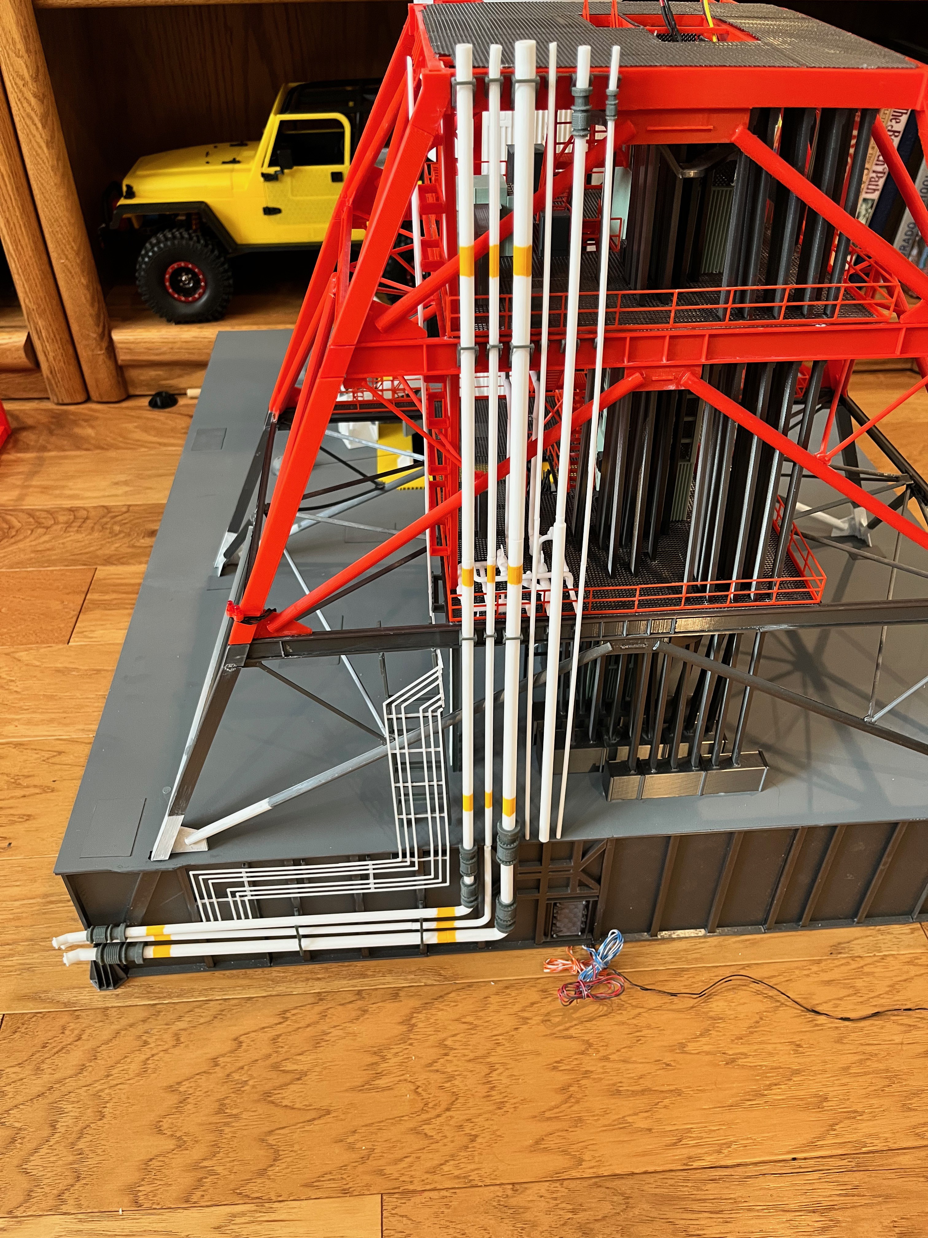
The ECS pipes are in, including the two (E7 & E11) that go over towards Swing Arm #2. In the first picture you can see that it takes some doing to get things lined up before gluing. I only used 6 hanger brackets because of other various parts and wires in the way. I had some minor parts updates to get the pipes just right.
Section 2 of the tower is now complete except for Swing Arm #2. Notice the camera platform at level 100.
Swing Arm #2: The parts are designed and printed. Working on assembling them. Black wire is used to model the cabling. I still need to paint some flexible tubing and connect up the end, get the arm attached and attach the walkway.
Tower Section #2 and Swing Arm #2 Complete: The next removable section of the tower is complete. This completes right at 1/3 of the tower! The first stage of the rocket can now be fueled. The swinging arms are working well. This section added 5 cameras. All but the Side 1 photo have the lights on. I am happy with the lights. Swing Arm #2 is now published. Looking at the zoomed in pictures I just realized the walkway stairs to Swing Arm #2 are oriented incorrectly. Oh well. I will probably leave them this way. It would take quite a bit of work to remove and replace the walkway.
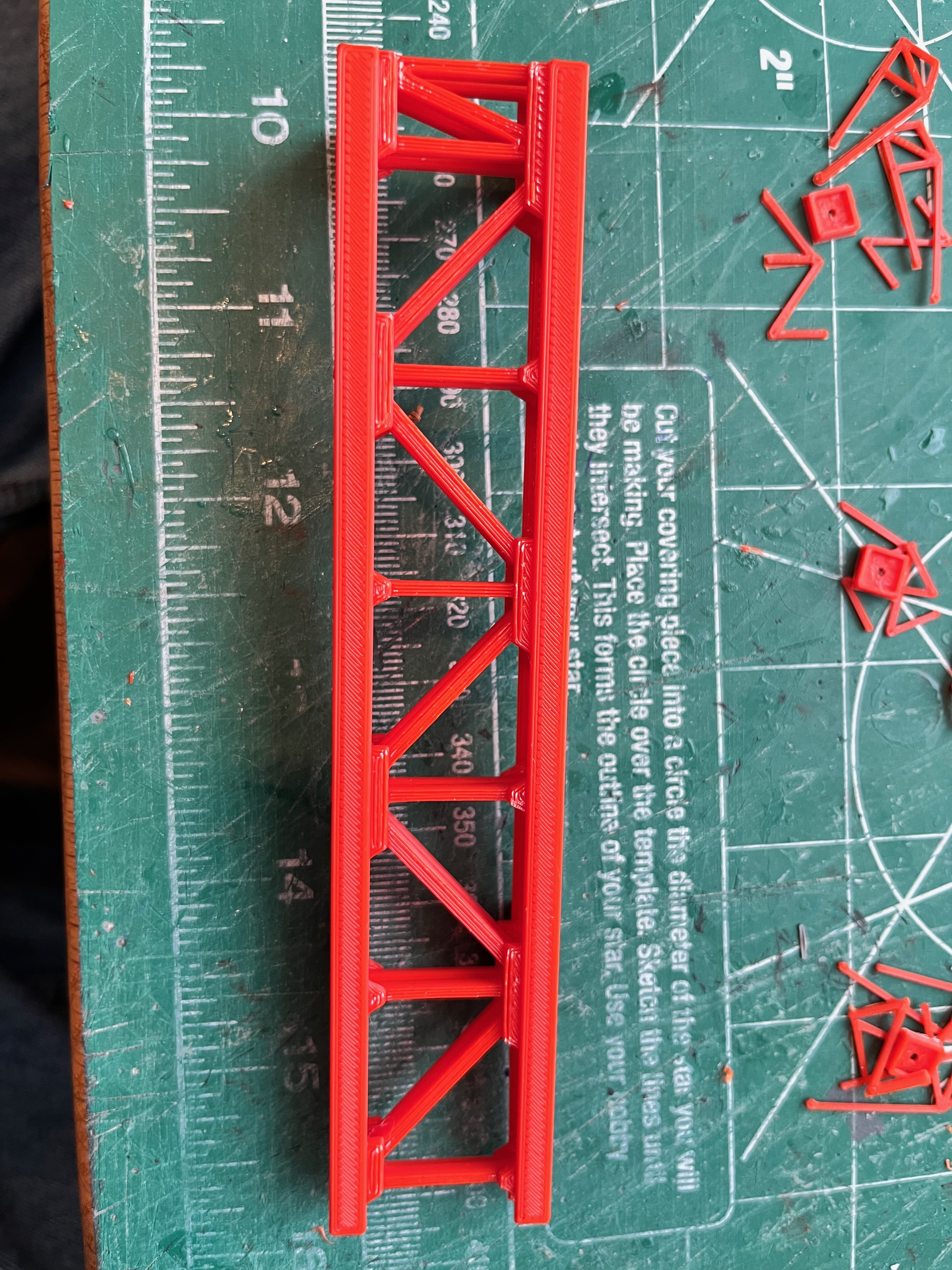
Swing Arm #1: I have started designing the first swing arm. The hinges are already designed and printed. The first thing I did was measure the distance and angle between the hinge pivot point and the connector on the rocket. With a hand held protractor and a 6" ruler I was able to eyeball the angle at 73 degrees +/- 1 degree. The actual measurement should be 72 degrees 13'-36". The length should be 452.02" which translates to 191.36mm. The actual measurement is 188mm which is within 1.75% of the actual measurement. I couldn't be more pleased with the results. The launcher and tower have to be pretty close to exact to get these results. This means I can go with actual measurements and take advantage of the sliding components that bridge the gap.
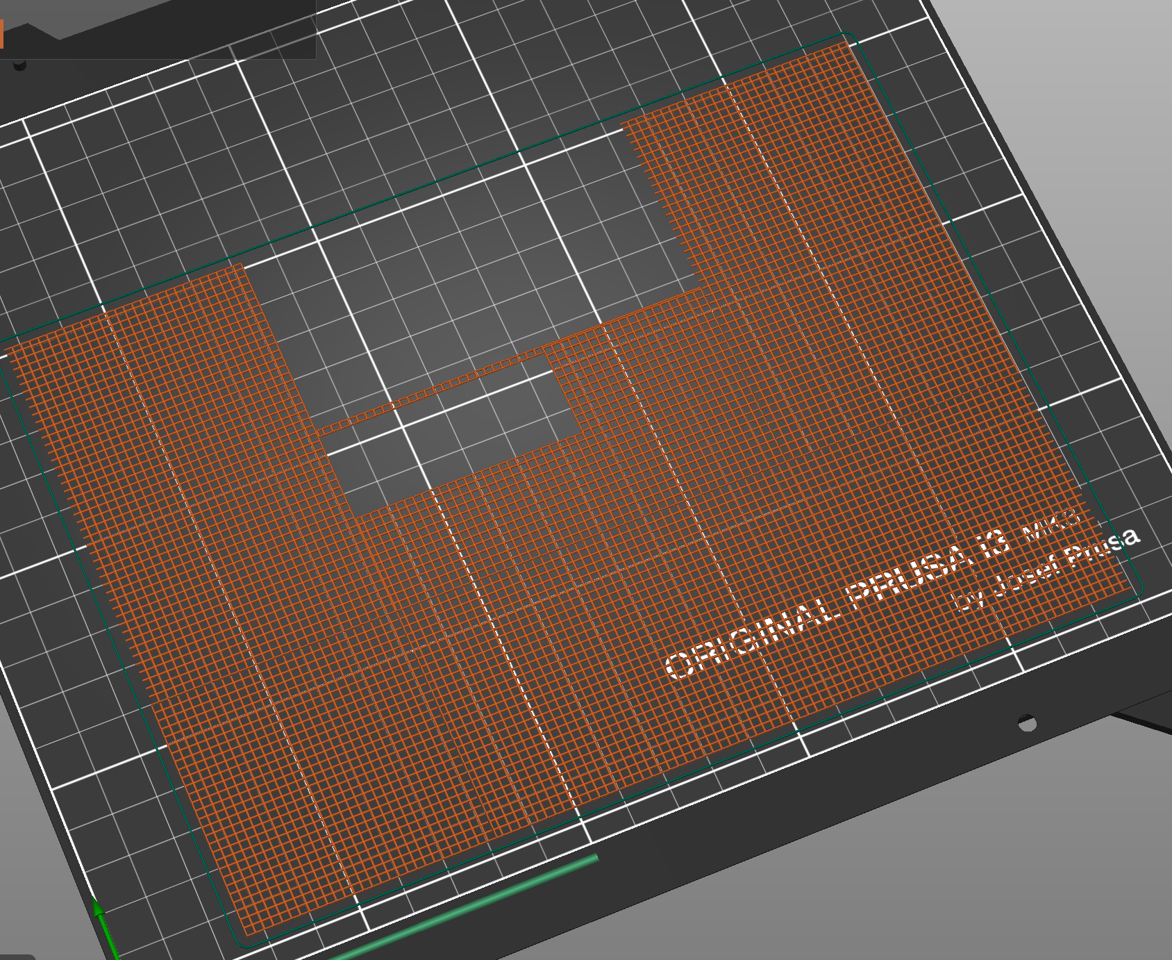
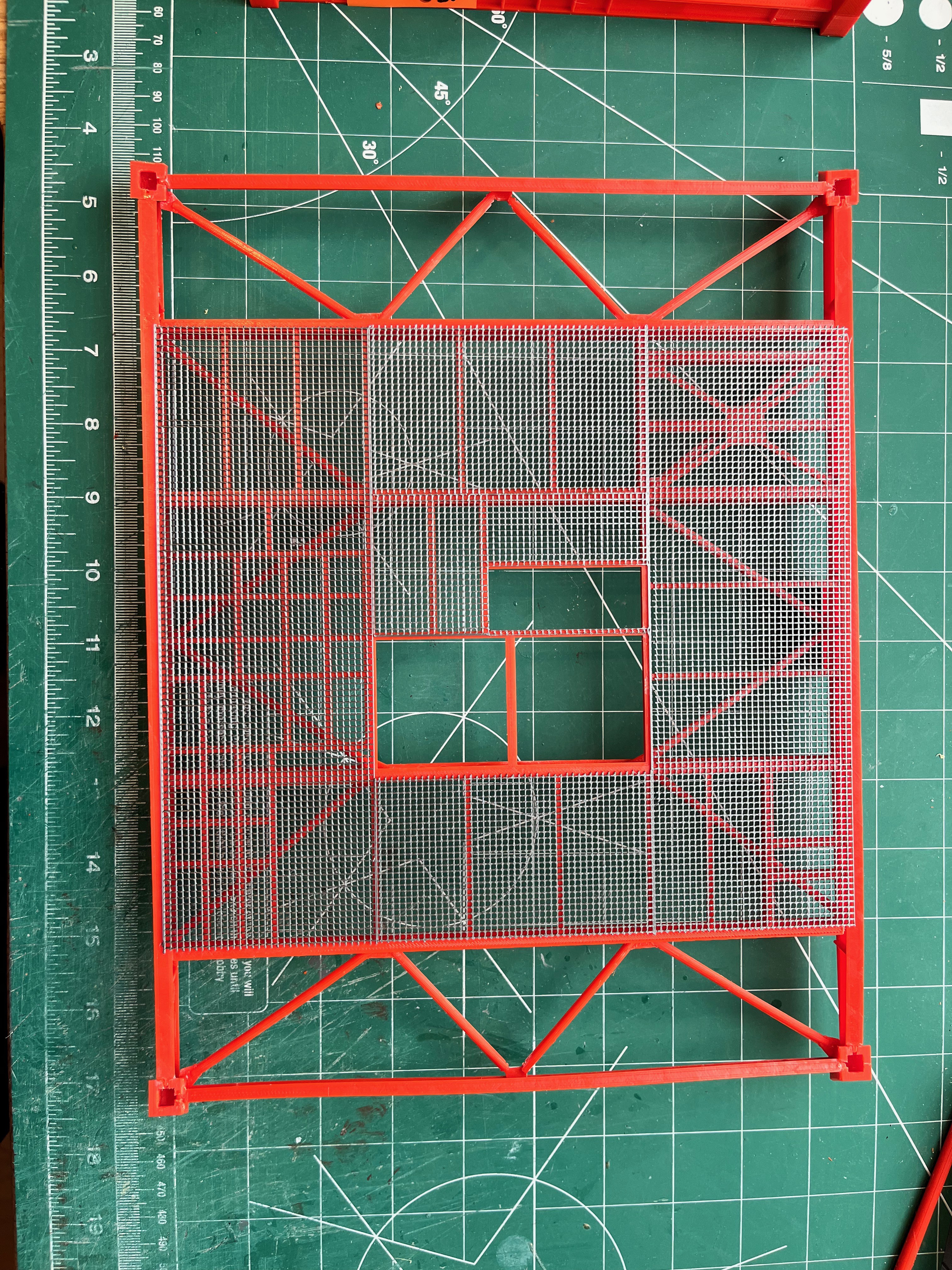
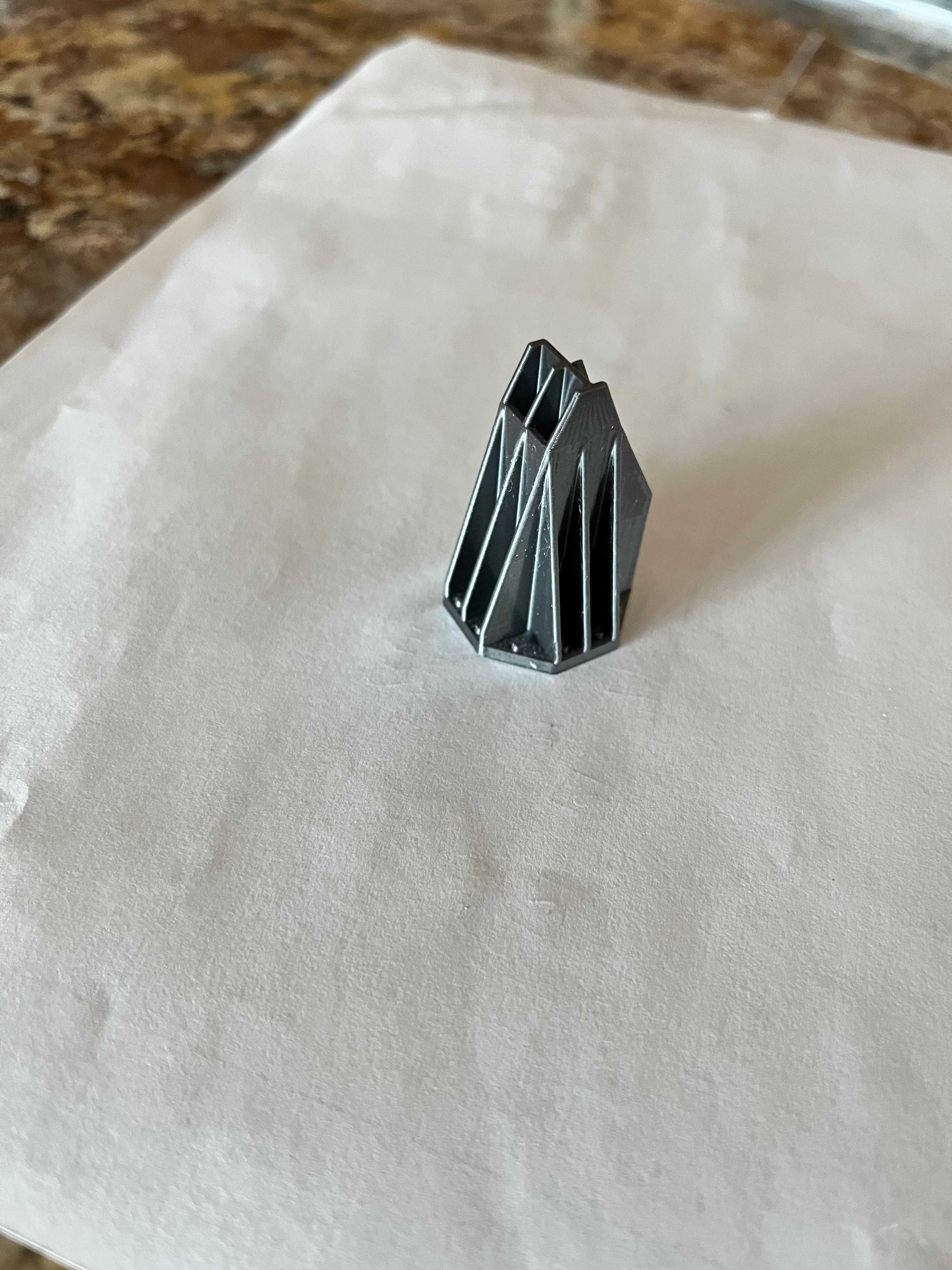
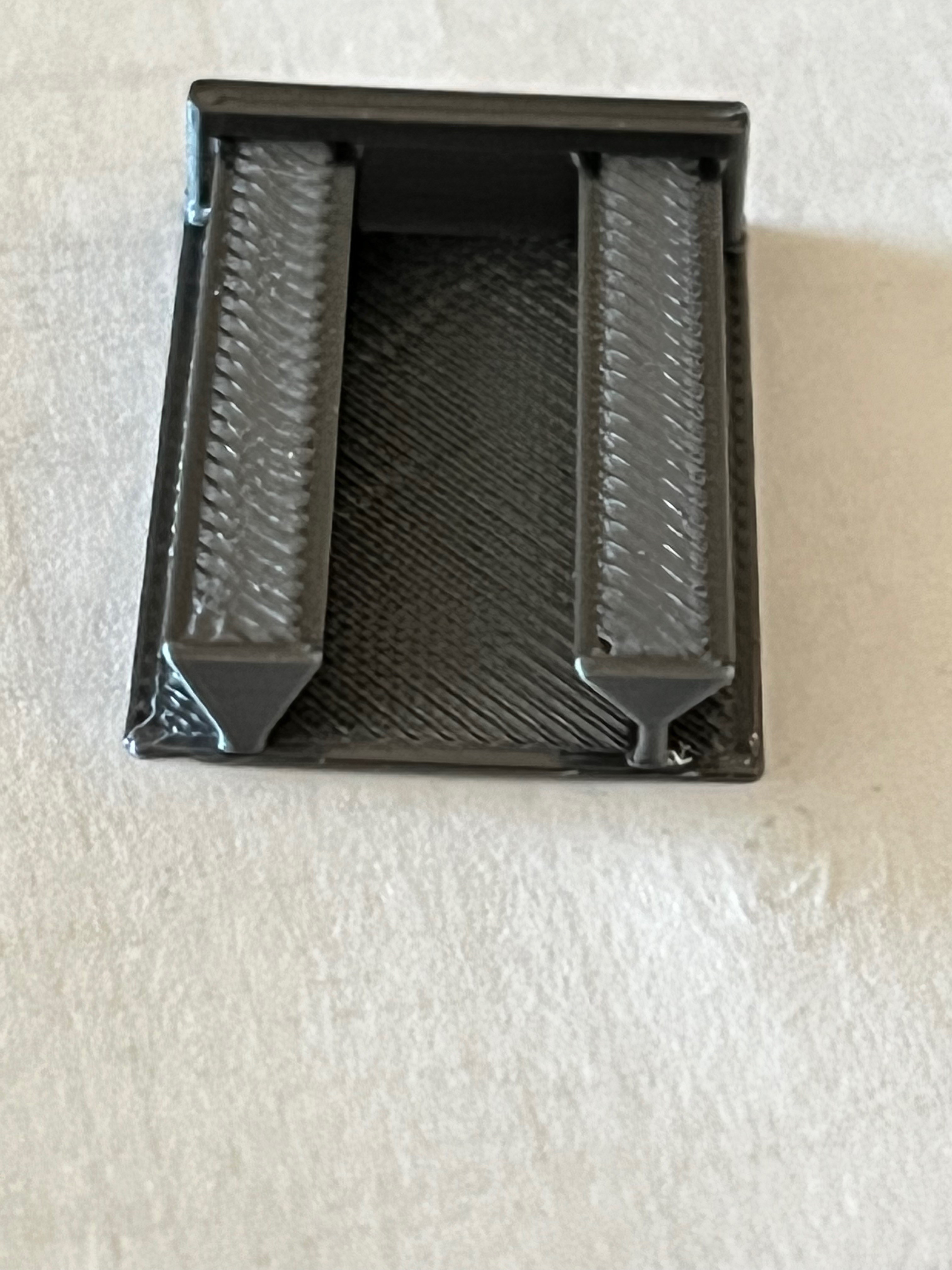
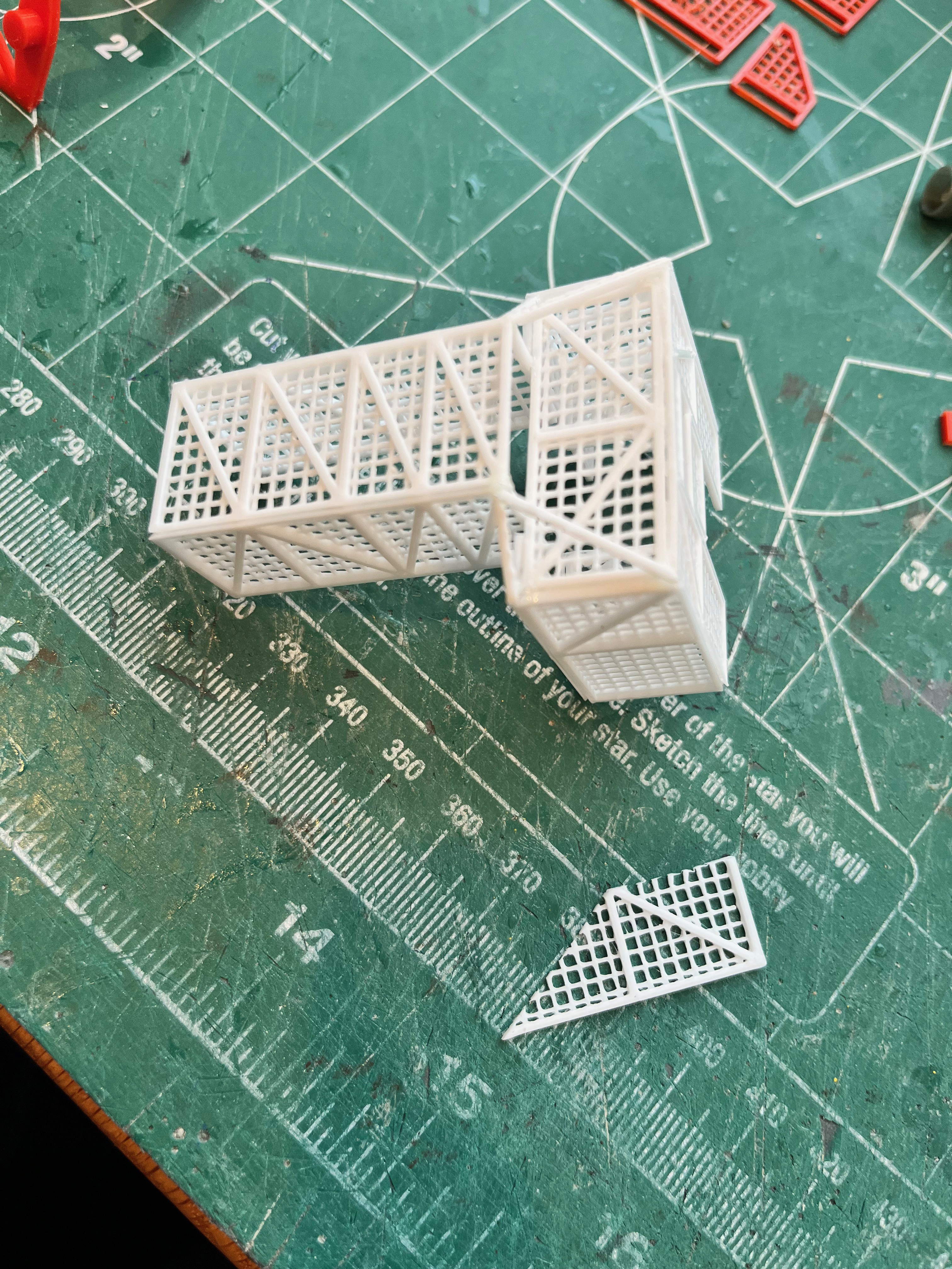
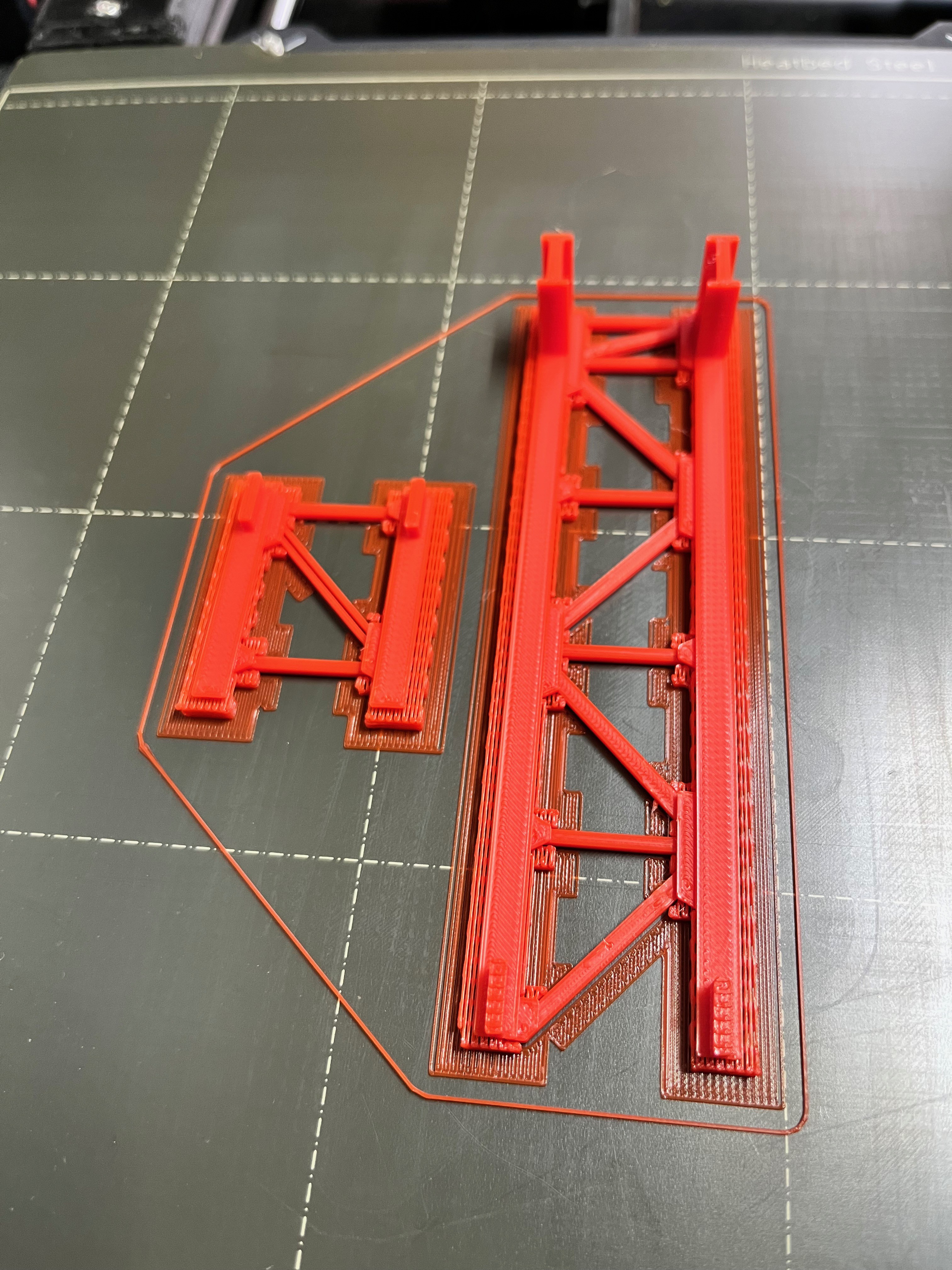
Here are pictures of a test print of the first and second elements. I used some "Galaxy Silver" filament that shipped with the printer, something I would never use in a model. The cross beams are round and everything else should be angle iron, but like before I squared those off for strength. These arms should be light and airy, not something that looks like it is made from Legos or something out of MineCraft. Lots of bling still needs to be added to these pieces. For the grating I plan to go with something even lighter than the floor grating. I will try a 0.2 x 0.2mm grating that is integral to the sides and bottom.
Swing Arm #1: I'm glad to be doing something more exciting than pipes. The swing arms are detailed models unto themselves. I suggest you get a good pair of tweezers and a lighted magnifying glass on an arm.
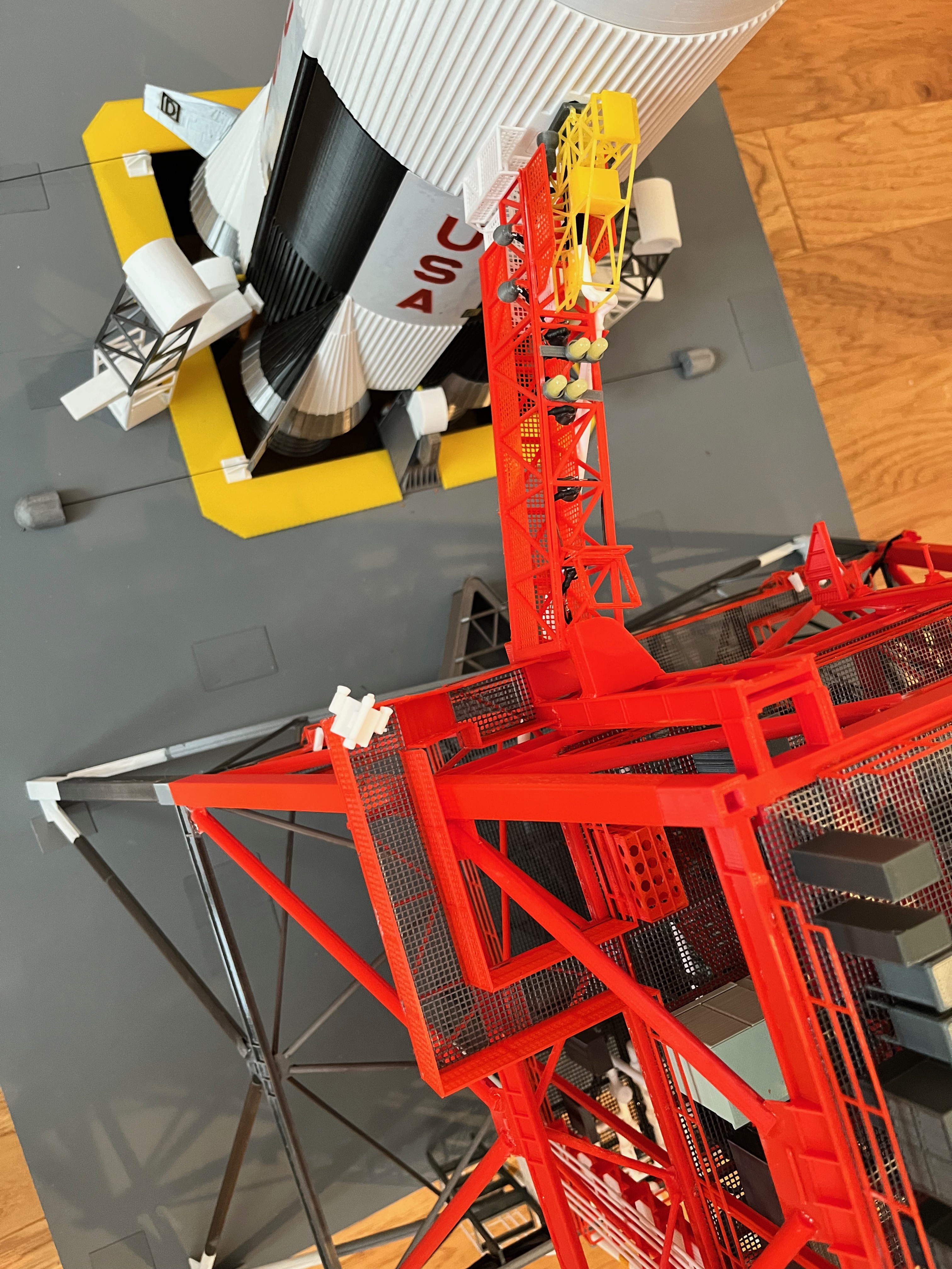
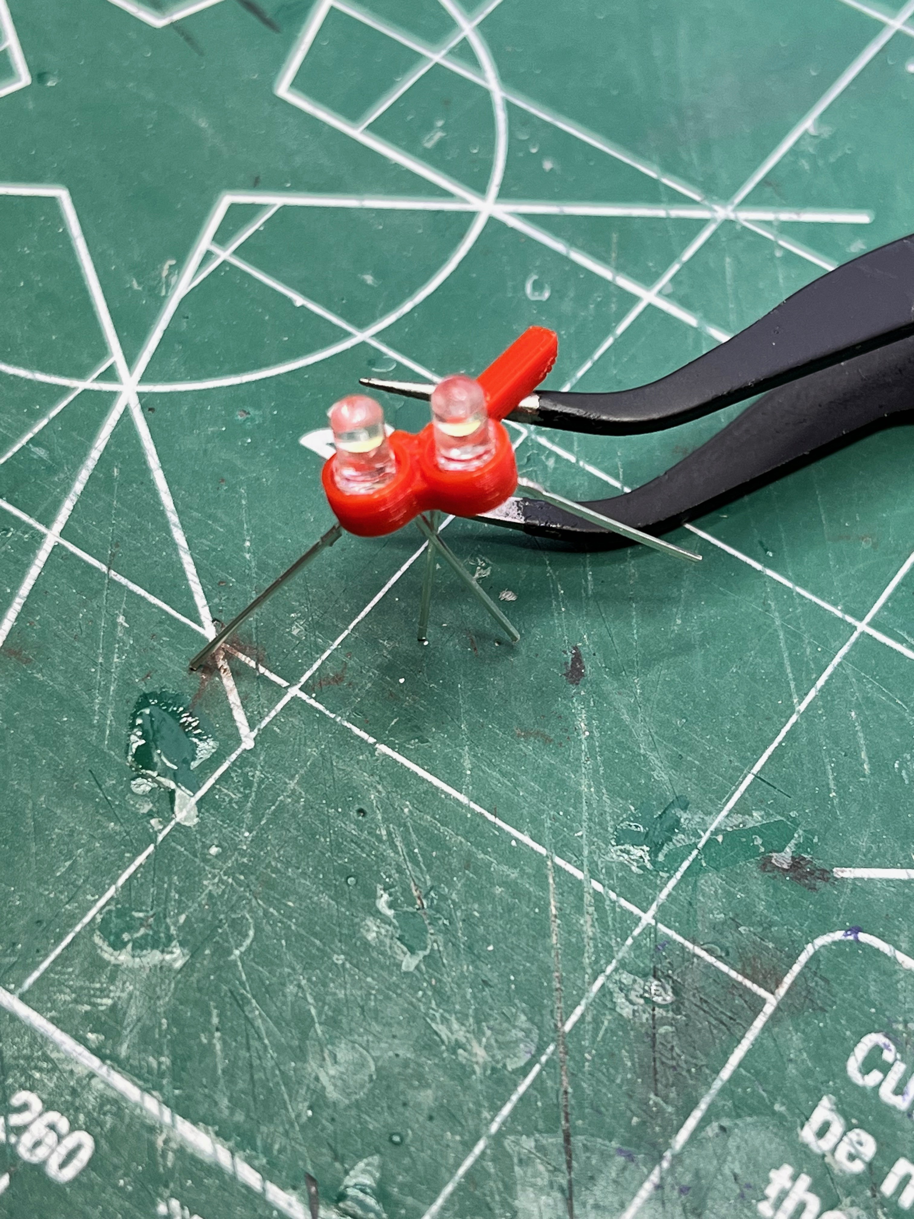
The yellow lights on top of the arm should be 3mm. I had some leftover 5mm LEDs so I used those. They are a bit too large but I had them so I used them. When I publish the parts you will see I made holders for both sizes. The wiring was tricky. The wires for the spotlights needed to be snaked through holes smaller than the lights so I had to solder them in place. Start by gluing the sides to the top, leaving the bottom open so you have access to solder. Once the lights are glued in and working then you can glue the bottom on.
The white extension platform can be left unglued and adjustable. The parts for the swing arm are made to the original dimensions. My arm length is 3mm shorter than it should be. Fortunately this part can be adjusted to make up the error. I chose to glue in the extension platform, leaving a 2-3mm gap between the end of this platform and the rocket. This appears to be to scale and allows a gap for the arm to swing out of the way. On the underside of the platform there are support braces that go out to the corners. I simply cut some 1x1mm braces from a failed print. In the final parts you will notice some 1x1mm straight pieces to use for these braces.
As for the upper yellow structure I am calling the Fueling Mechanism (FM), this part was also made to not be operable. To have made this tiny structure operate would be in the too hard category. As you are gluing up the structure, check and double check with the arm held into place so the end just touches the rocket. I find it best to use slower setting medium or thick CA. Put glue on the surface, hold the part in place with tweezers and then shoot it with aerosol glue accelerator.
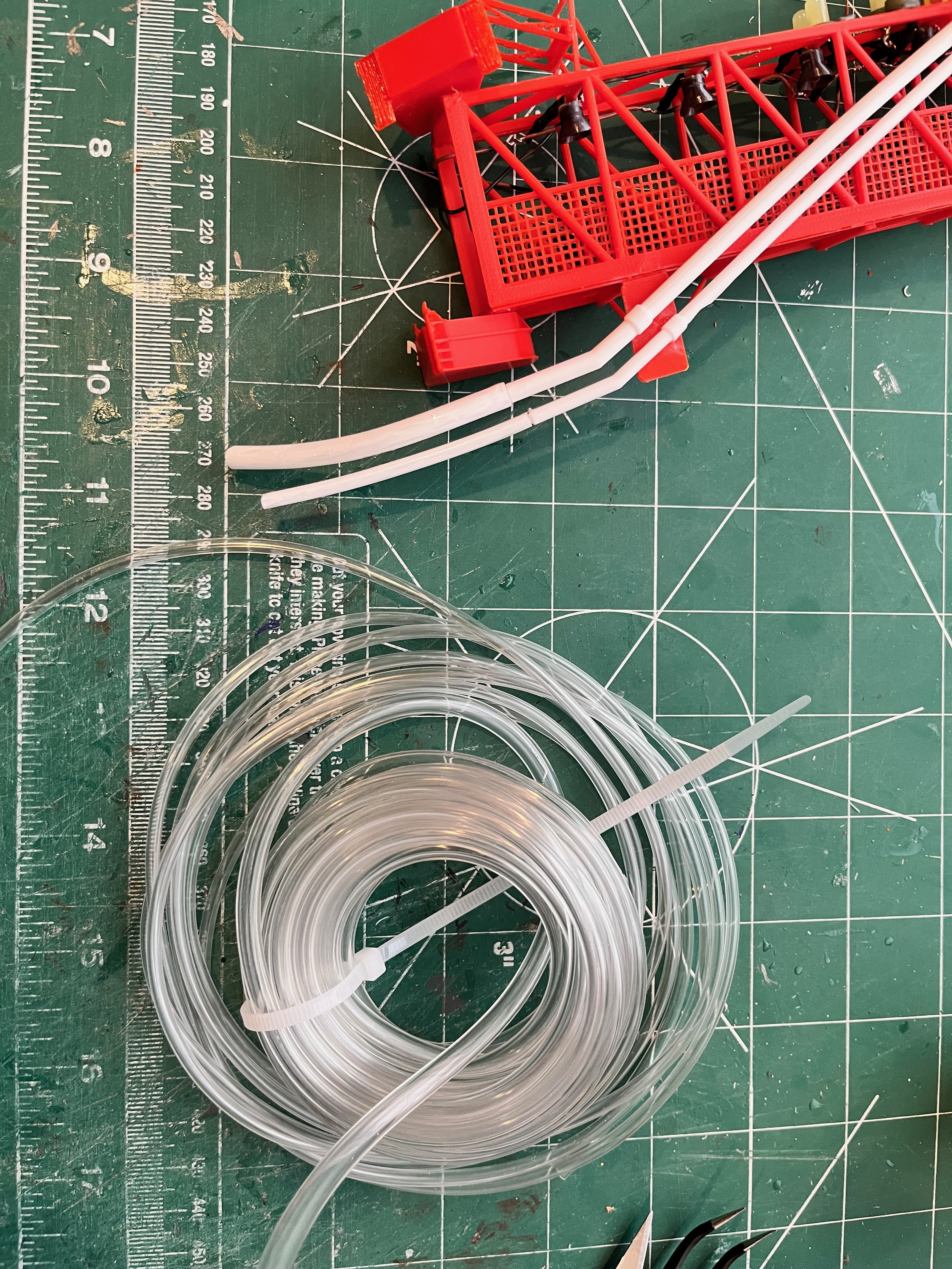
The tubing is a clear vinyl tubing, both 1/4" and 3/16" OD tubing. Fortunately this stuff is paintable.
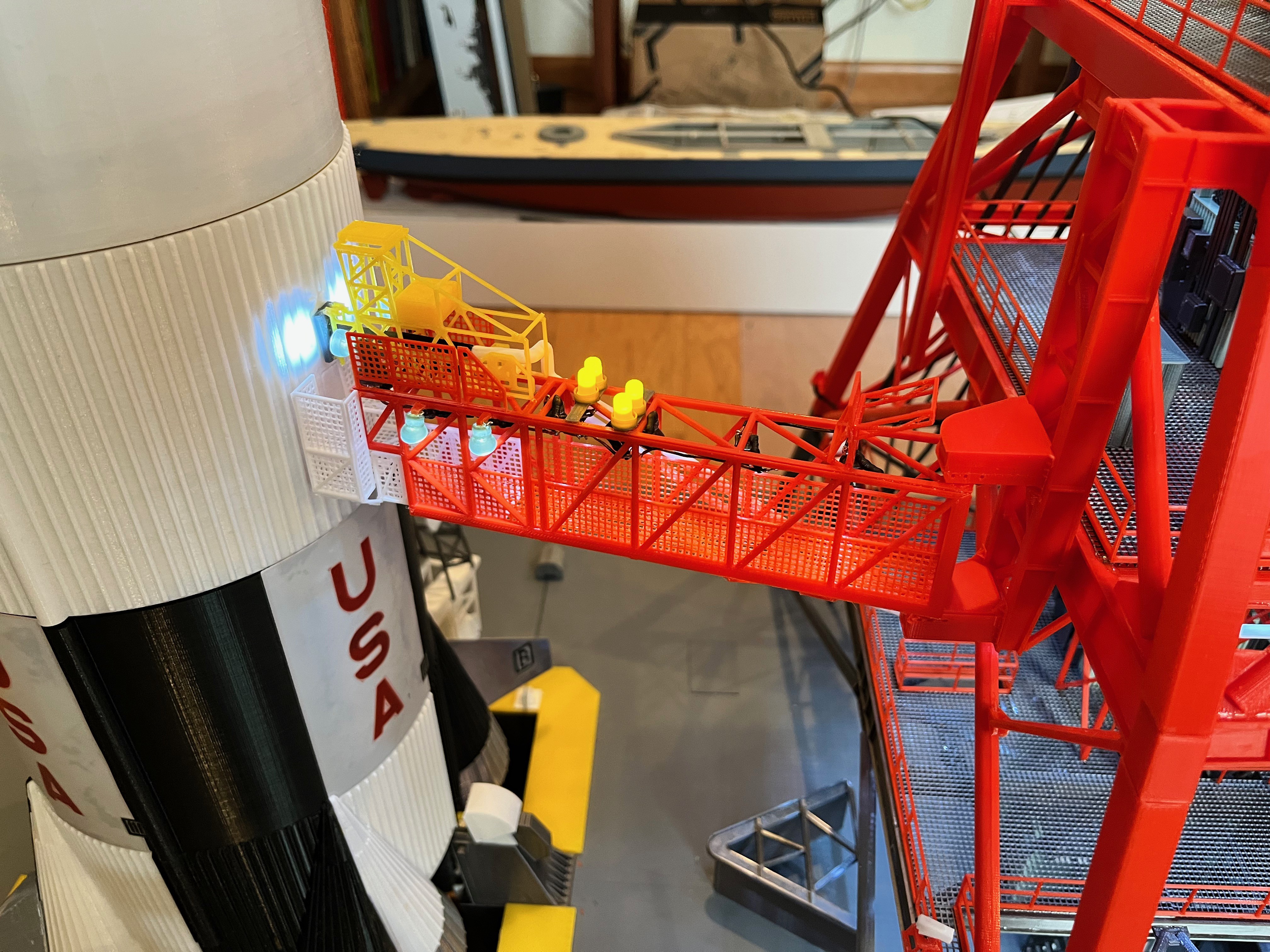
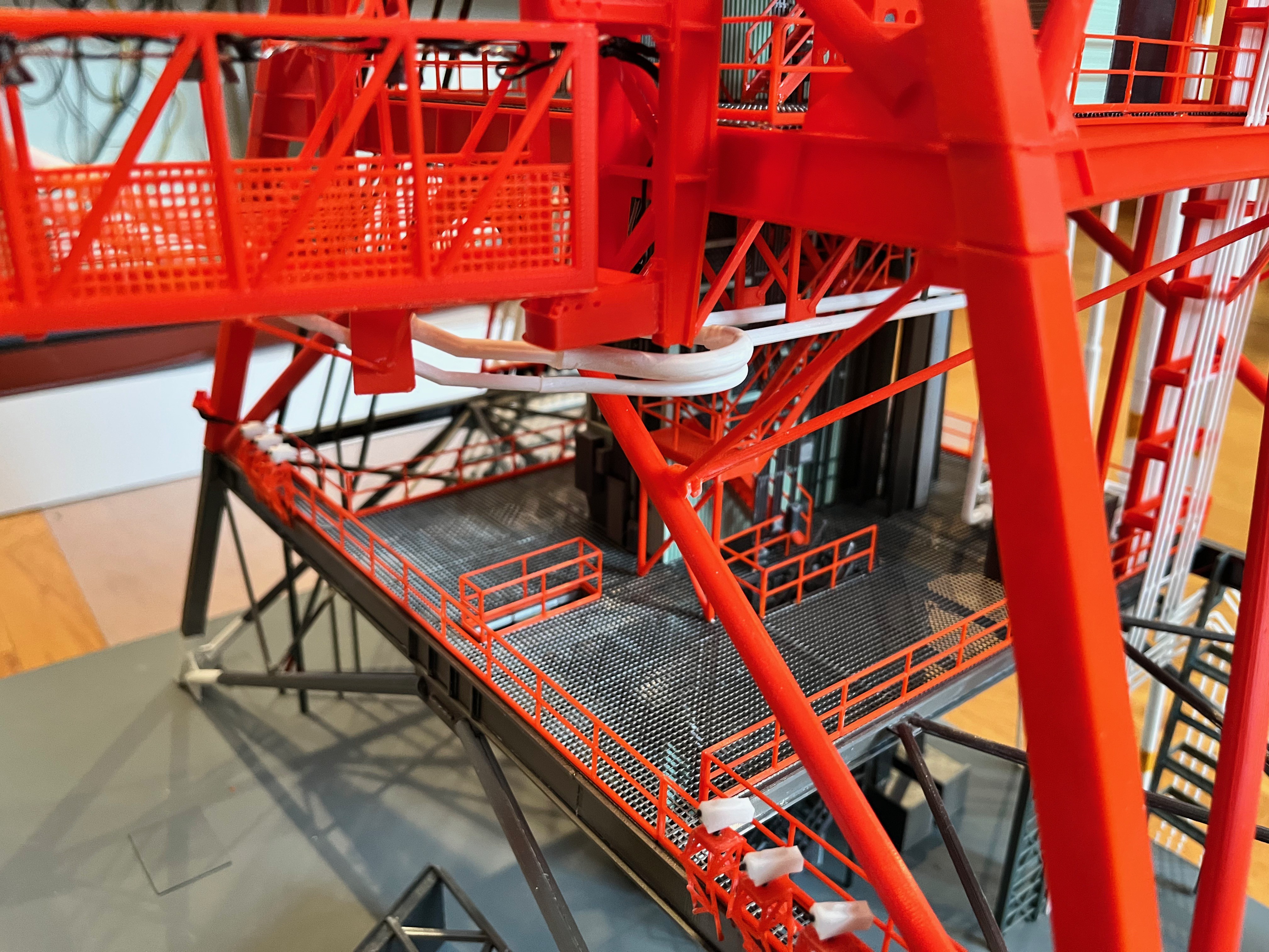
Swing Arm #1 Attached: The arm is attached! You can see a picture of it retracted and extended and lit. Four lights are in-board and two are out-board plus the two end spotlights.
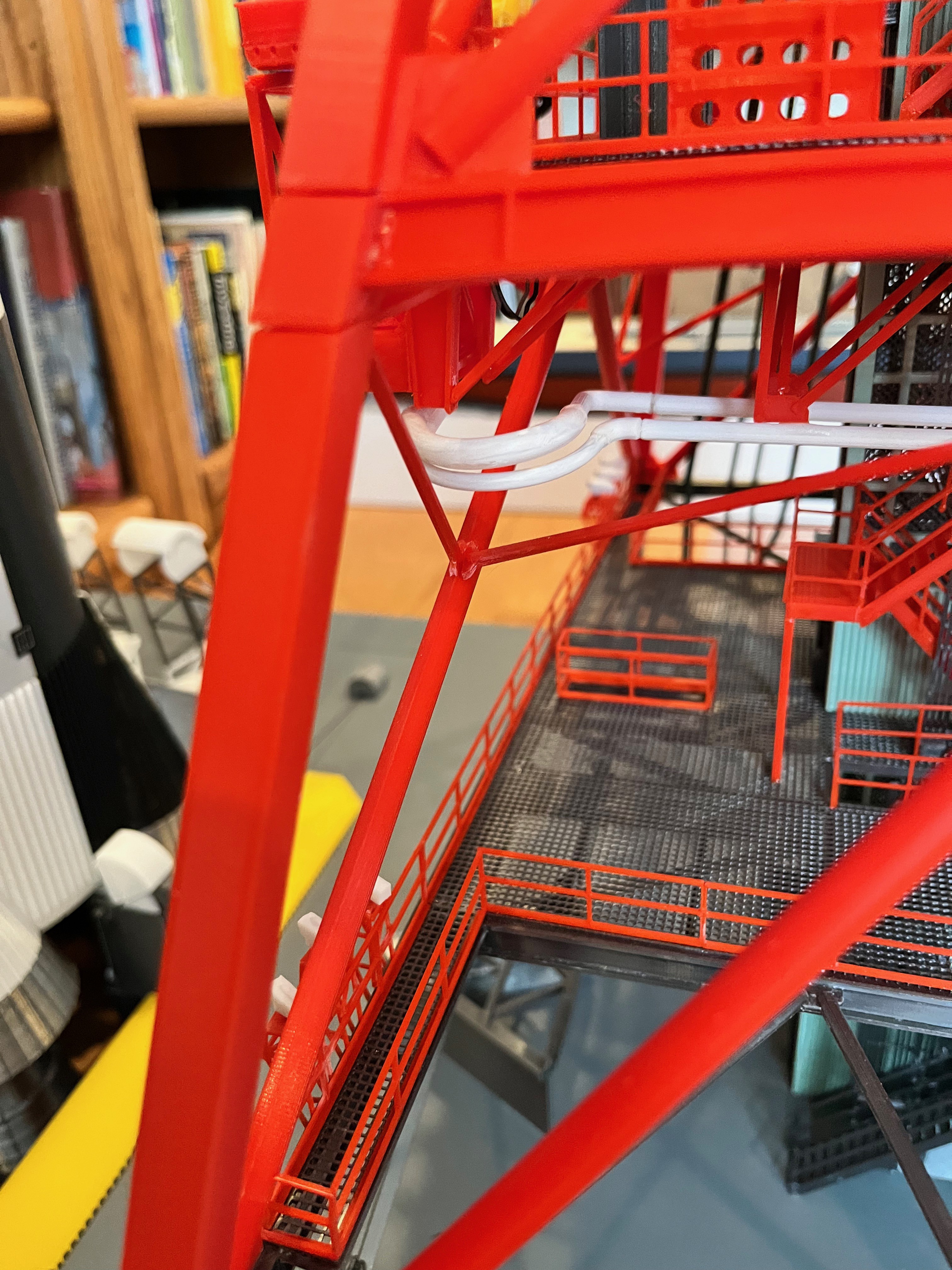
The pipes that feed the LOX are not per the MicroArtwork. Those pipes didn't make sense when you look at the pipe bends both extended and retracted. The larger of the two vinyl tubes is much less pliable than the skinny one. Taking all that into account, this is my solution. You can see the tubes both extended and retracted.
Swing Arm #1 Complete: The walkway is in and this portion of the model is now published. I was going to paint parts of the camera black but forgot to. Notice that the stair treads are not grating. These parts would have been too small so I made the treads solid (just a shorter version of the main stairs). Since swing arm #1 was 84 parts and rather complex, the other arms will also be their own models and therefore will be tackled as they come up.
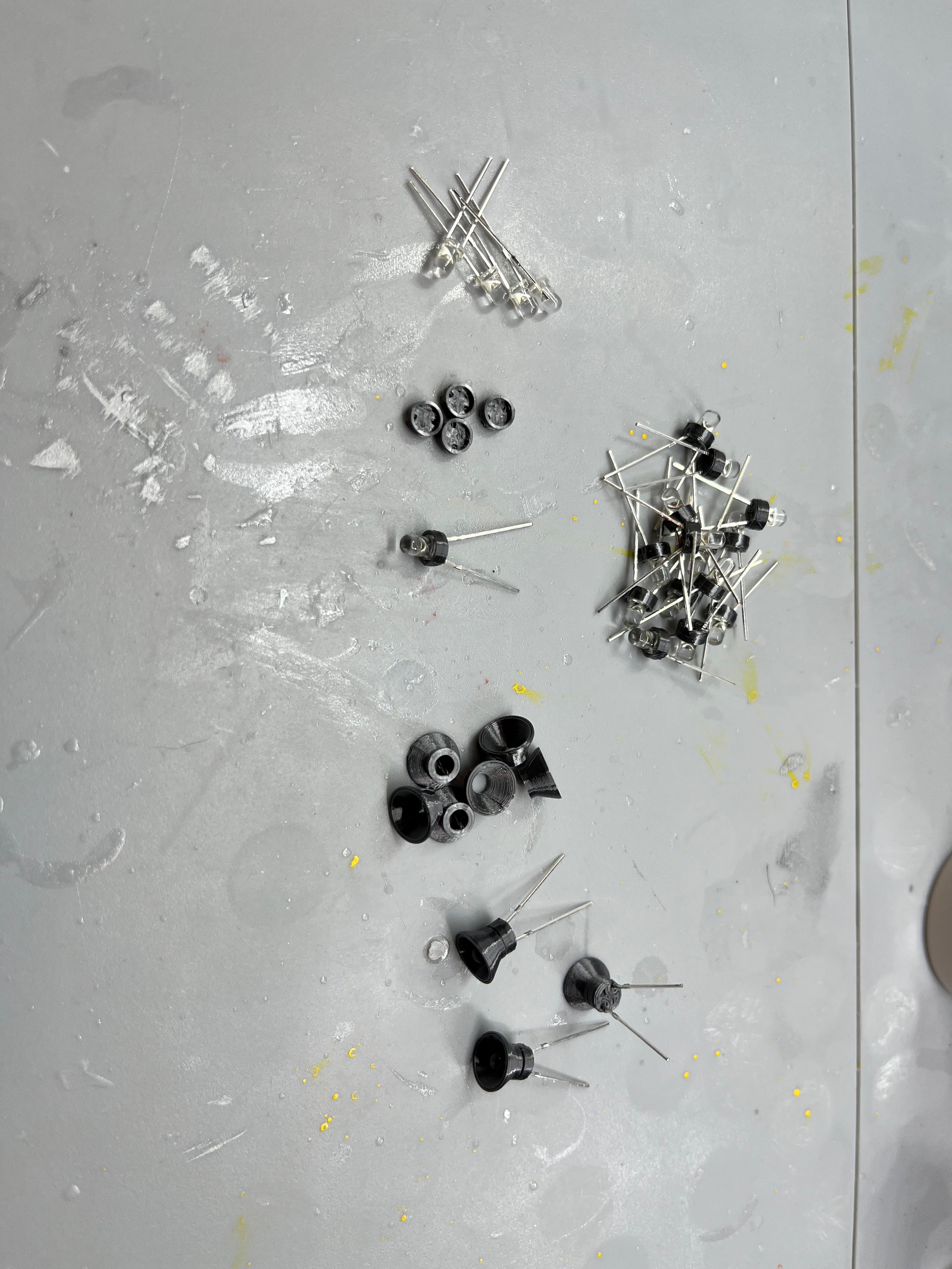
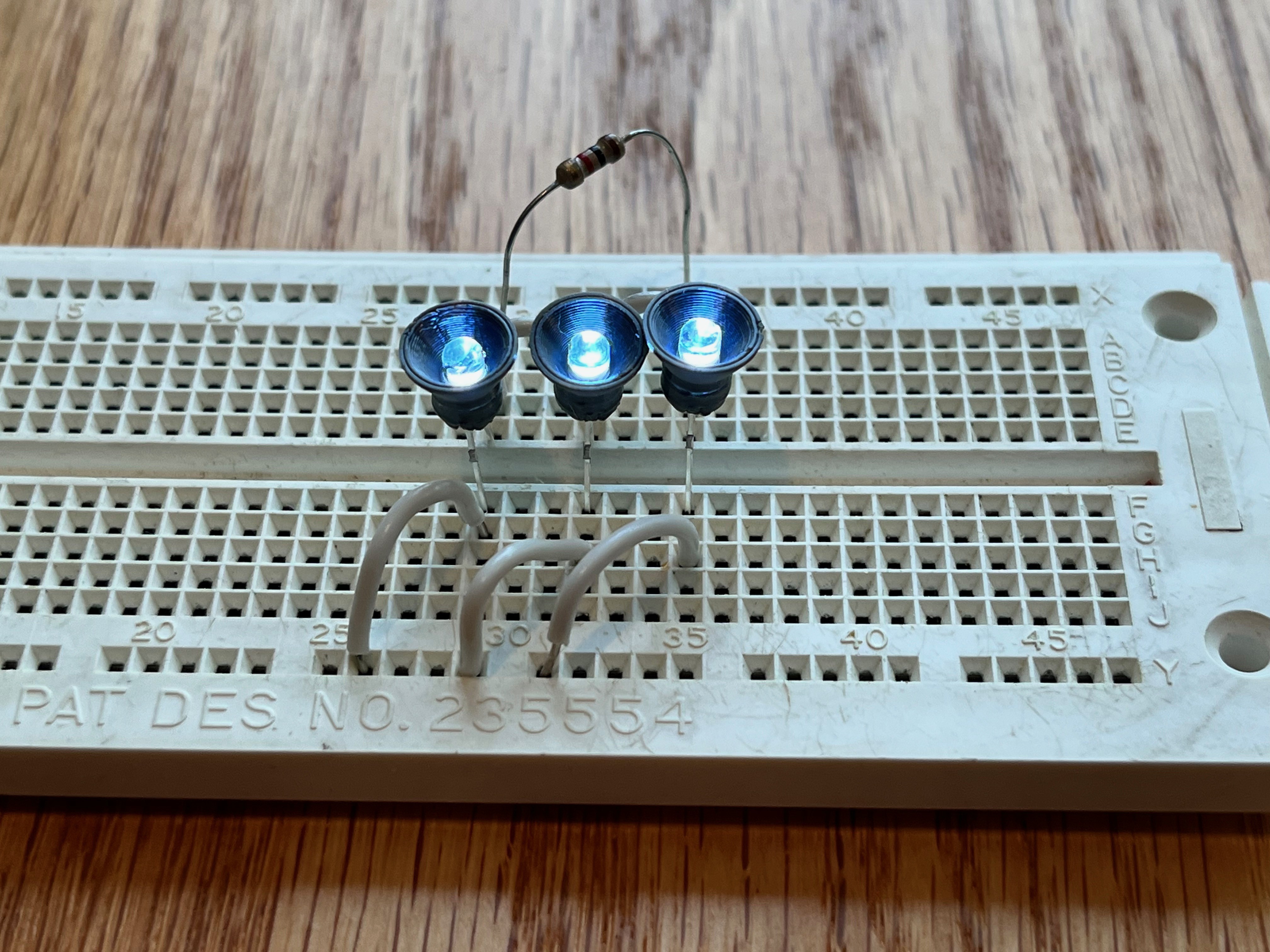
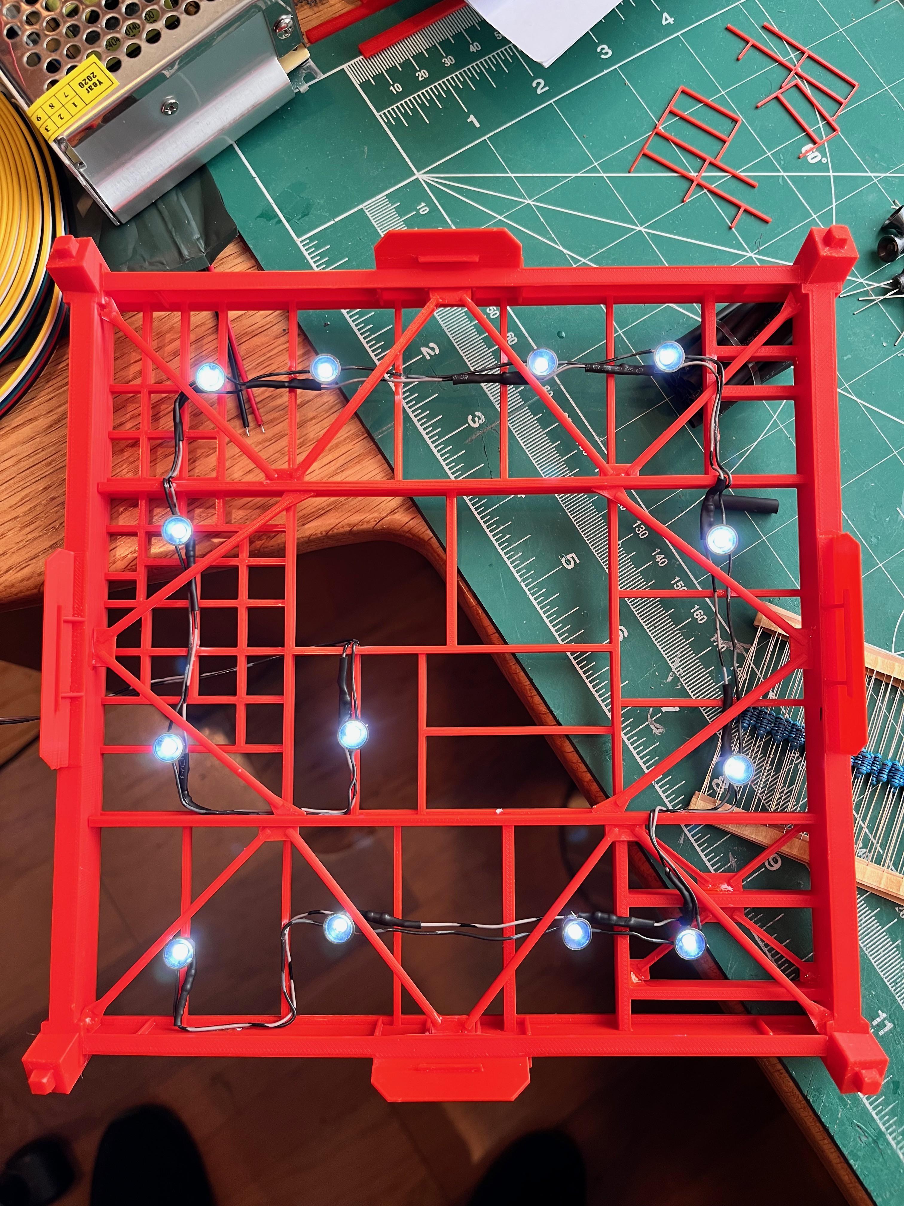
Lights: There are almost 250 lights on LUT, not including the swing arms. To get the correct scale look, the proper number of lights, fairly dim will be the best. For this I had a bag of 3mm white LEDs from a previous project. I ordered another 200, $7/100 from Amazon. To direct light downward and make them look good I created two pieces, the shade and a cap to cover the top.
I am always looking ahead 4 or 5 steps. Is there something I need to be considering now that makes things easier later on? So far I have done nothing with the swing arms. These are models unto themselves. Fortunately the main structural portions are common, the first and second elements. Despite this, some of the arms are very complex. I want this model to be as detailed as possible given the limits of scale, therefore the swing arms should articulate, both swing away and extend/contract. There should be working lights and accurate piping and cabling. The cabling should be easy, various size wires. The piping will be more difficult as there are flexible sections. The best material for this seems to be vinyl tubing. There are various small sizes available; 1/8", 3/16" and 1/4" OD. As long as these take paint everything should work. There is a good set of on-line pictures at turbosquid that show various angles and the ends extended and contracted. So far I have combed through these pictures and the various technical drawings out there to update the spreadsheet and sketched in an initial set of parts that may be required. Usually this first quick pass results in less parts than are required for the finished model. As a result of this effort, the total parts count is now up to 4,000. Bottom line? The arms attach to the support and locking columns that can be added on after the tower is built as will the external pipes that run up the tower. The one thing that is affected are the railings because there are walkways that extend out and around one of the legs to access the arms. I expect these railings to be added on after the tower is built due to their delicate nature.
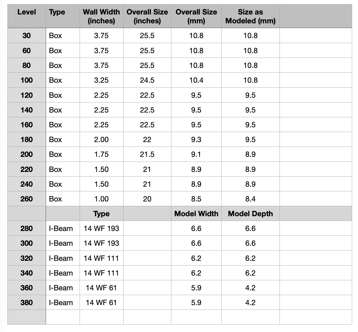
To glue or not to glue, that is the question. Actually the question is how much of the tower to glue together. The launcher base is large and heavy. I should definitely be a separate piece. As far as the tower goes, having each floor separate seems to be too much. At this point I think if I glue together levels 30/60/80 that would be a good chunk of the tower that can be easily managed and manipulated. The Support and Locking columns split at that point. From there I plan to glue the tower in 3 section chunks. That would be 100/120/140, 160/180/200, 220/240/260, 280/300/320 and 340/360/380 with the crane probably being separate. This means I need to have connectors at every break for the six wires running up through the elevator shaft. I plan to have the swing arms removable as well. The lower hinge can be glued to the support columns with the upper hinge being split into two pieces that dovetail together with the base glued to the columns. The swing arms will need a two wire connection for their lights.
I have completed a restructuring/renaming effort to make more sense of the parts. The farscape1 model lists parts with a prefix of say "L60". Are these parts above or below level 60? Same thing with the Aviator67 parts. It appears the Aviator67 parts designation mean the parts sit on or above level 60. For the farscape1 parts it appears the parts are on or below level 60. This has been confusing as I am printing and assembling parts.
What I have done is denote levels as say "Level 60-80" which means the parts that sit between level 60 and level 80. I have not renamed the existing parts so the "Level 80" structure parts sit between level 60 and level 80 (the level 80 floor beams and legs that support level 80). It also contains the Aviator67 parts that sit on top of level 60.
I hope this makes sense.
I have built and dry fitted the elevator shaft and stairs up to level 80. This includes piping that runs up through the stairs as well as the elevator pipes that Aviator67 produced. I have now decided to publish these files that go all the way up, however I have not verified anything above level 80, but much of it is repeated. Near the top I will have to add some more files related to the stairs.
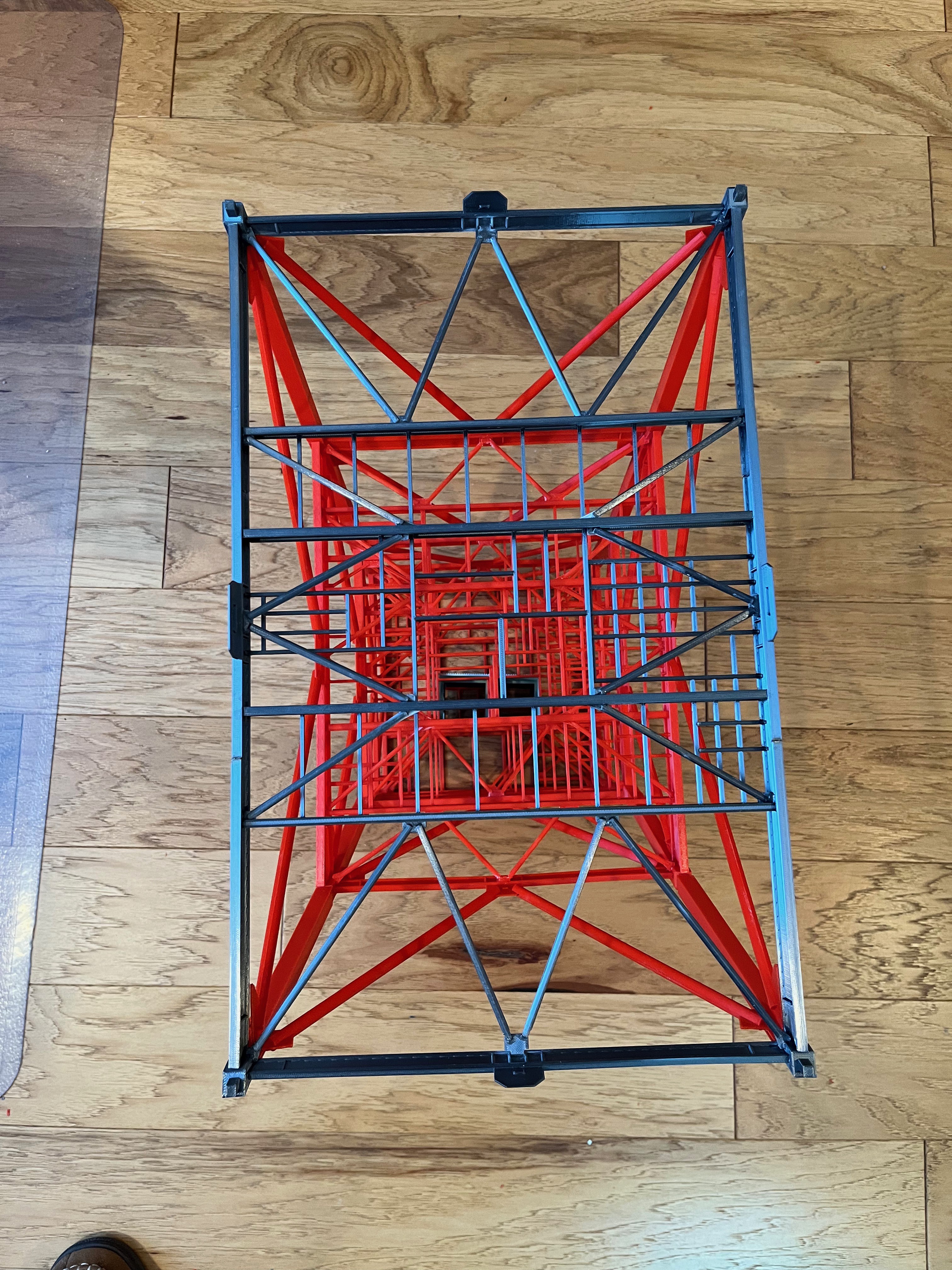
And here is the level 0-30 cable trays. I am happy the way this difficult section turned out. You can see the horizontal cable tray hanging from the ceiling. The little tray hangers worked well. After gluing them on I used a sprue cutter to nip off the ends flush with level 30 floor.
There are still lower cross braces to hold the lower part that extends below level 60 that I still need to design. The only pieces that are not exactly correct per the drawings is the width of the vertical I-beam's webbing which I made thicker for strength and the L-brackets which I made square, again for strength.
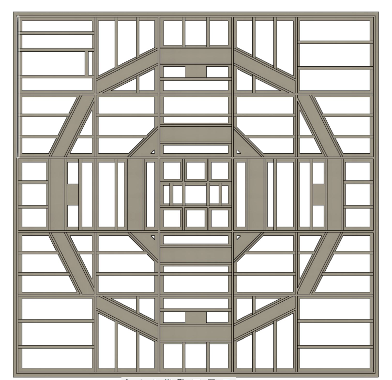
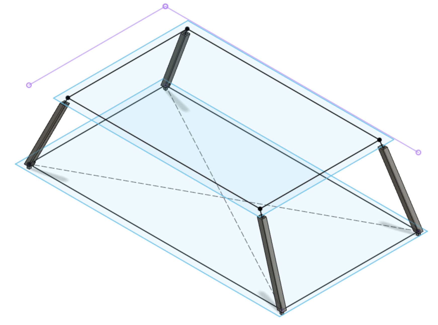
How to slice up the tower? I definitely want working arms that are removable. Not yet sure if that's possible. I am fully committed to the model having removable sections, although you can certainly glue it all together. Beyond that I was initially thinking 3 levels at a time. Now that I am designing the support column I realize that if I section the support column into 3 level sections it will require parts that are over 304mm long. While I can print those on my larger printer, I have been unhappy with that printer and have been using the Prusa printer for everything. It has a print plate of 210 x 210 with a diagonal of 297. There is no way to print sections that long on the Prusa. What if I go with two sections at a time? I am a visual person so I drew up a diagram to understand how the arms come into play. Some of the arms are packed so close together, some of the support columns need to be split mid level so both hinges are attached to one printed section. It turns out the best way to split the support column is 2.5 levels per section and the removable sections just so happen to alternate between two and three floors at a time. This is my plan and I'm sticking to it. At least until I find a flaw with it, then it will be time to pivot...
And once the sun went down I took pictures of the first floor section with the lights off and on. The 1k ohm resistors seem to be just about right.
The level 60 floor is now glued to level 30. I added the 6" bracing that holds the long 16" floor brace in place. Like level 30, I waited until the floor and bracing were on since the inner braces are at compound angles. It was easier to simply measure and then make the parts. Those are now out on Printables. The next level of cable trays are also glued on. Once I finish up to level 80 I will publish the cable trays. There are a lot of unique parts and I have been correcting some errors. In the first picture you can just see two wires sticking out where Swing Arm #1.
I am complete with the internal bling on Level 60. The LOX valves (thanks to Aviator67) are in. The mounting legs had to be trimmed a little to get the pipes to fit between the hand rails. There are new parts to get the two pipes across the space over towards Swing Arm 1.
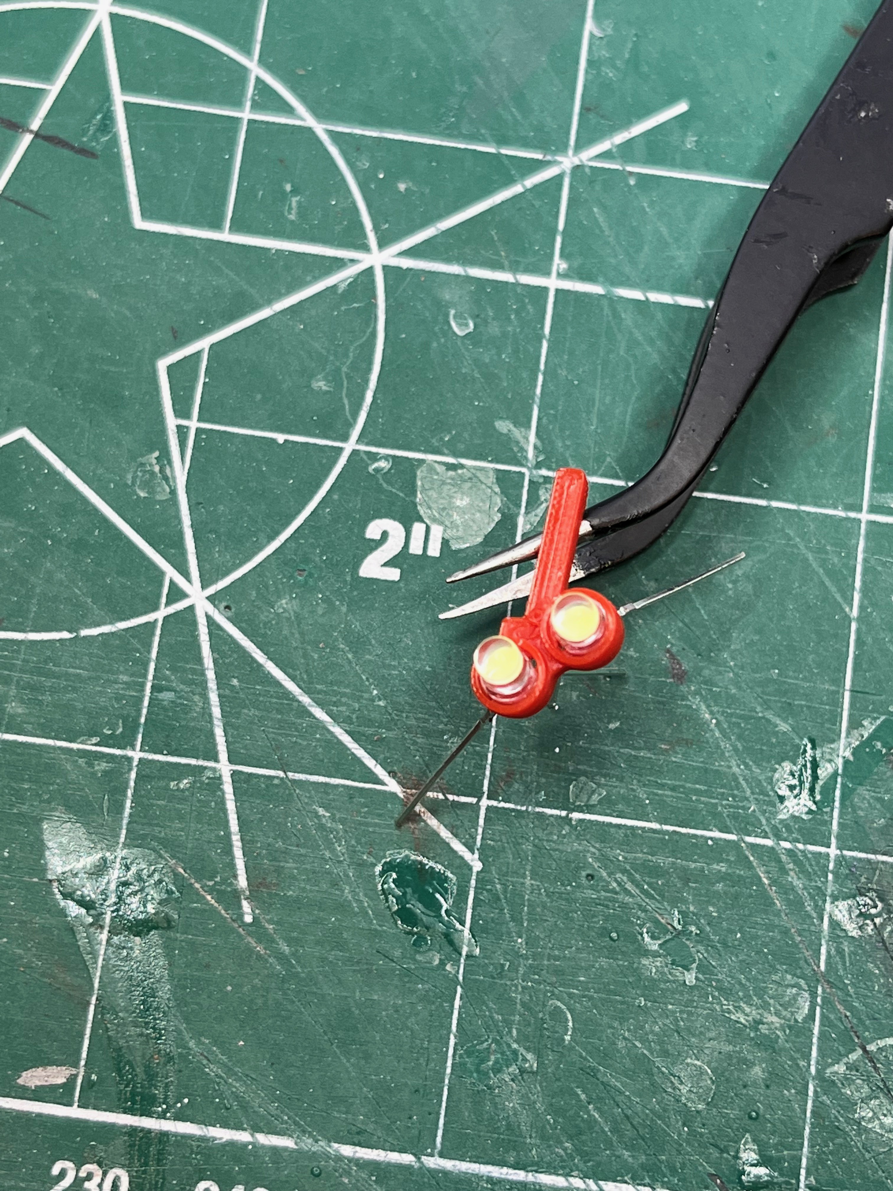
Here is a test print of a holder for the pair of flashing lights based on the previous light cap. I don't have any red 3mm LEDs so I am testing with white. The idea would be to solder the inner two negative leads together and then solder three wires that would go around the leg, under the little arm that somewhat shields the wires and provides a better glue surface. The resistors would be located somewhere else, below the floor grate or in the elevator shaft. I will need to use a really fine soldering tip.
For the pipes going up the side I am going to break with convention. For some reason most modelers shy away from supports like it's some kind of curse. After making the two sections of 18" LH2 pipe that go up the first section of the tower I split them and sliced them and then sliced the whole parts. The whole parts with supports take 18% less filament and 13% less time to print. Why? Because the split pieces have solid outside layers that go through the middle of the part. The whole parts only contain infill. In my opinion the whole parts look better because there in no seam down the middle or any chance for mis-alignment and there is less assembly time. I'm going with whole pipe parts. If you ascribe to the no support ideals, then by all means, feel free to slice the parts in half.
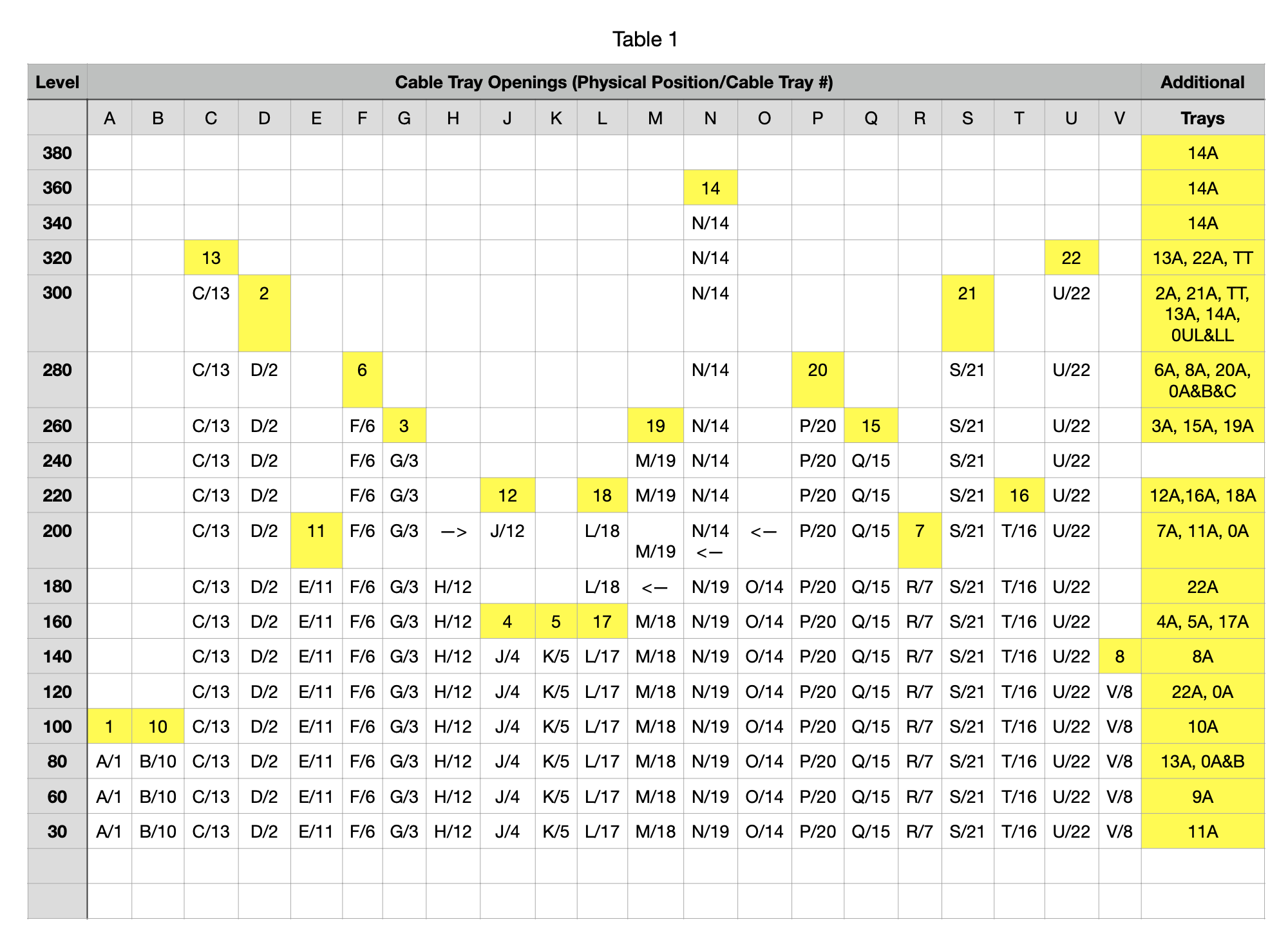
Side 3 LOX/LH2 Expansion Joints Decoded: I could not make sense of the Aviator67 parts. I took a look at 75M-05753_35 and 75M-05868_09 in the Cato Library. You can see in the attached spreadsheet (out on Printables as a CSV file when I publish the Pipes) that I listed each joint type by level, the number of required joints by level, the actual pipe size and the model pipe size. I then listed all the Aviator67 parts that I could find along with the opening size for the pipe. The pipe designators did not match up to the documents I am looking at, however the MicroArtwork and TurboSquid almost match up. There is one missing joint in TurboSquid. I really like the look of the Aviator67 parts and really don't want to re-create these. Some are close enough to work as-is while others are close enough that I can simply scale them. To avoid confusion I am going to rename all the parts to match the documentation. The documentation also has lengths of pipe between levels and/or joints. I will split the pipes between joints and between tower sections so as to minimize the number of parts and have the parts fit a 210x210 printer. The parts will then be listed by level or if they span levels, listed with the first level they span.
The warning lights at level 30 are on. I used a pair of red LEDs with 470 ohm resistors. Fortunately I decided to build the tower as removable sections so I was able to remove the first section, turn it over and route the new wires.
You can see in the above picture a hint of the LH2 and LOX pipes on Side 3. And below is a picture of Side 3 with the LH2 pipes and hydraulic pipes complete. Unfortunately the expansion joints from Aviator67 for some reason were made with two different hole diameters. These hole diameters need to be the same. I took the largest EJ file, combined the two halves, sleeved the larger hole to match the smaller hole and then spit it in half. The other smaller EJs were then scaled to size. The LOX pipes still need to be added to the Launcher. Then it's on to Side 2.
I have started working on the pipes for Side 2. Aviator67 has very nice expansion joints for the ECS pipes. Unfortunately there is an error in those expansion joints. Fortunately the fix is easy. There are 10 pipes at the lower levels labeled E1/E2/E3/E11/E9/E10/E4/E5/E6/E7 going left to right. There are three sizes I will call small, medium and large. The pipe sizes, left to right are S/M/L/M/M/M/M/L/M/M. The Aviator67 expansion joints have E4 as a small pipe. The Micro-Artwork and TurboSquid both agree with the original documents that this pipe should be medium. I simply edited the expansion joint STL file, removing the small part and copying in a medium part. Problem solved. The pipes will all be modified to have connection joints and to be solid. I will also make the lowest section of these pipes printable as grey per the pictures. There will also be non-glued connections where the tower sections meet.
Part of splitting the tower into sections is deciding what to include in the lower section and what to include in the upper section. Here I chose to glue to the level 80 floor the equipment, railings and elevator shaft. The rest will hang from floor 100 to include the stairs and cable trays. For some reason the added equipment parts was missing two of the boxes to the left. I simply created boxes of the correct size and glued them on. The other thing you will notice is that I have use the sprue cutters to nip off the top of the elevator. Because the floor beams get smaller as you go up the tower, the elevator shafts should be unique per level. I decided to make one elevator shaft from level 80 up. For these lower levels the I-beams are larger so the elevator shaft needs to be shorted a few millimeters. The good thing is that the tops of the elevators are not really visible.
The water pipes are designed, printed, red bands painted and glued in for section #1 of the tower. I did not design in pipe stand-offs because these are small, light and airy. Instead I simply glued them to the I-beams. The first of the ECS pipes are printing. I need to go see if they are complete...
While waiting for parts to print I decided to decode the Aviator67 parts list. This includes getting the color correct in the spreadsheet and account for every part, including missing parts that I want to print. This involved comparing the equipment layout files against the MicroArtwork and Turbosquid files. I started at the bottom and worked up, just like the model is being built. There seemed to be missing files that I later found at higher levels. Sometimes parts are duplicated and in other cases you have to find them at higher levels. Fortunately the equipment parts are numbered, allowing for a search. My spreadsheet has been updated to reflect this effort. I also added the parts for the Amphioux Saturn V model to get a good count of all printed parts to compare against the farscape1 model. The farscape1 model has 2056 parts. Mine is up over 5000 parts and counting.
One thing I considered was modeling the deluge pipes on Side 1 of the tower, but decided not to until at level 260 I found upper and lower deluge pipes from aviator67. There appears to be a pair of these pipes for every swing arm, so about 9 sets. The aviator67 pipes seem to match fairly closely to the first set so I printed and added those. As you go up they are not the same and I will have to build unique parts for these. In the picture below you can just see the pipes. The upper pipe is at about the same level as the railing. The lower pipe is easier to see. I did not attempt to attach these to the water pipe on side 2.
The first section of the tower is now complete! This took quite a while due to all the CAD work that had to be completed. The next section should go much faster, only two levels and no swing arms. This will be a simple matter of verify and printing parts along with a little glue.
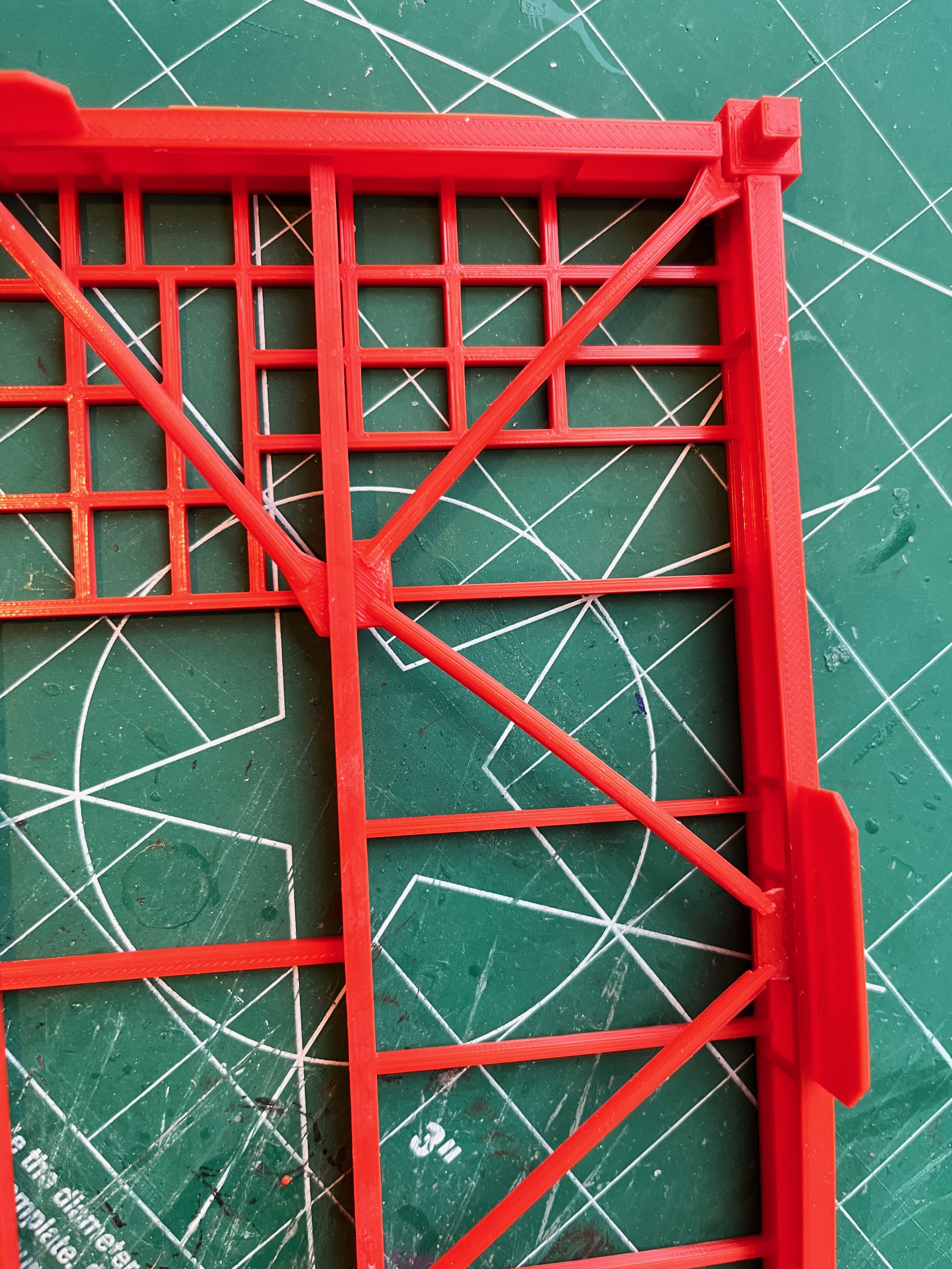
I love it when I can find parts that someone else designed, it saves me time and effort. Aviator67 produced a treasure trove of add-on parts for the farscape1 LUT. After printing and assembling the Level30 floor framing along with the cable tray template I realized the cable tray template is inaccurate. I displayed the Micro Artwork level 30 picture and enlarged it to size. Matching up the template to the picture it appears the portion in the bottom of the picture is very accurate, however the upper portion is too stretched out and conflicts with the framing. It looks like I will be re-creating these parts. I will also make the cross members of this "template" look more like what is shown in the Micro Artwork picture.
John, Thanks for the input. You have got me thinking. My initial plan was to go with the farscape1 portion of the model as is, with incorrectly sized elevator and all. Since I already have the Level 30 floor structure printed and glued up my plan was to cut out a few of the floor beams and draw up sections to fill in those holes. I have also drawn up the cable tray that hangs from the ceiling. This part is affected by both the incorrectly sized elevator and the beam locations. I only have one elevator section printed, so I have made the decision to redraw the elevator parts and the floor sections to make them correct. If you start with one mis-sized part, it seems to snowball and affects many other parts. Oh well, so much for thinking I was just going to print up and glue this portion of the model.
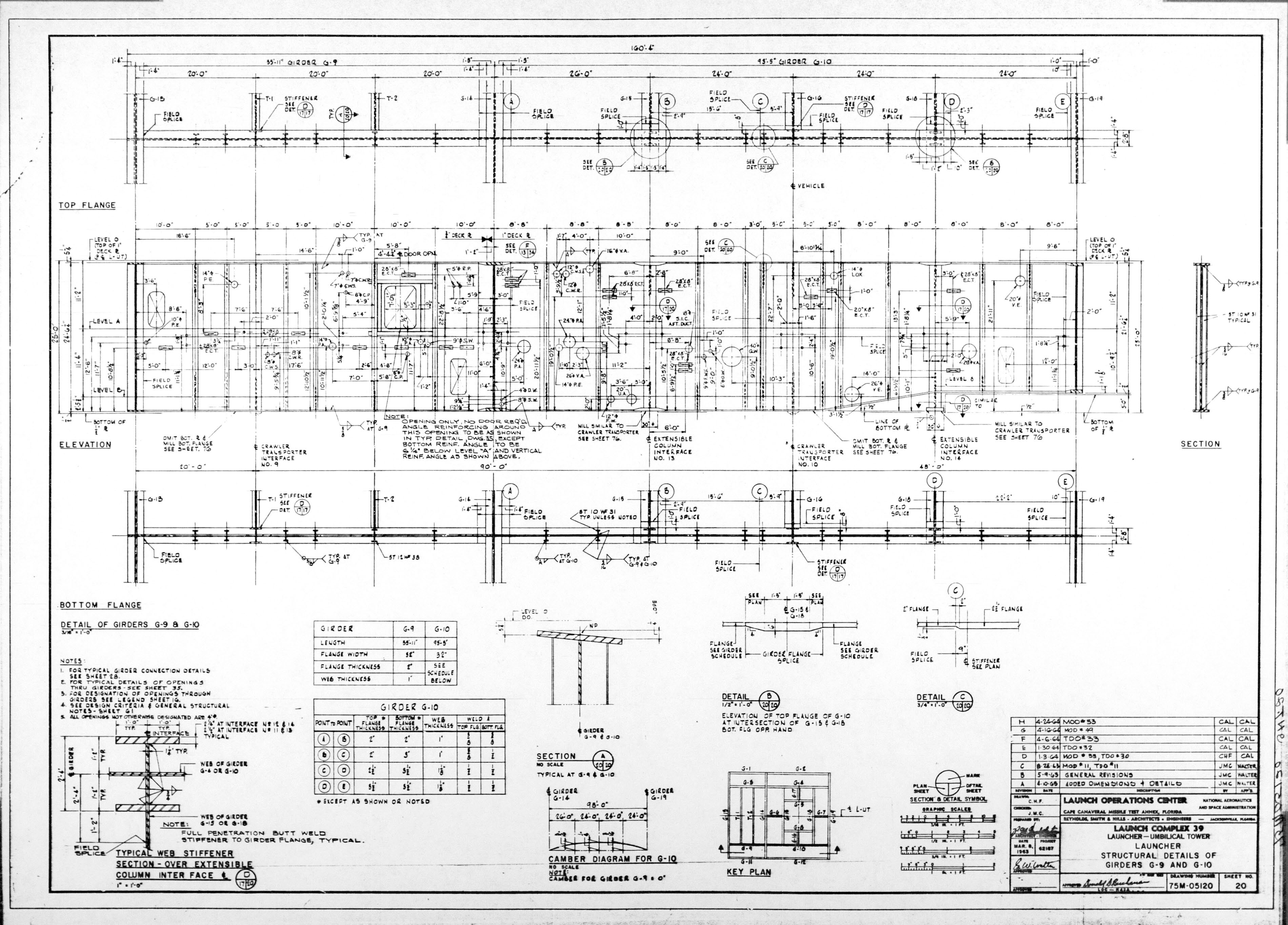
The level 30 platform should be 40' x 54'. The farscape1 platform is correct for the 40' dimension but off for the other dimension. The scaled dimensions are 250mm for farscape1 where it should be 274.32mm, off by almost 25mm, almost one inch!!! That will throw off the level 60 platform for sure. And as John says the gantry arms will all be too long as the entire tower needs to be shifted towards the Saturn V by over half an inch. I can see where this is going to take me awhile to redraw. I have started a new model page on Printables and will publish it once I get some parts drawn up.
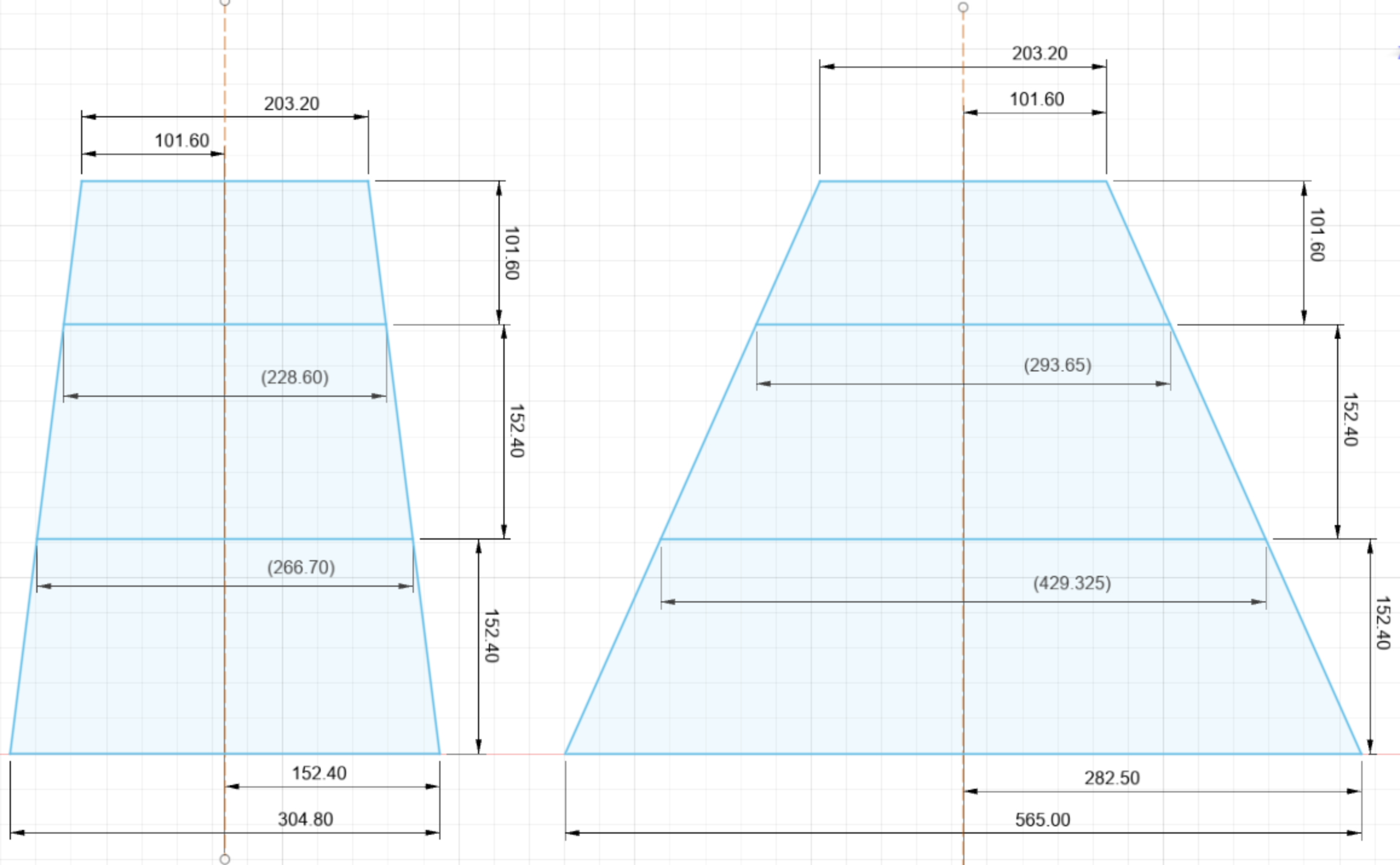
A first, rather small start. Here are the scale dimensions of the first three floors based on pages 54 and 55 of 75M-05120. I will base the new parts on these dimensions.
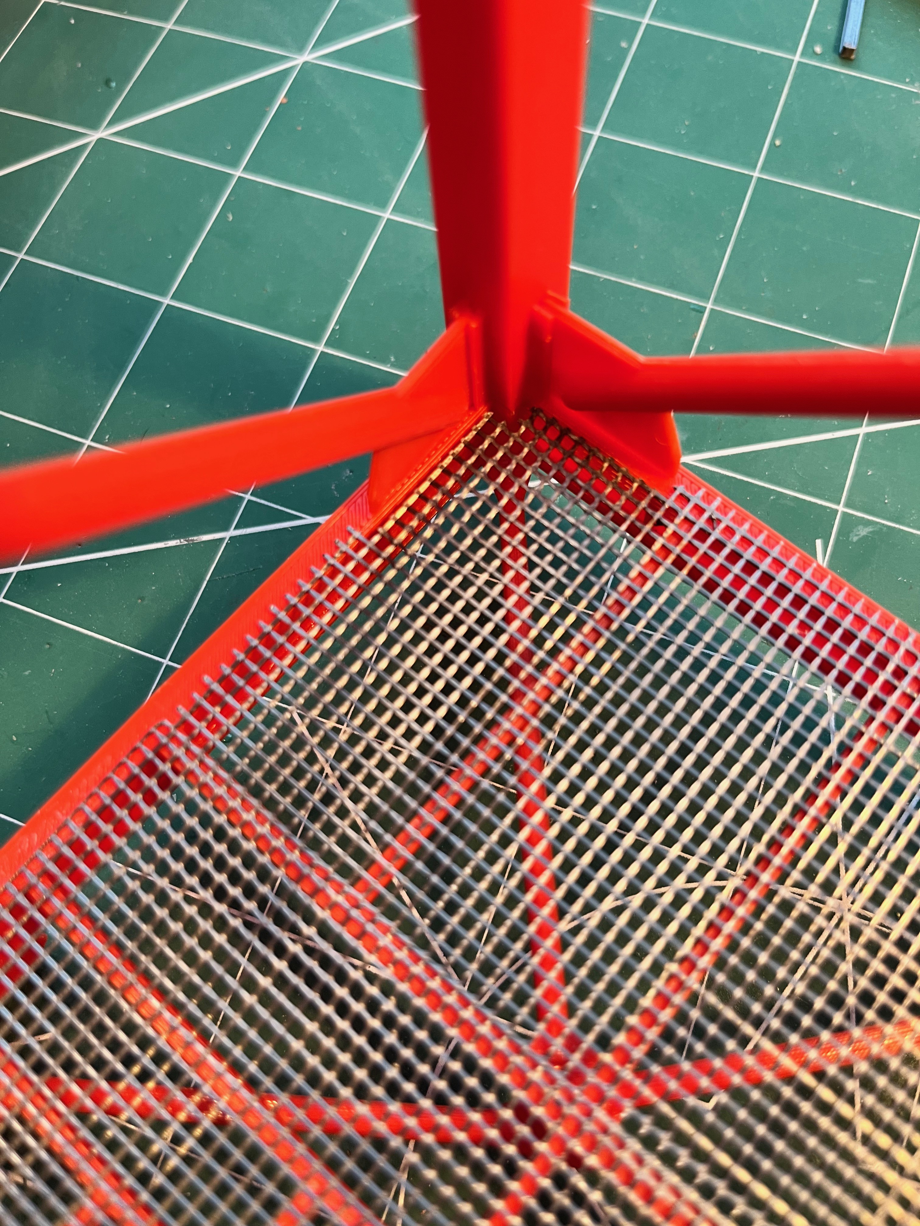
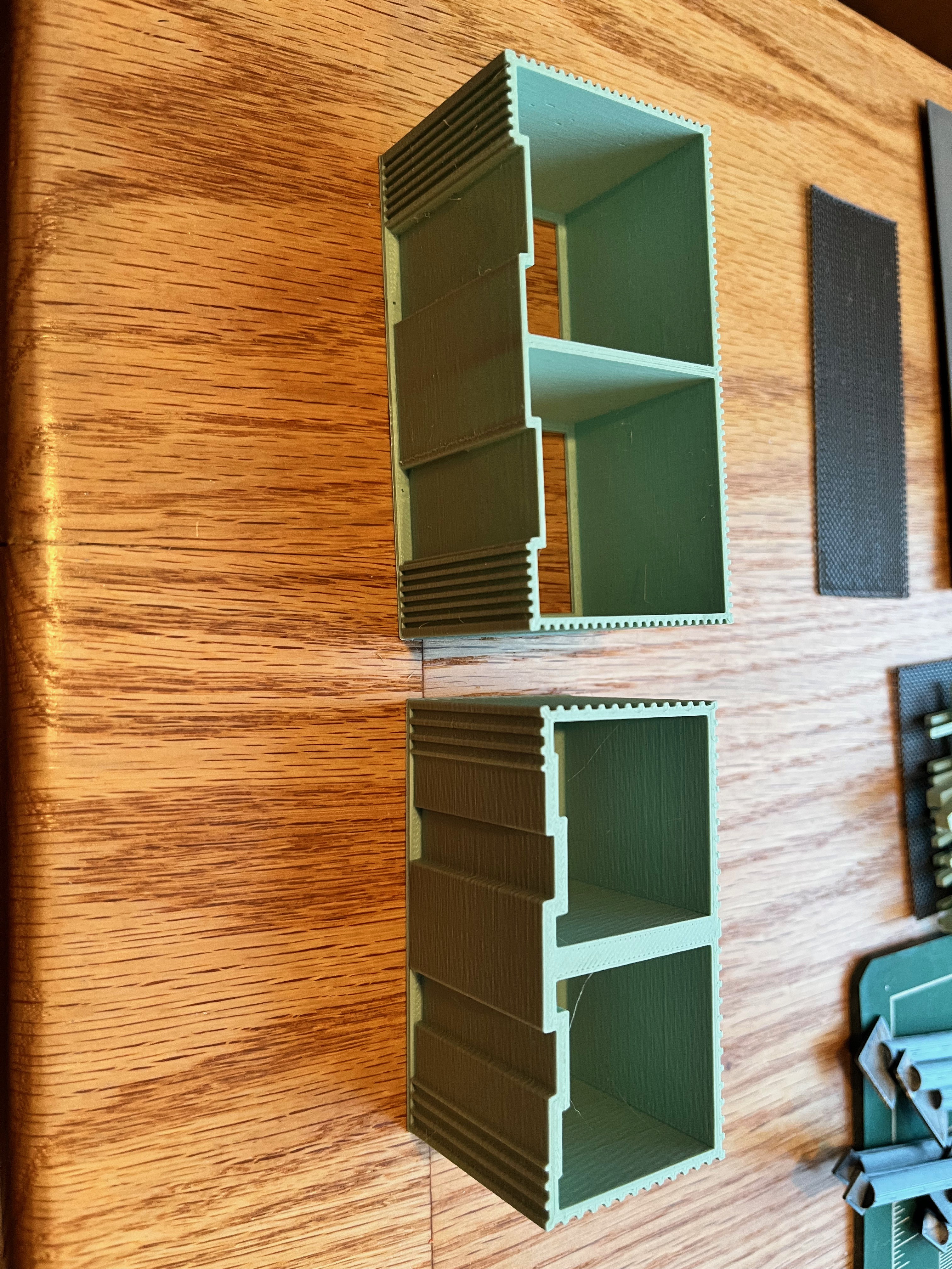
As I rebuild the tower I look at how to best draw and print pieces. Much of the tower is built using I-beams. If you print an I-beam as one piece you will need to add supports. Most people seem to create two pieces that are glued together. The farscape1 model slices the I-beams two ways. The floor supports divide the I-beams in the middle of the webbing. This is a rather visible portion of the beam that needs to be meticulously matched up in multiple directions. Since these I-beams are covered by flooring it is not too noticeable in the final model. The following picture shows a good joint and a not so good joint.
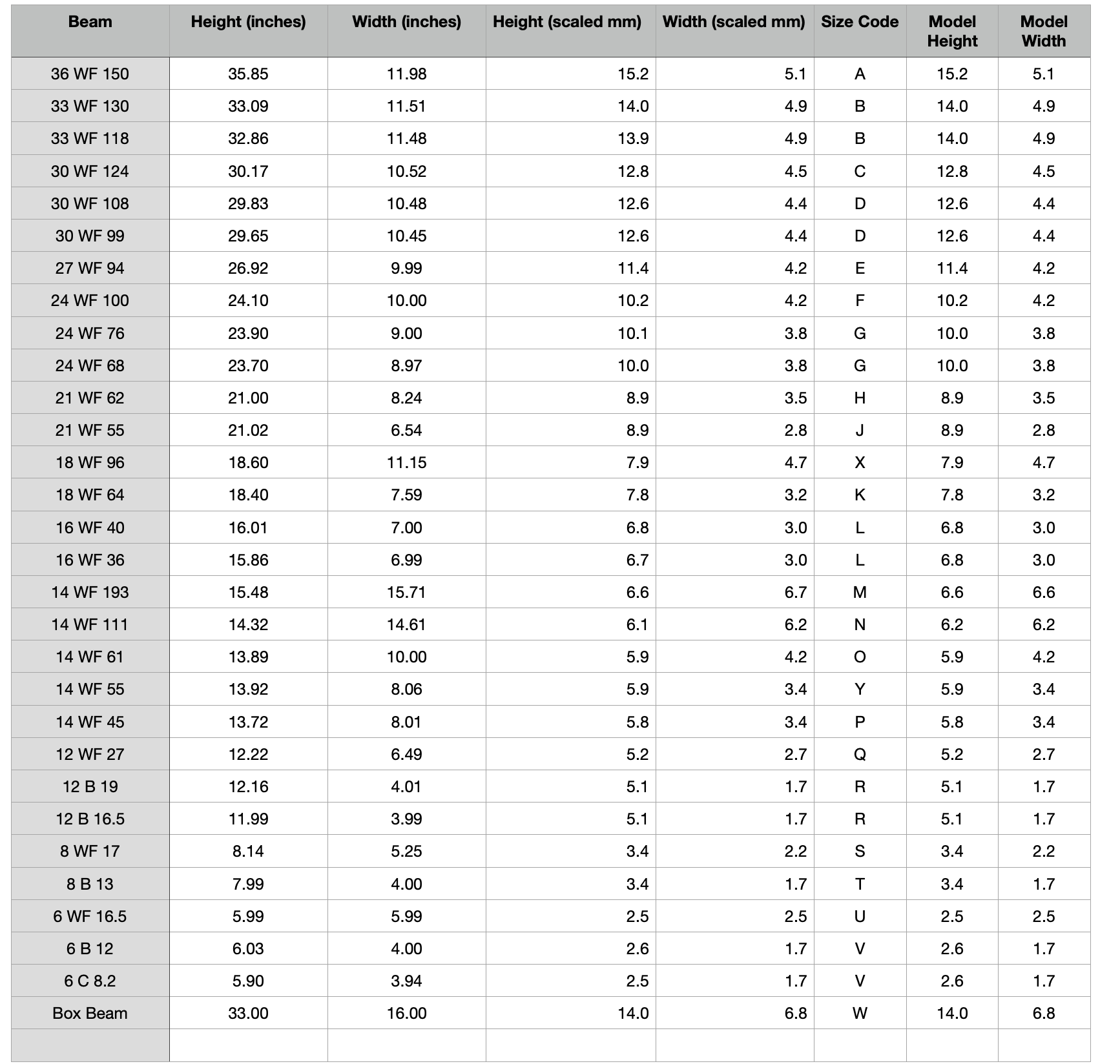
Not all I-beams are created equal. When building a model wooden ship the masts, spars and rigging get smaller as you go up in height. The same is true of the umbilical tower. The I-beams get smaller as you go up in height. This is a subtle but important detail to get the look of the tower correct and not have it look too top heavy. The following table contains the I-beam sizes I gleaned from 75M-05120. In the second table I translated each beam size into width and height for actual and 1:60 scale dimensions. At scale there are some sizes that are close enough that I combined some sizes. I decided to round up/down some sizes to something more printer friendly in some cases. When making the floor beam structure I also decided to make the internal beams that are covered by the floor grating rectangular versus "I" shaped, similar to what the farscape1 model does. All exterior or visible I-beams will be "I" shaped. Note: I made all web thicknesses 1mm even though the actual dimensions should be thiner, I wanted some added strength here. Same for the flange thickness, all are 1.4mm.
I now have the railing design completed. The first thing I noticed was what I am calling catwalks on Level 30 that extend out and have three cameras each. Aviator67 has the camera and camera mounts so I will use those as is.
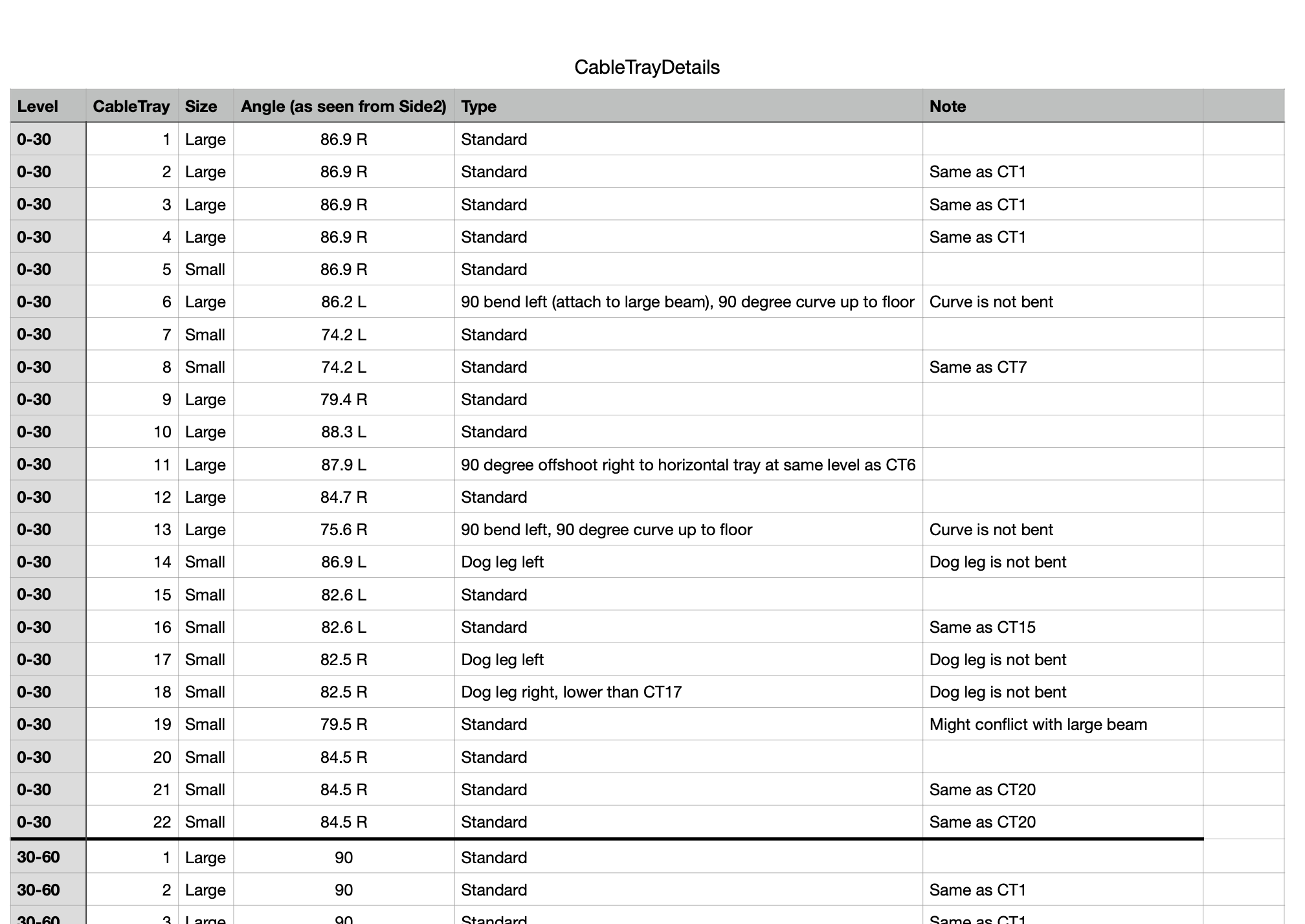
Yes, I have noticed many discrepancies. I'm guessing this may be due to modifications/additions that were made between missions. If I find a discrepancy, I am considering the 75M-05120 and 75M-05121 documents as the absolute truth. They win out over everything else. For the cable trays there are plenty of exact measurements. I do like the Micro-Artwork because it is easy to visualize the parts in three dimensions.
Level 0-30 Structure: The first level structure is complete!
Stairs: I have finally got the stairs the way I want them. Instead of trying to make the upper and lower stairs the same part I made two separate parts. It has to do with how they end. I also added the gray pipes and boxes that run up between the stairs for at least the next two levels.
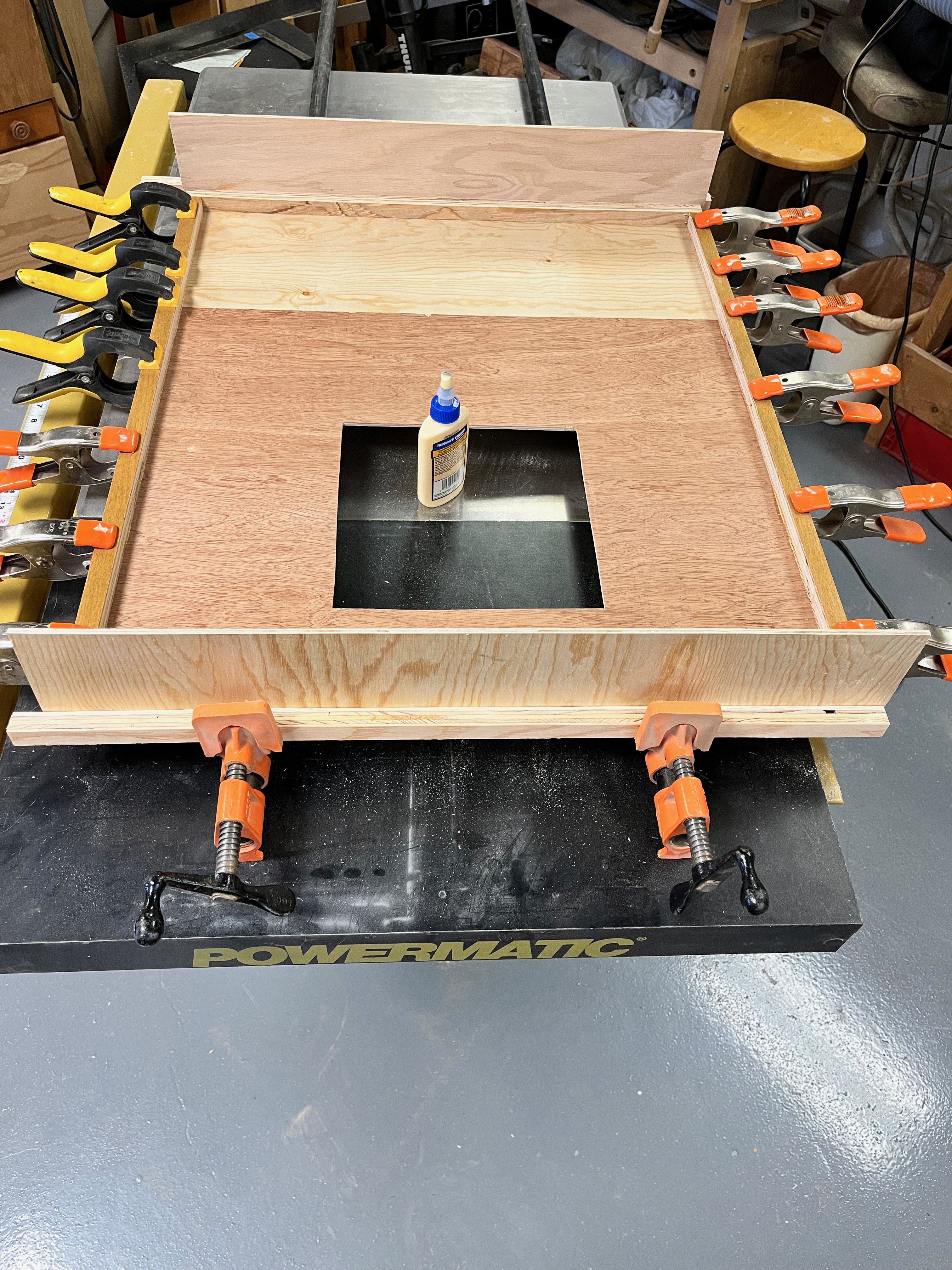
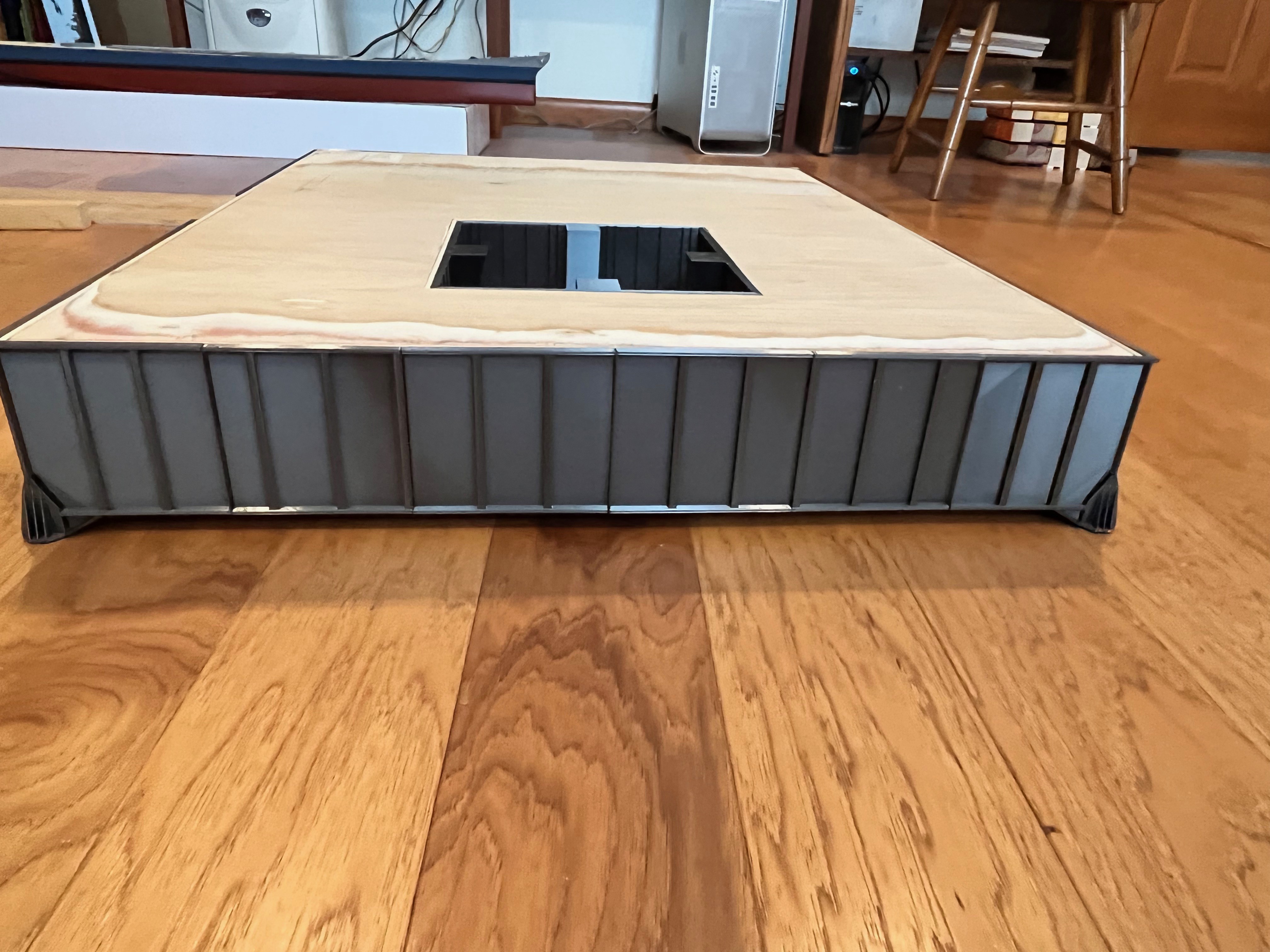
I am working on the Saturn V and realized it's looking a lot like fall out there so I wanted to complete the wooden box structure of the launcher while the temperature in the garage is perfect for wood working. I had plenty of scrap wood from other projects. You can say the box is 31" x 26 1/4", but it's hard to grasp just how big that is until you start to build it. The crawler is small by comparison.
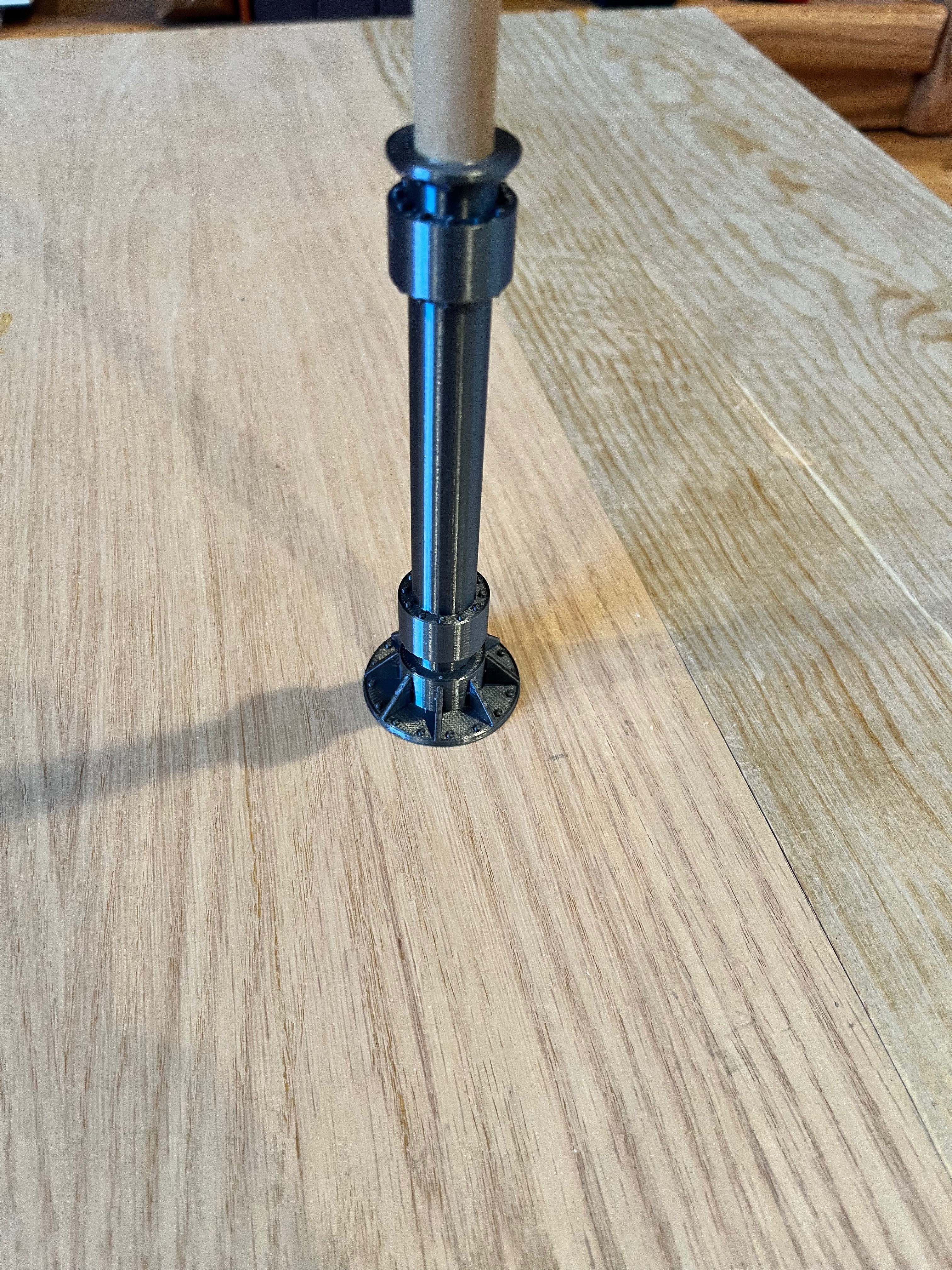
The box is fairly heavy and I want to be able to park the crawler underneath without putting all that weight on the crawler itself and be able to pull the crawler out occasionally. I went ahead and drew up the three pier types, but wanted added strength as these 6 piers will hold up all that weight and the plastic may snap if pushed on so I created a hole through the middle to insert a 1/2" wooden dowel. The dowels will go up into the box through holes and be epoxied in place. That should give plenty of strength. This is the type 3 pier.
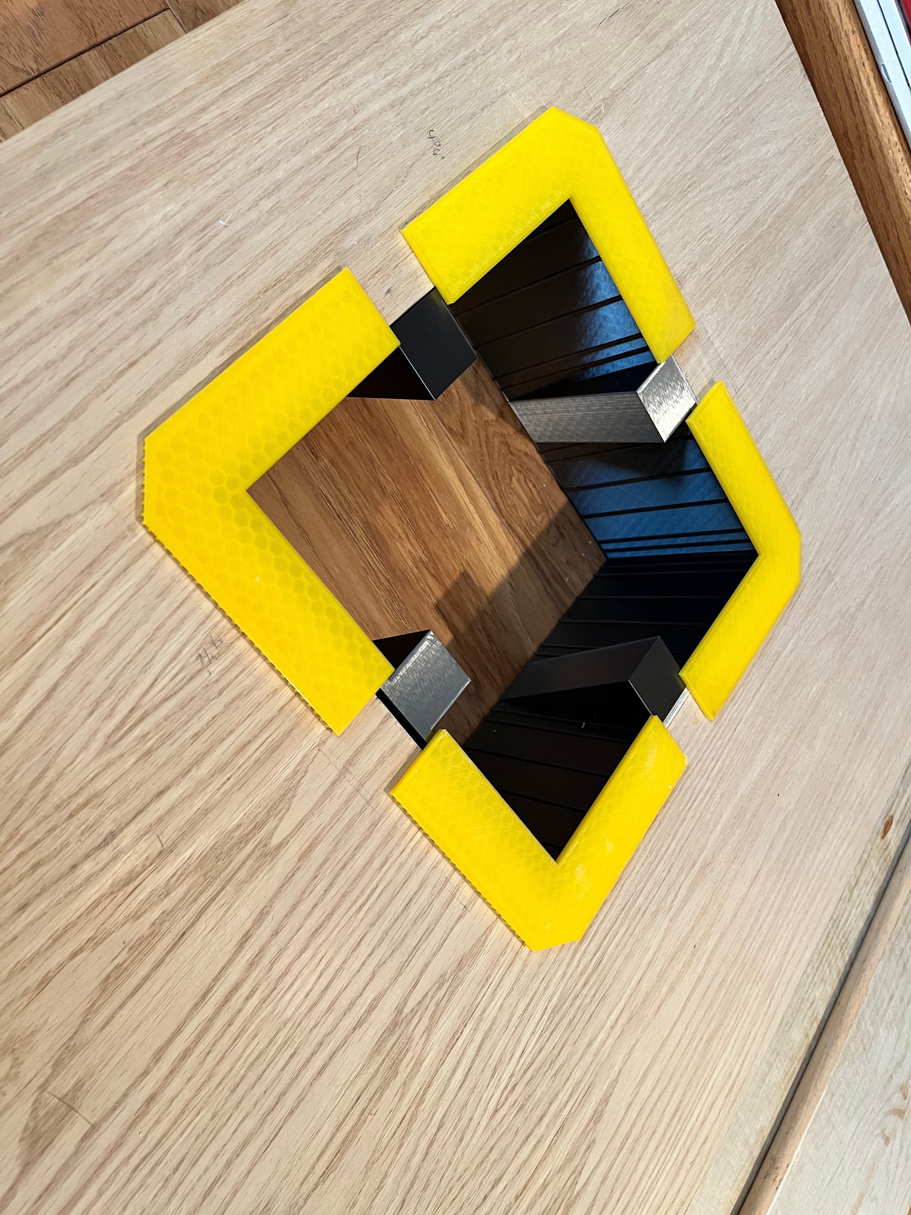
I have printed the four engine chamber walls and separate yellow engine warning plates. I like the color the yellow adds. I may reprint the warning plates as the yellow plastic is a bit too transparent.
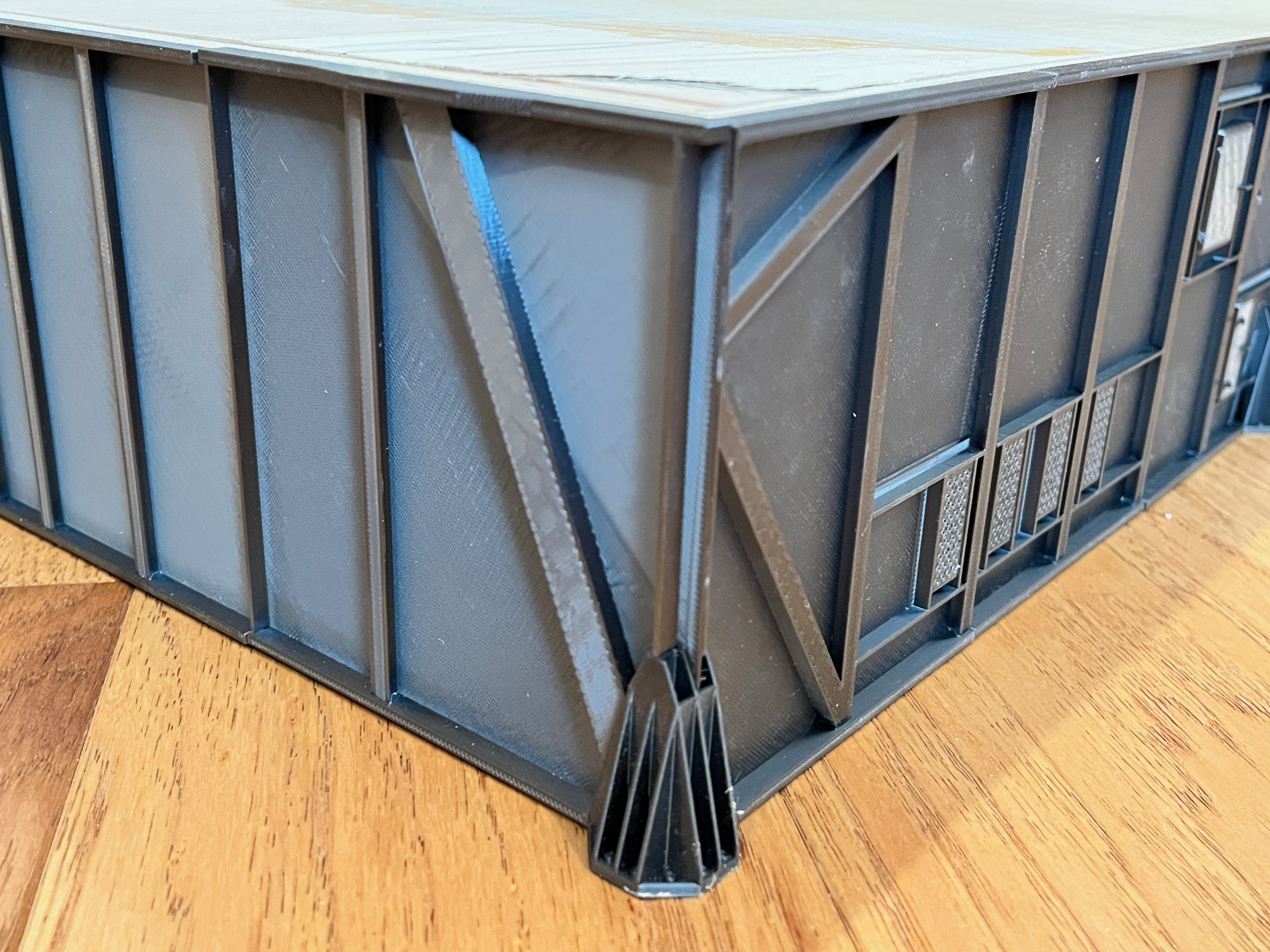
The most important part of the Launcher skins are the support interfaces where the piers attach. Six of these points have to support the entire model. At first I drew up one of the supports using the exact dimensions and printed it out only to realize that the 3/4" webbing scales down to something waaaay to thin. I decided to beef the webbing up to 1mm which is technically not to scale but is much stronger and still has a good look. You can also see I added a 1/4" hole up through the bottom. This is where a 1/4" wooden dowel will be inserted to pin the pier in place and add lateral strength. The corners of the box need to be chiseled out to fit the bottom plate so the launcher is flat on the bottom. This will also add more glue surfaces. Once these supports are epoxied in place the hole needs to be drilled out to remove the corner of the box. The 1/4" dowels can then be epoxied into place. I think this will give enough strength to support the model.
I went ahead and printed Farscape's tail service masts. They are accurate enough and operable. As I wait for parts to solve the deck issues I continue to work on the next pieces and I've started to print the second stage of the Saturn V. I'm also waiting for a second printer to arrive. The printer is definitely the long pole in this process.
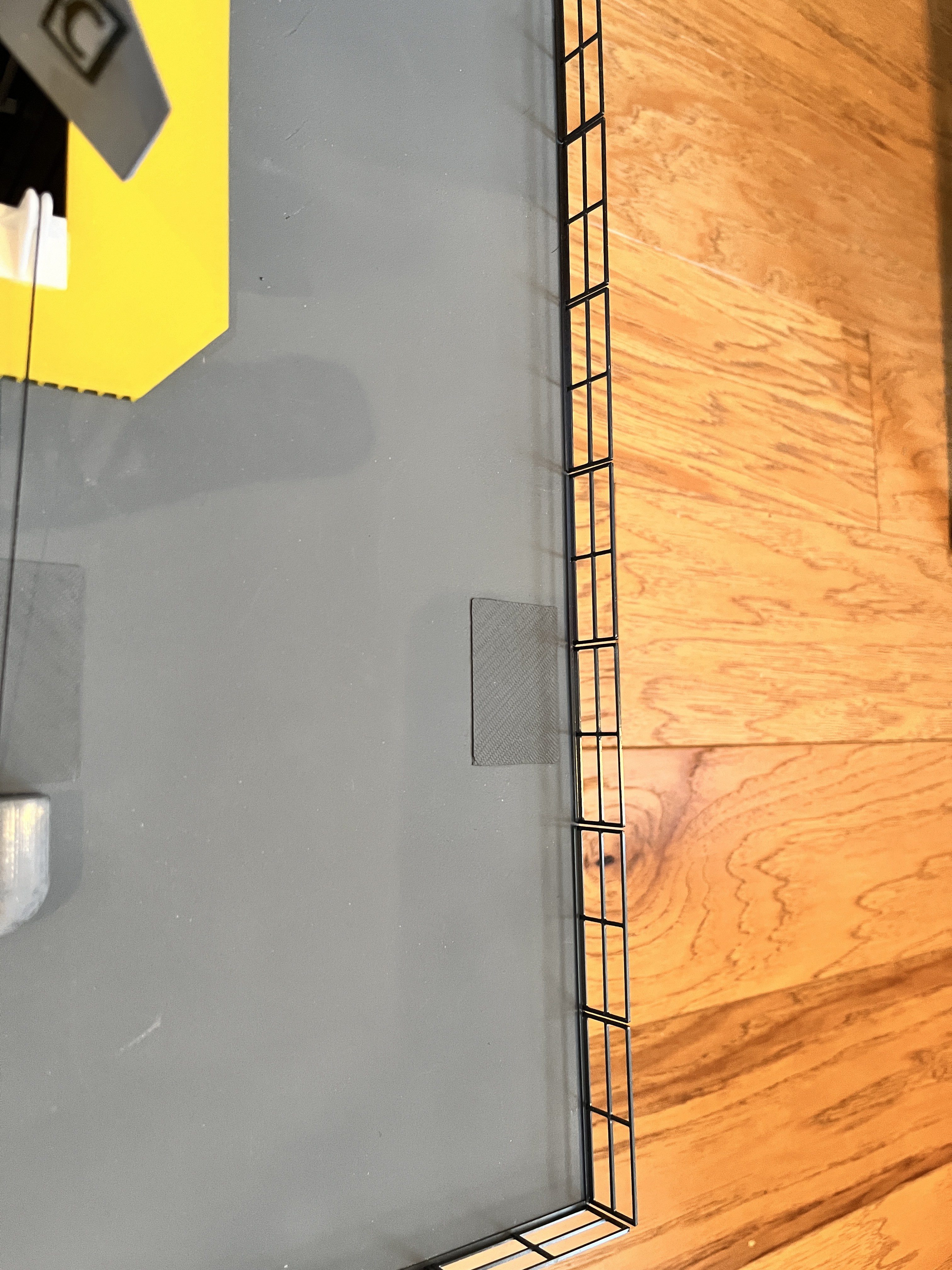
You will notice that there are little access plates on top of the model. Refer to 75M-05012 pages 12 and 13 for their placement.
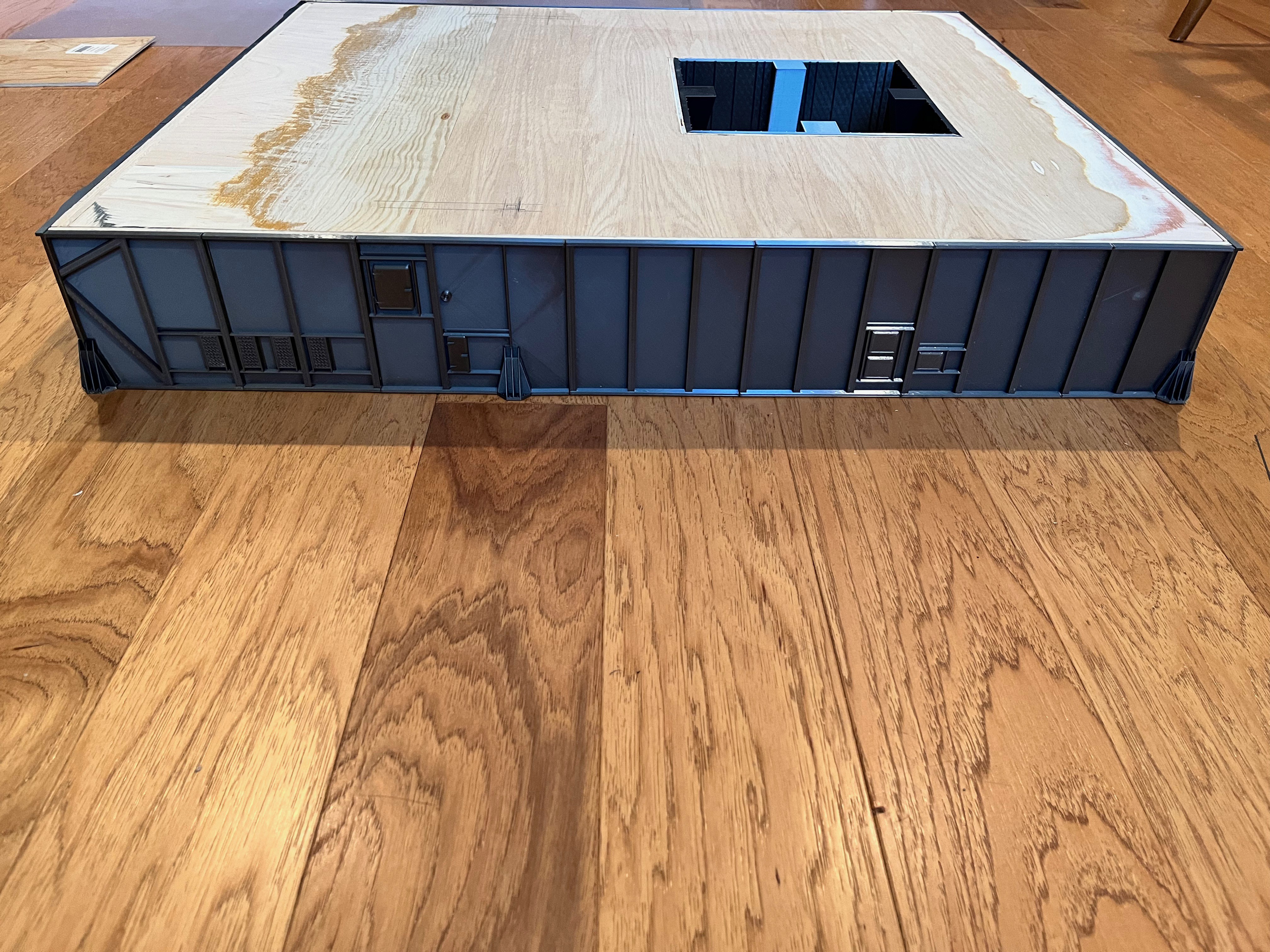
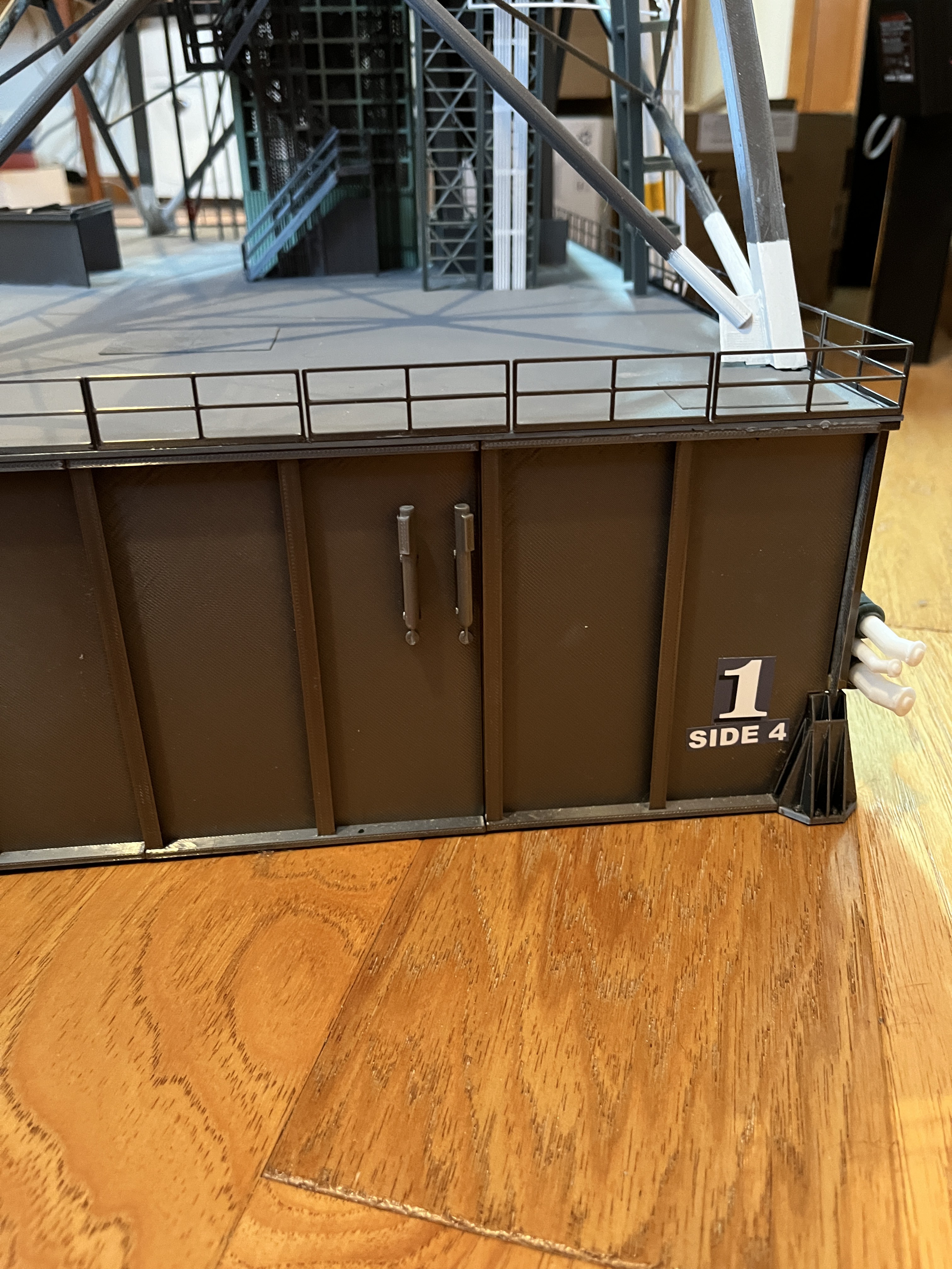
I have now added the decals to the sides. Notice on side 3 the top surface has a bulge where the tower legs come down.
I still need to add some additional piping on the sides, some decals on top and the perimeter railing.
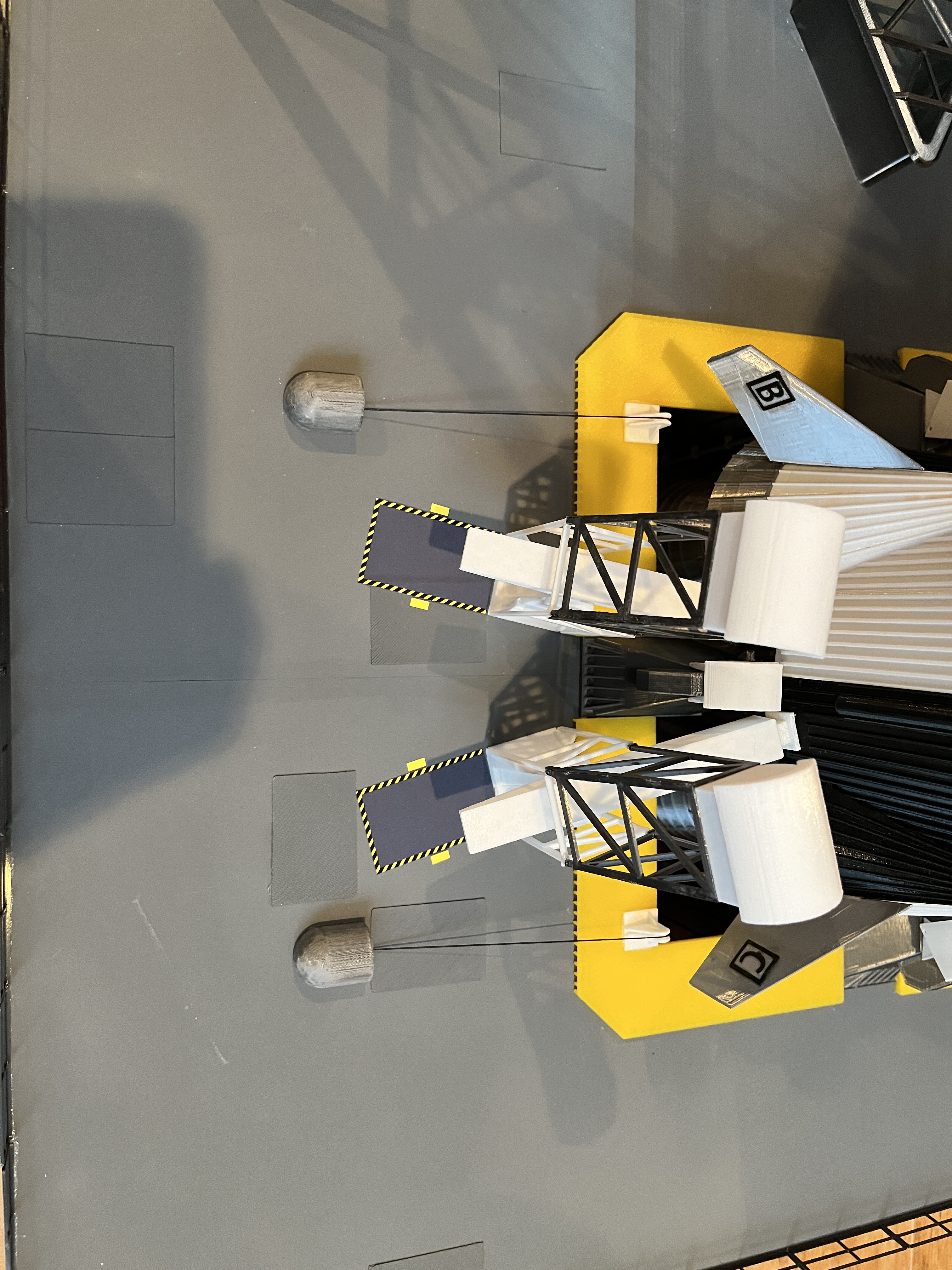
The launcher railing is on. I chose to make my own to match the look of the other railings on the model. I chose not to add the gutters. Here are how the parts lay out: Short sides (side 1 &3): 6 - double sections and 1 - one and a half section Side 2: 6 - double sections and 2 - single sections Side 4: 8 - double sections The two single sections of side 2 are on either side of the ECS pipes.
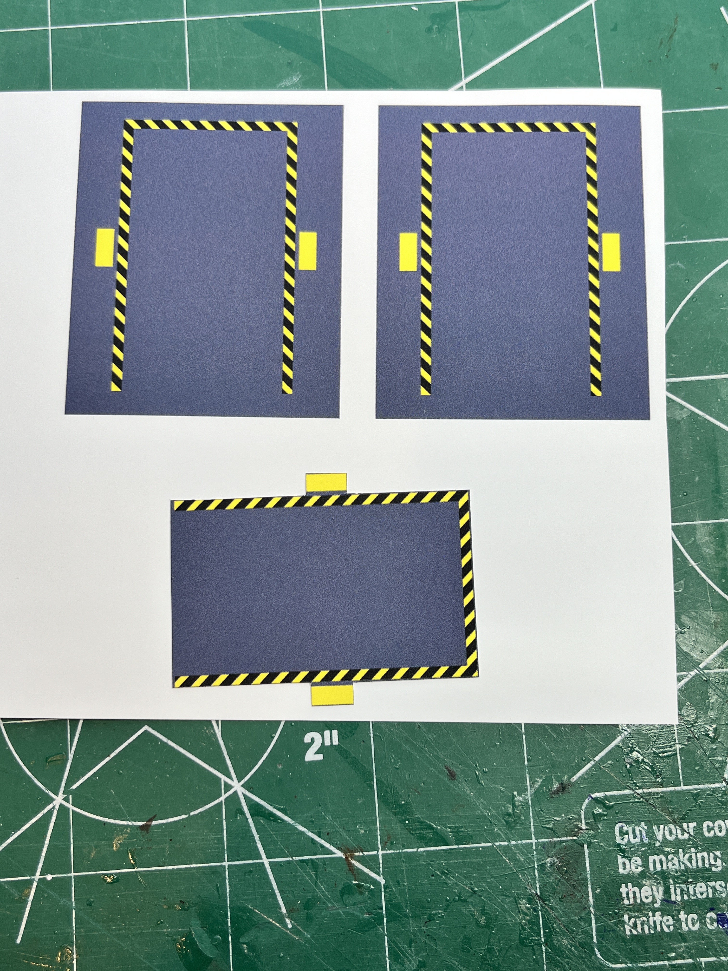
Here are the warning box decals. I printed them on a vinyl sticker sheet using best quality. Notice that I had the background grey extend beyond the yellow/black areas because if these areas were surrounded by white then you would have cut into these yellow/black areas to make sure a white rim was not around the part. The way this is printed you should cut them out by cutting just beyond the yellow/black areas leaving a little grey which will blend into the grey surface. This leaves very straight printed lines. I chose to leave the center section because I though it would be too hard to apply the decal without this. You may feel different. The grey is a bit darker but I figured that is OK because it is surrounded by the yellow/black border.
Here are small side vents on side 1 and side 4. There is also a pair on side 2.


 Tower Section #2 and Swing Arm #2 Complete: The next removable section of the tower is complete. This completes right at 1/3 of the tower! The first stage of the rocket can now be fueled. The swinging arms are working well. This section added 5 cameras. All but the Side 1 photo have the lights on. I am happy with the lights. Swing Arm #2 is now published. Looking at the zoomed in pictures I just realized the walkway stairs to Swing Arm #2 are oriented incorrectly. Oh well. I will probably leave them this way. It would take quite a bit of work to remove and replace the walkway.


 The other method used is to slice the perimeter beams long ways through the webbing. This leaves a very visible seam along the top and bottom of the flanges. Again, not the best solution.
 What I will do is create two pieces, a flange and a combination of the other flange and the webbing that form a "T" shape. This will place the joint not on a flat surface but at a 90 degree connection point. Combining the two pieces does not have to be exact, just make sure the two pieces are weighed down to form a good flat surface. This is what I did with the crawler and it worked well.