 MughtyWinky
-
State Machine works + some thoughts about the power source
01/31/2017 at 20:07 • 0 commentsJust a quick update. Today I implemented the state machine, which was presented in the last log. Now its possible to to switch between manual and auto mode and use the up and down functions.
In a next step the circuit will be moved from the breadboard towards a pcb and mounted into a case. This allows me to do basic tests on the finished hardware.
To ensure portability and to keep the system modular, I choosed to build a external "power box", that will provide the necessary voltages to drive the camera and the barn door. It also can be used without the tracker and will be fed from a 12 volt battery.
The system needs:
- 3.3 volts, 0.1 (?) amps (atmega)
- 8.2 volts, 2 amps (camera)
- 6.8 volts, 1.7 amps (stepper)
which accumulates ( ;-) ) to about 2.8 amps @ 12 v, using 85% effective step down regulators and pretending that the camera and stepper will draw a constant current. Typical lead-acid batteries provide > 7.2 Ah and therefore a running time up to 2.5 hours. In practice this will last longer, as the system won't draw the maximal current over the time.
I think i'll leave some space for a additional 5 volt output, on which i could connect a Raspberry Pi zero. It could controll the camera using pkTriggerCord or PK-Remote and transform the barn door tracker into a standalone piece o technology.
So the next steps are:
- Building th pcb and case
- Building the barn door hardware
- Testing electronics and hardware
- Design a cycle-saving way to calculate the step time
- Calibrate the step time
- Take some sample pictures and hope for the best
- Buy a raspberry pi zeo :-)
-
Finite State Machine
01/24/2017 at 13:17 • 0 commentsUnfortunately the hardware parts aren't ready yet, as i hoped during my last post. So there is time to investigate the state machine, which will drive the barn door.
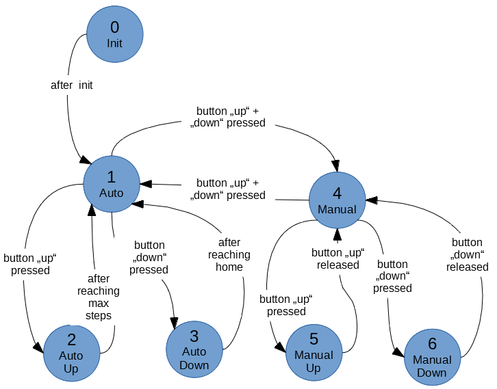
There are seven states which describe the planned functions. These states are shown in the following picture.
![]()
State 0 represents the initialisation step. Here the inputs and outputs will be configured, the barn door will be homed to its starting position and the button interrupts are attached. Thats basically what's done during the setup() routine. Afterwards it will change to the next state and enter the loop().
State 1 means that the barn door is idle and in automatic mode. The state only changes, when one or both buttons are pressed. Pressing the "up" button will change it to state 2, if there are steps left which will manipulate the upper arm. Pressing the "down" button will change it to state 3, if the arm isnt in home position. Pressing both "up" and "down" buttons at once will switch to state 4.
State 2 will be the main mode, where the stepper will move the upper arm to even out the earths rotation. After a maximal number of steps is reached, the upper arm will be fully errected and the stepper will stop. The programm will go back to state 1.
State 3 moves the upper arm back to its home position, as it will rotate backwards until a end stop signals that the arm has reached its home position. Afterwards it will change the state back to 1.
State 4 represents the manual mode. Pressing both "up" and "down" buttons at once will switch to state 1. Other than in state 1, the buttons need to be hold to move the upper handle. While button "up" is hold, the state 5 will move the handle up. When button "down" is pressed, stet 6 will move the handle down.
State 5 will move the handle upwards. The speed will increase while to button is pressed. After the button is released, it will change back to state 4. It will also change to state 4, when the end of the rod is reached.
Step 6 works as step 6, turning the stepper in the opposing direction. This will move the arm down, while the button is pressed or until the home position is reached.
Im not sure, if its required to insert a pause function in state 2.
Here you can see my first draft idea of how the state machine should work. I will post the final code, when its working :-)
boolean changed = false;
int state = 0;

void setup() {
  //configute inputs
  //configure outputs
  //home the arm
  attachInterrupts();
  state = 1;
}

void loop() {
	if(changed){
	//debounce delay
	//read buttons
	//change state
	changed = false;
	attachInterrupts(); //depending on state
	}
	switch case state:
		//Auto Idle
		case 1:
			while(!changed){
				//wait
			}
			break;
		//Auto up = tracking
		case 2:
                        if(maxSteps - actStep > 0){
			    deattachInterrputs();
			    //do the tracking
			    attachInterrupts();
}                       }
			break;
		//auto down = homing
		case 3:
                        if(endSwitch == false){
			    deattachInterrputs();
			    //home the arm
			    attachInterrupts();
                        }
                        break;
		//Manual idle
		case 4:
			while(!changed){
				//wait
			}
			break;
		//Manual up
		case 5:
			while(!changed && maxSteps - actStep > 0){
				//Move up
			}
			break;
		//Manual down
		//Also test for end switch, as the stepper can loose some steps
		case 5:
			while(!changed && actStep > 0 || endswitch == false){
				//Move down
			}
			break;
}

void buttonInterrupt(){
  changed = true;
  deattachInterrputs();
}
First i thought, that it would be a good idea to change the states during buttonInterrupt(). Unfortunately it's hard to recognize the double button press, as you can't and shouldn't use delay() in an ISR.
If you have any other ideas, how to create some cleaner code, your feedback is highly appreciated. -
Working on the electronics
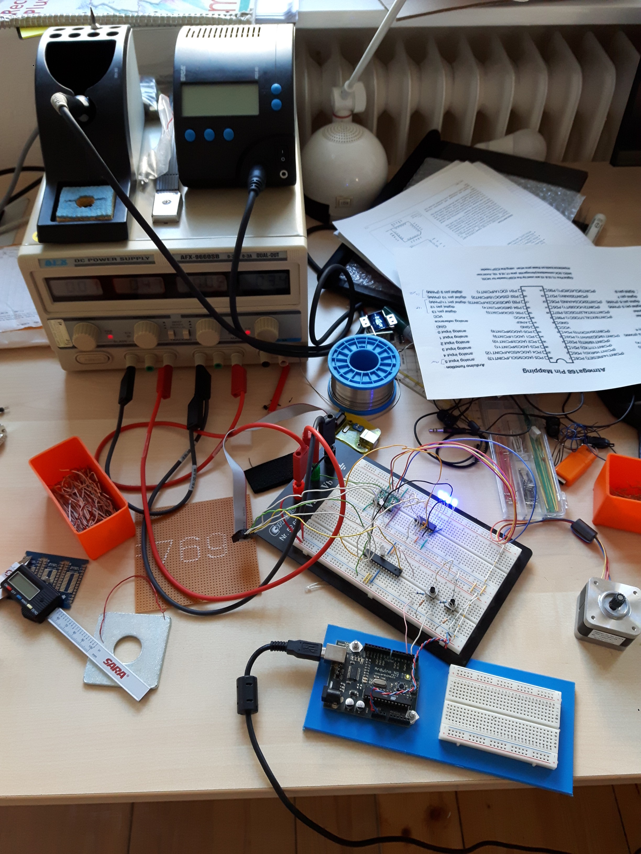
01/19/2017 at 13:40 • 0 commentsActually I am working on the electronics, which will control the stepper. As the "barn door" parts will be ready this weekend, the electronics should at least be able to drive it for a quick test.
A Finite State Machine will be used to control the whole thing. Two push buttons should allow enough interaction. These states are implemented:
- Init (initialisation and homing the barn)
- Manual mode
- Manual up
- Manual down
- Automatic mode
- Automatic up (tracking mode)
- Automatic down (homing the barn)
Pressing both buttons simultaneously will switch between auto and manual mode. Pressing one of the buttons will either move the barn up or down. Below you find a quick snap of my (really messy) workbench.
![]()
-
Some thoughts about geometry
01/16/2017 at 09:52 • 0 commentsAs i wrote in my first log, is necessary to turn the upper bar at a constant turn rate.
Let us first take a look at a isosceles triangle. Thinking about a barn door tracker, we could assume, that the two fixed length sides would be about 40 cm long. The variable side (the threaded rod) will be adjustable between 0 cm and 40 cm. The first case of 0 cm gives us an opening angle of 0°. The second case will form a equilateral triangle, which will lead to a opening angle of 60°.
Assuming that the earth rotates at 360° per 1440 minutes, it will take 240 minutes to open the tracker by 60°. Side c (the rod) needs to be extended at 6 minutes per centimeter.
![]()
Any other angles can be calculated as:
As the movement of the upper bar is constant, we can insert another data point at 30°.
The first 30° section, between 0° and 30°, need to take 120 minutes. At 0° the rod will be 0 cm long. At 30° the rod will be 20.71 cm long. Which gives us a movement rate of 5.80 minutes per centimeter:
The second 30° section, between 30° and 60°, will also take 120 minutes. At 60° the rod will be 40 cm long. Which gives us a movement rate of 6.22 mintes per centimeter:
As you can see, the rod needs to move slower in the upper 30° section than in the lower 30° section.
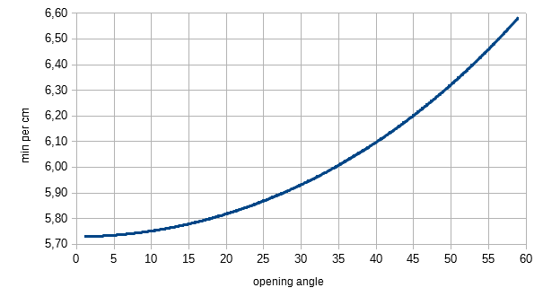
Now we'll split the 60° opening angle into 5° segments, where each segment will take 8 minutes:
start angle end angle length change in cm min per cm 0 5 3,49 5,73 5 10 3,48 5,74 10 15 3,47 5,76 15 20 3,45 5,80 20 25 3,42 5,84 25 30 3,39 5,90 30 35 3,35 5,97 35 40 3,31 6,05 40 45 3,25 6,15 45 50 3,19 6,26 50 55 3,13 6,39 55 60 3,06 6,54 or as a diagram
![]()
This makes it clear, that the rotation rate of the stepper needs to be adjusted on a regular basis.
As a last step, we will convert the length change of the rod into steps per second.
I'll use a TR 12 X 3 rod, where one turn will cause a length change of 3 mm. The stepper has a resolution of 0.9° per step. So each step will change the length by 0.0075 mm.
To change the rod at a speed of 5.73 minutes per cm, the stepper needs to make a step every 0.258 seconds.
At at rate of 6.54 minutes per cm, that value changes to 0.296 secondes per step. -
Introduction
01/14/2017 at 21:46 • 0 commentsMotivation
Space - the final frontier. Spending a night under a starry sky offers a fascinating view into the past. To keep those images not only for one night, it's easy to set up an camera and take some photos.
Unfortunately (?) the earth keeps rotating, which makes it hard to get a picture of a star as a point. As shown in the picture below, this can also be a nice effect.
If you like to capture the stars a points, there's a rule of thumb:![Balanced Rock with Star Trails (NPS/Jacob W. Frank, CC-BY 2.0)]() Balanced Rock with Star Trails (NPS/Jacob W. Frank, CC-BY 2.0)
Balanced Rock with Star Trails (NPS/Jacob W. Frank, CC-BY 2.0)I use a Pentax K-30, which has a crop factor of 1.5. Let's calculate the exposure times (all rounded down to full seconds) for different focal lengths, based on my lenses.
Tamron SP 10-24mm 1:3.5 - 4.5
10 mm = 33 sec
24 mm = 13 secTamron 28-75mm 1:2.8
28 mm = 11 sec
75 mm = 4 sec
Asahi 50mm 1:2
50 mm = 6 secIntroduction
If you would like to take photos with higher exposure times, you need to compensate the rotation of the earth. A simple solution is a barn door tracker, which is shown in the following picture.
![Barn Door Mount (Rob Pattengrill, CC BY-NC-ND 2.0)]() Barn Door Mount (Rob Pattengrill, CC BY-NC-ND 2.0)
Barn Door Mount (Rob Pattengrill, CC BY-NC-ND 2.0)The mode of operation is quite simple. After the hinge is aligned the be parallel to the axis of the Earth, the camera is oriented to the desired area of the sky. To rotate in sync with the earth, the bolt needs to be turned at a defined speed. As the earth rotates 360° in 24 hours (or to be more correct 23 hours, 56 min, 4.1 sec), the included angle between the two sheets of wood needs to increase
- 360° in 24 hours
- 15° in 1 hour
- 3.75° in 5 minutes
- 0.25° in 1 minute
Pifalls
As you can imagine, its hard to rotate the bolt at a defined speed by hand, especially during a long time of exposure like 5 minutes.
Also this isosceles mount has a disadvantage, due to its construction. One turn of the bolt will change the included angle in a different way, depending on the size of the included angle. We will take a closer look at this on another post.
Own solutuion
During this project, i will construct a barn door mount, which is operated by a stepper motor. The stepper motor is controlled by a microcontroller, which will turn the bolt at a correct speed, which will be calculated depending on the opening angle.
YABDT - Yet another barn door tracker
How to build a barn door tracker - using a trapezoid threaded rod, a stepper, some phenolic plywood and a bunch of electronics.
 Balanced Rock with Star Trails (NPS/Jacob W. Frank, CC-BY 2.0)
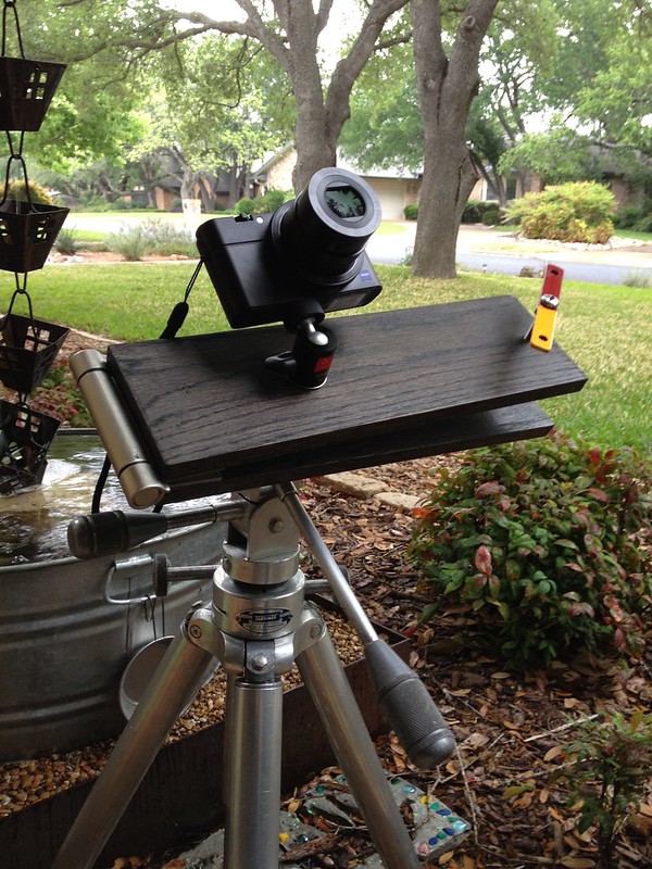 Barn Door Mount (Rob Pattengrill, CC BY-NC-ND 2.0)