-
Colour sensing (2)
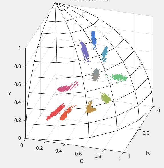
01/10/2024 at 09:32 • 0 commentsTrying a different approach, I took a whole bunch of raw sensor readings whilst holding/moving/rotating different coloured bricks in front of the sensor, at a variety of distances from 5mm to about 20mm. Then imported the readings into Matlab so that I could scatterplot them in 3D (rgb-space) and observed that all the points relating to a certain brick formed a straight line. One end tends towards the origin (black, i.e. poor illumination) but the other end does not tend towards (1,1,1) i.e. white. This means that the shade or hue(1) of each brick does not change with distance or brightness of illumination. We humans might see a white, specular flash from a shiny face, but the sensor just sees brighter red (or whatever colour). I'm sure this effect is obvious and well-known, just not to me.
![]()
RGB values normalised to unit magnitude (very low brightness outliers removed) I think it means, as I suspected, that I can classify the bricks' colours by normalising the rgb values to account for brightness of illumination, resulting simply in hue and ignoring brightness. The down-side is that black, grey and white bricks all get classified the same, and cannot be separated. Maybe that's not a problem, at least for now.
It's also surprising how much 'desaturation' there is, e.g. the green and blue channels show significant responses when shown a 'red' brick. Perhaps it's correct, or perhaps I'm getting light from the illuminator LED scattering directly onto the sensor by accident.
(1) Not really 'hue', since it includes all levels of saturation including grey, so really it's a mix of hue and saturation.
-
Colour sensing
01/08/2024 at 12:08 • 0 commentsI've parked the feeder problems for now, since the TCS34725 colour sensor arrived in the post the other day and I've been playing with that instead.
I knew it was going to be tricky, and I wasn't wrong, but it's halfway there. I can now classify a brick from a library of 'known' colours with reasonable success, even when it's placed at different distances (and therefore vastly different lighting/brightness) from the sensor. I'm using a modified form of the 'redmean' colour distance algorithm, extended to include a fourth brightness dimension using a weighting factor that I'm still experimenting with.
I'm also going to try and find a tiny lens to fit to the sensor, so that its field of view is focussed to a small spot, meaning that the Lego piece size doesn't matter too much. I'll probably also try a separate, more distant light source so that lighting is a bit less dependent on sensor distance.
Nothing much to see yet, photos to follow...
-
Not feeling the vibes...
01/04/2024 at 10:38 • 0 commentsAaagh. The vibratory feeder is turning out to be as difficult as I'd feared.
The plastic vee channel I'm using is so soft that its fundamental resonant mode occurs at pretty low frequencies - too low to make the Lego pieces dance about and separate themselves. Worse, the motor that drives it is so tightly coupled that it too gets locked into the resonances (particularly mode 2) and it becomes impossible to change its speed by simply increasing the current through it. After a lot more experimenting I'm still stuck with mode 2 that includes a dead spot (node) where the vibrations are weak, and the pieces don't move along properly.
I think what I need is a stiffer channel, so that I can drive it at higher frequencies but still below the first harmonic - i.e. the fundamental mode with the uphill end relatively fixed forcing the downhill end to waggle the strongest, no nodes. Cantilever beam, mode 1. Or even operate below first resonance?
Notes to self:
Beam type mode 1 (KnL)2 Fixed-free (cantilever) 3.52 Free-free 4.73 Fixed-fixed 4.73 Since frequency is proportional to (KnL)2, might want to choose free-free or fixed-fixed as they have slightly higher fundamental mode frequencies. Both have nodes though. Maybe fixed-fixed, and take of the pieces just before the exit end (where the node is)?
Clearly more to do...
-
Starting to take shape
01/02/2024 at 12:19 • 0 commentsDiverter:
I've nearly completed the diverter build now, and have got the stepper motor running under Arduino control and tuned to go as fast as possible without mis-stepping. With eight possible positions, the diverter needs to move - at most - halfway round the ring, which takes 160 milliseconds. (Moving to the neighbouring position takes only 62ms.) A Lego brick dropped into the top of the diverter takes at least 132 milliseconds to drop out of the other end (t = sqrt(2d/g), i.e. assuming in free-fall - in reality it will mostly likely take a bit longer whilst the piece bounces around inside). This means we need to have finished the colour measurement and classification process about 30ms before the piece enters the top of the diverter tube to be sure of it arriving at the other end in the right position. It also means the machine will never process pieces faster than about 6 per second, however clever/fast it is, but y'know that's fast enough.
Feeder:
Some interesting experiments with a 500mm length of vee-shaped plastic channel. I've fitted a small motor under one end, and attached an off-centre mass (a plastic hub with a few screws in) so that it vibrates everything. I've been playing with varying the position and stiffness of the springy mounts which support the channel, plus the motor speed and incline of the channel, and observed some interesting effects:
- (obviously) changing the incline changes the speed at which the bricks move along the channel
- increasing the amplitude of the vibrations 'jiggles' the bricks and helps them to separate from each other; only quite small vibrations are required just to move the bricks along.
- choosing the right motor speed causes a resonant mode to be set up in the channel, such that one section vibrates more strongly than others. Bricks in these regions tend to separate from each other and move along more quickly.
- So, by carefully tuning everything, I hope to vibrate the channel most strongly at the 'exit' end, so that a pile of bricks dropped at the 'entrance' end move slowly at first, increasing in speed and - critically - separating from each other before they reach the exit, appearing one at a time past the colour sensor and into the diverter.
Well, that's the plan anyway...
-
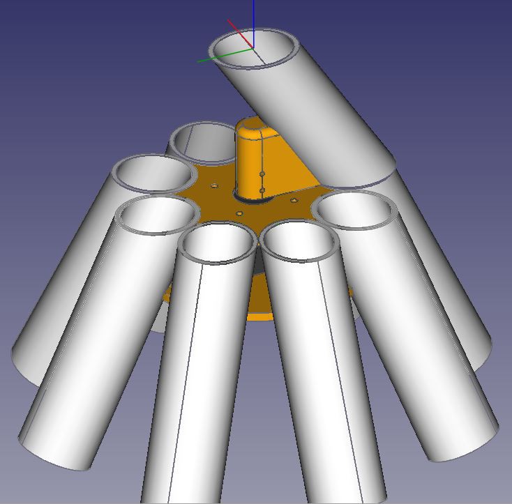
Diverter
12/28/2023 at 12:34 • 0 commentsSome initial CAD work on the diverter...
![]()
Design goals:
- eight ouput tubes
- NEMA 17 motor
- minimise moving mass so that it can start/stop/move quickly between positions
- keep transit path short so that pieces are processed quickly
- minimal parts count - use 40mm pipe, 3D printed parts and adhesive only - just a few screws.
-
Initial thoughts
12/28/2023 at 12:33 • 0 commentsThe machine needs to consist of five sections, in reverse order:
- a number of bins to collect the sorted pieces
- a 'diverter' to direct each part into the correct bin
- a sensor and controller which can determine the correct bin (by piece colour) and control the diverter
- a feeder to feed parts to the sensor one at a time, and then on to the diverter
- a drum, bucket or hopper to hold a mass of Lego pieces
After a bit of thought and some inspiration from here and here, the concept is:
- a "drum feeder" to hold the bulk pieces and supply them at a rate (controlled by the rotation of the drum and the size of the scoops) to the feeder.
- a "vibratory linear feeder" to simultaneously separate the pieces and transport them to the sensor and beyond.
- a colour sensor e.g. TCS34725 module connected to an Arduino Nano to estimate/classify colour, and control the diverter and linear feeder
- a rotary diverter powered by a NEMA 17 stepper to divert pieces into one of eight collector tubes
- a circle of tubes which allow pieces to slide (under gravity) to eight bins/bags.
I hope to use 40mm plastic pipe for most of the build, as it's cheap and large enough for most Lego pieces to fit through.
Colour sorting machine for Lego
Automatically sort random Lego pieces by colour!