 Adam Quantrill
So far, I have cut away the back aly body, and exposed the driver boards, with hardly any damage.
It looks like there are a bunch of driver IC's attached to the drivers, under what at first looked like kapton tape, but now appears to be some sort of flexi-circuit taking the oled drive to the front of the screen. See pic of one partly peeled up.
One idea I had was to power it up (see below*) and strap strong LEDs to the driver chips, which might activate the drivers, and as I switch the LEDs it will switch the drivers on and off, in unpredictable ways.
* I need to identify the power rails and what the rail voltages are. GND is easy.
If you know what the OLED drive voltages might be for R, G and B that would be interesting.
It's an HD display so ~1000x720x3? But I count only around 600? lines to the front through the flexis. So it's still a mystery how the individual LED's are addressed/powered.
NEW: I found this, not the right board, but, probably gives some clues: https://www.lcdledsolutions.com/circuitpdf/pdf/oled65g6p-t-con.pdf
Yes, the digital interface is called "V by 1" or Vx1. E.G. https://www.cnzgys.com/uploads/allimg/20220403/1-220403192325515.pdf


 Patrick Hickey
 Koen van Vliet
 svofski
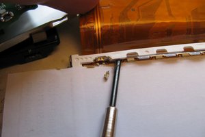
 rawe
rawe
The driver chips on the flex cables take LVDS signals and the timings needs to be correct. You won't be able to drive these "willy-nilly" - It's pretty complicated stuff. Also shining light onto the die will not do anything useful. You need to scan both horizontal and vertical for something to happen.