Tom Thoen
-
Finally Done!!
09/23/2024 at 22:29 • 0 comments![]()
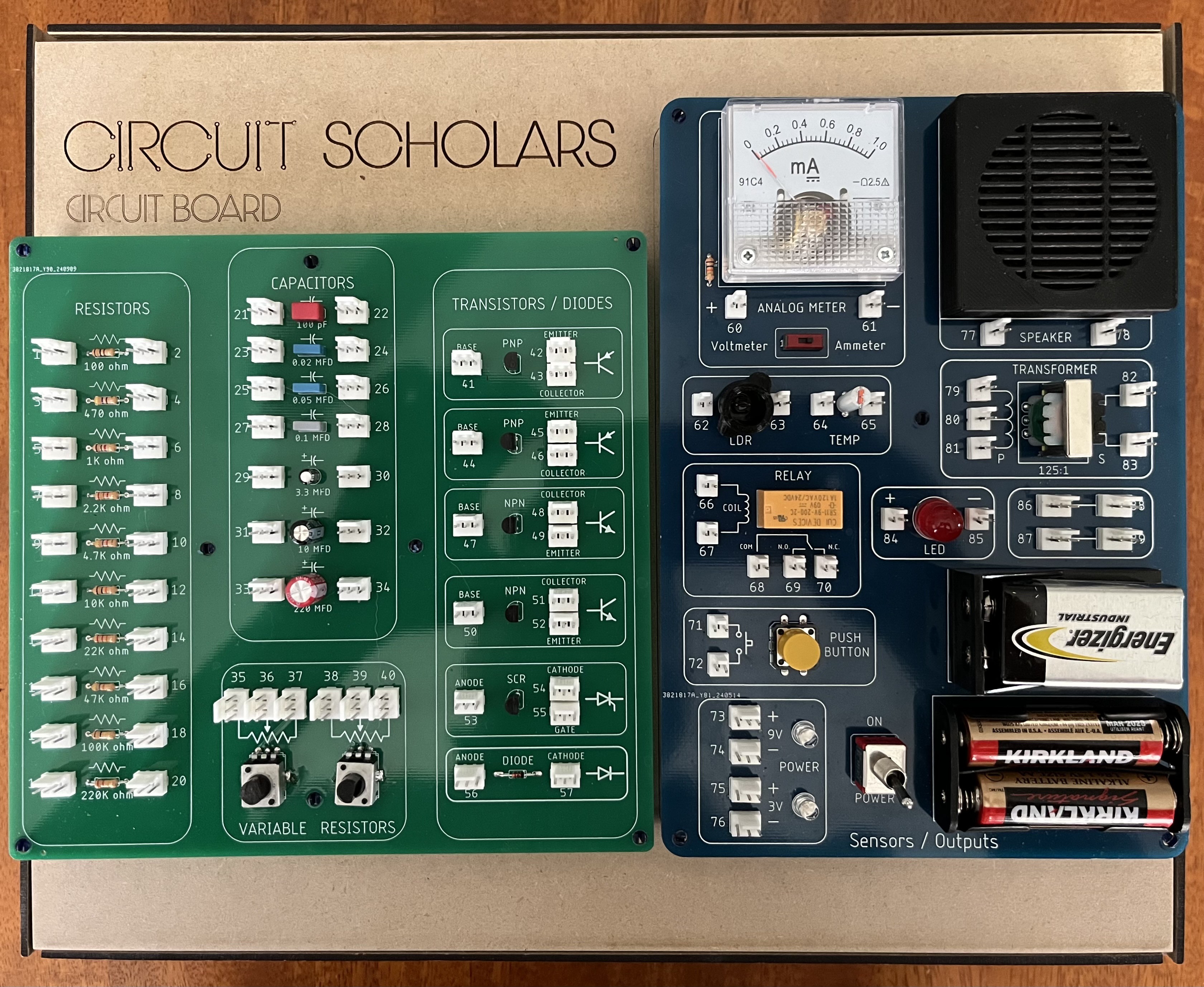
Well, after a lot of travel and other activities this summer I finally completed the project! There are still a few files to add, but the schematics, board files, BOM, and instruction manual are now available for upload.
I combined the smaller discrete boards into a single board - it will be easier to mount this way.
Making PCBs:
The .zip files can be used to order from JLC.pcb. Nothing special about ordering other than choosing the colors!
BOM:
The Bill of Materials is an Excel spreadsheet - note that there are individual tabs for sub-sections and one tab for the whole project.
Instruction Manual:
The instruction manual is a .pdf that is in 9 X 12 format - it can be printed as a full manual.
Other files / parts...
Just added 3D print files for the speaker cover, and LDR and Thermistor tubes, and the laser cut file for the base.
Let me know if you have any questions on the build!!
-
Week 11 - Wiring Charts
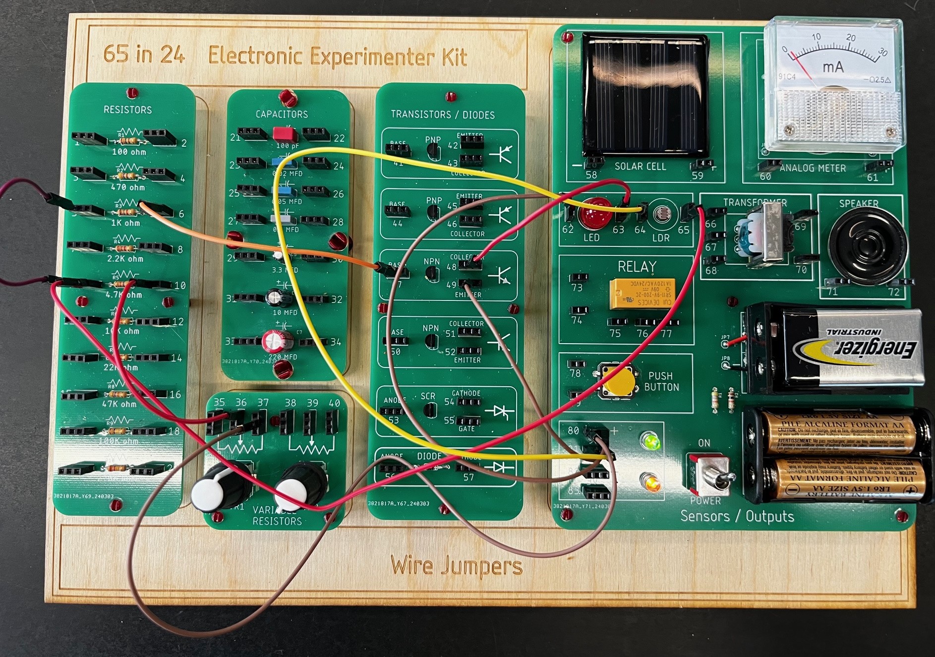
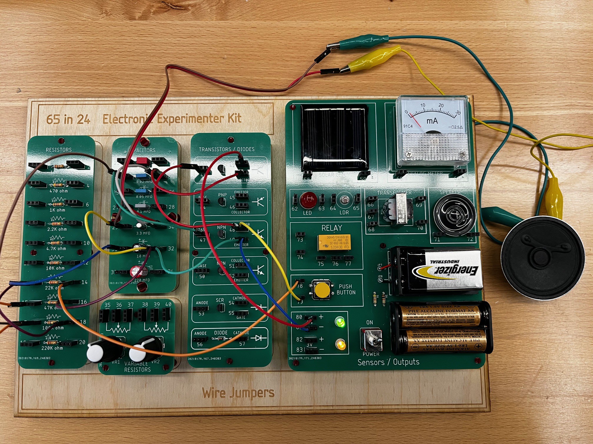
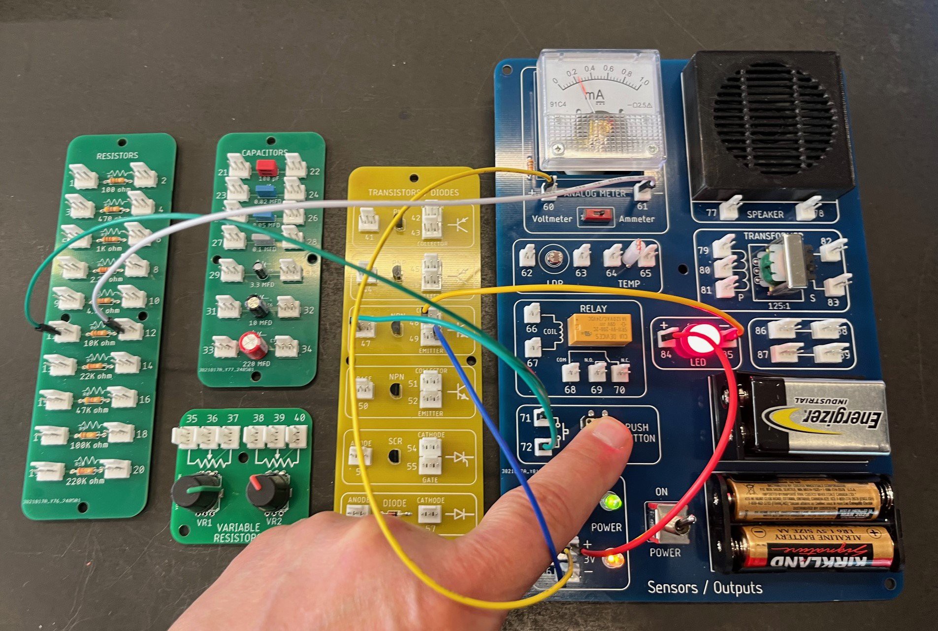
06/06/2024 at 23:03 • 0 commentsTo verify that the circuits work I'm wiring each project, verifying they work, and creating wiring charts - tedious but necessary! The experiment below is showing the current gain in a simple NPN transistor circuit.
![]()
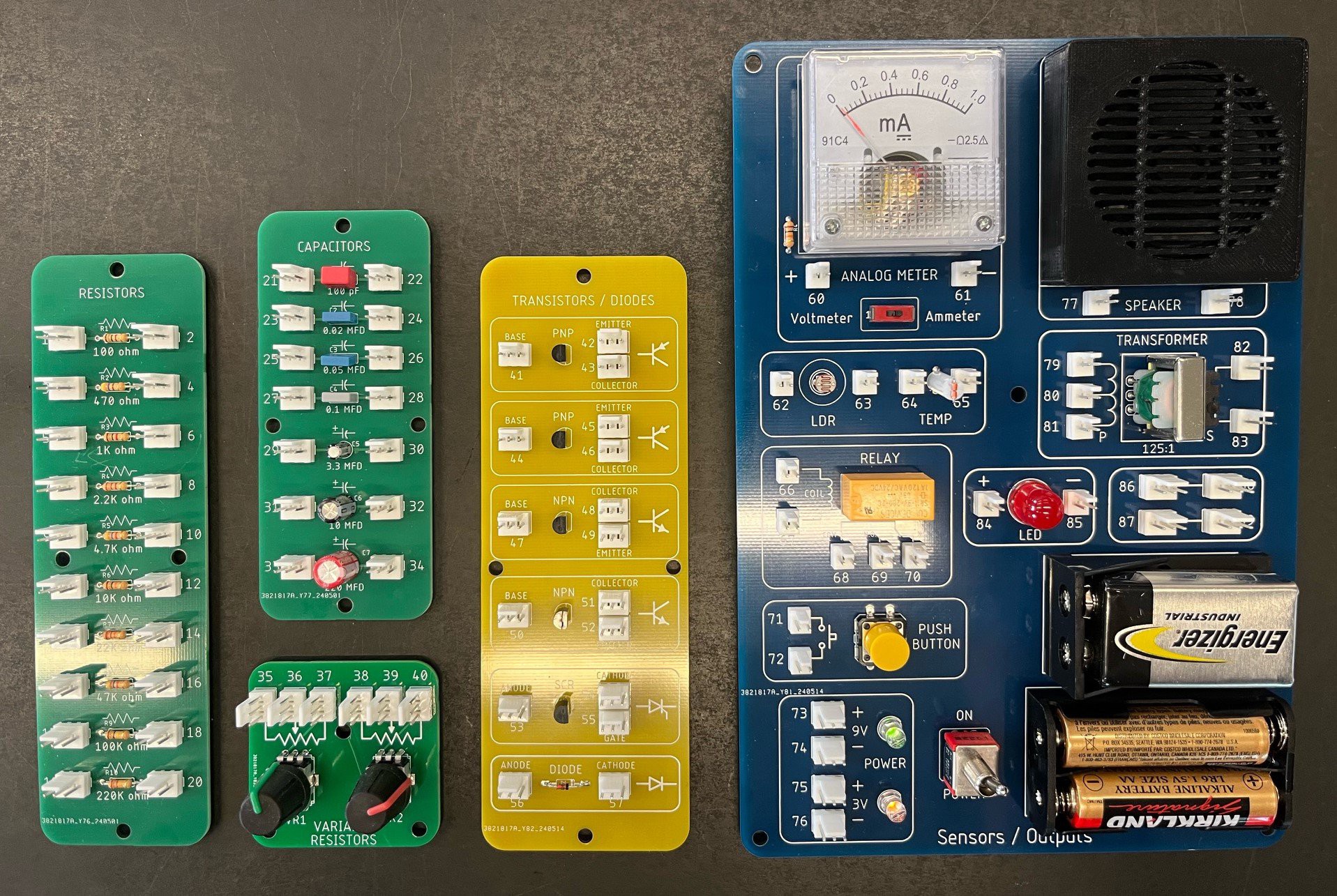
The original wiring charts from the kit - updating to the new connection pin numbers in Excel...
![]()
-
Week 10 log - PCBs done / enclosure
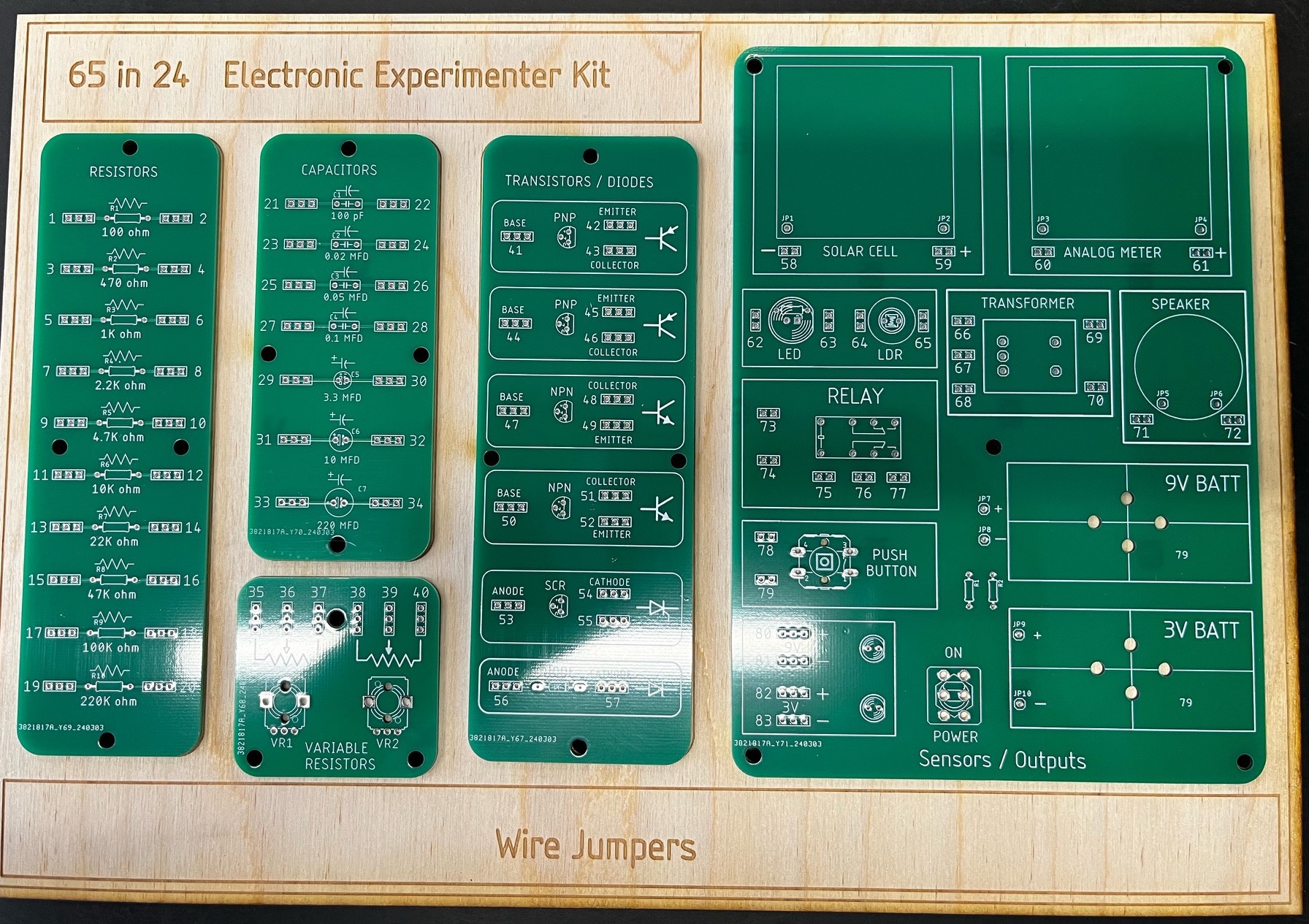
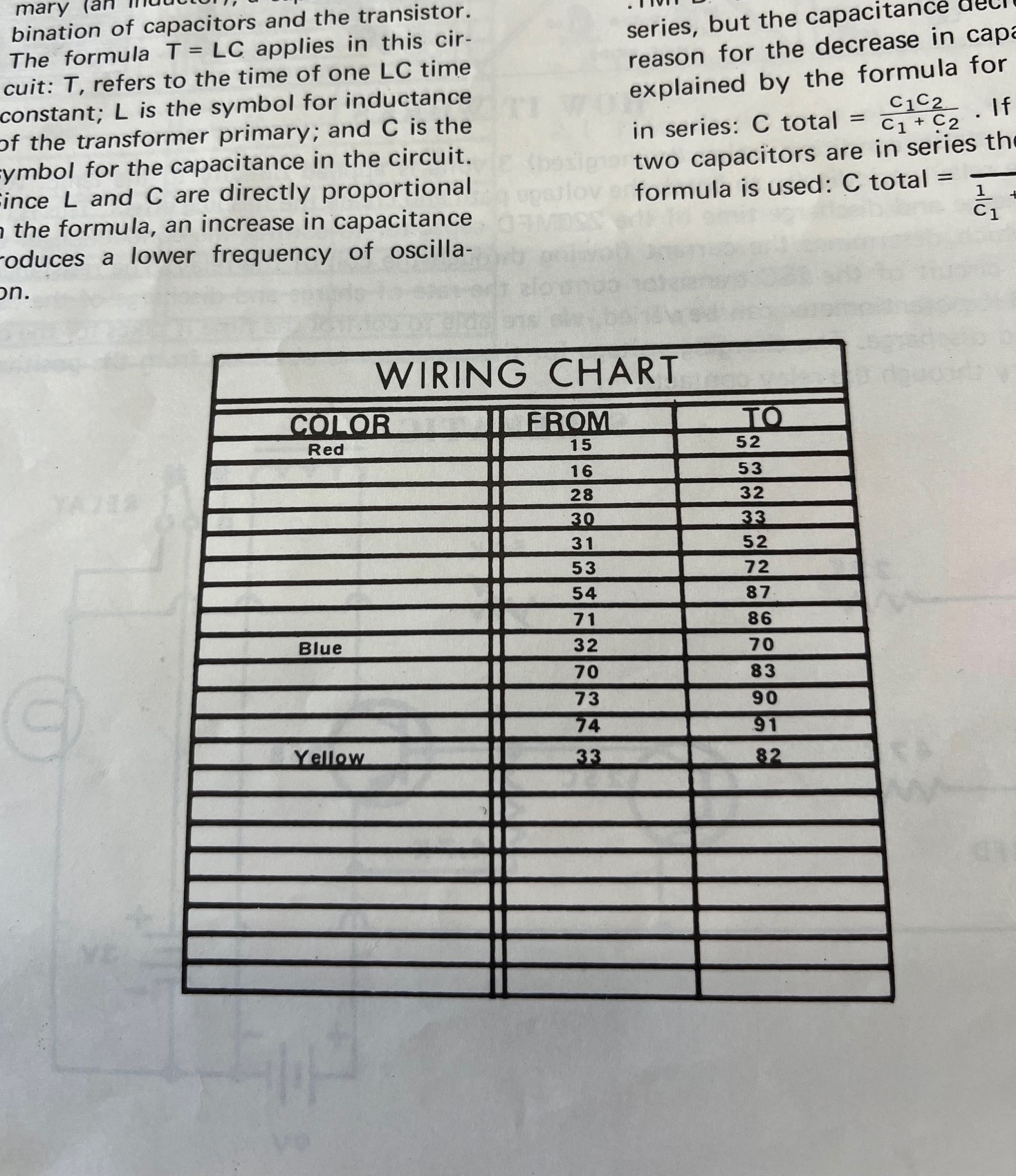
05/30/2024 at 21:39 • 0 commentsThe PCBs are finally finished! I used different color solder masks to capture the look of the original kit. I will be uploading the Eagle files and BOMS shortly.
![]()
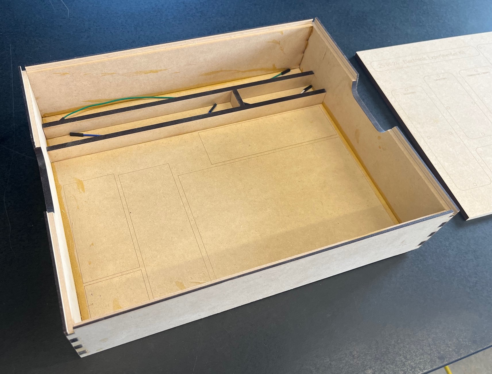
Tiffany has designed a panel and enclosure she is finalizing this week. More photos coming soon!
![]()
The manual is in process but will take some time as every project needs to be tested and documented for accuracy.
-
Week 7ish
04/30/2024 at 22:26 • 0 commentsFor creating the manual a number of illustrations are required. Through the Design Lab I was connected with an Art Center student named Tiffany. She is a fantastic artist and is helping re-create the original cartoons from the manual with a more modern feel...here is one of her preliminary ideations:
![]()
So, it's time to work on documentation! As before, my goal is to finalize the designs, build a number of samples and do some "in-class" testing. Still a few weeks out on the manual, but making good progress!
The board designs are finally completed and 25 experiments have been tested! I'm going with different colors on the soldermask to pay homage to the original board.
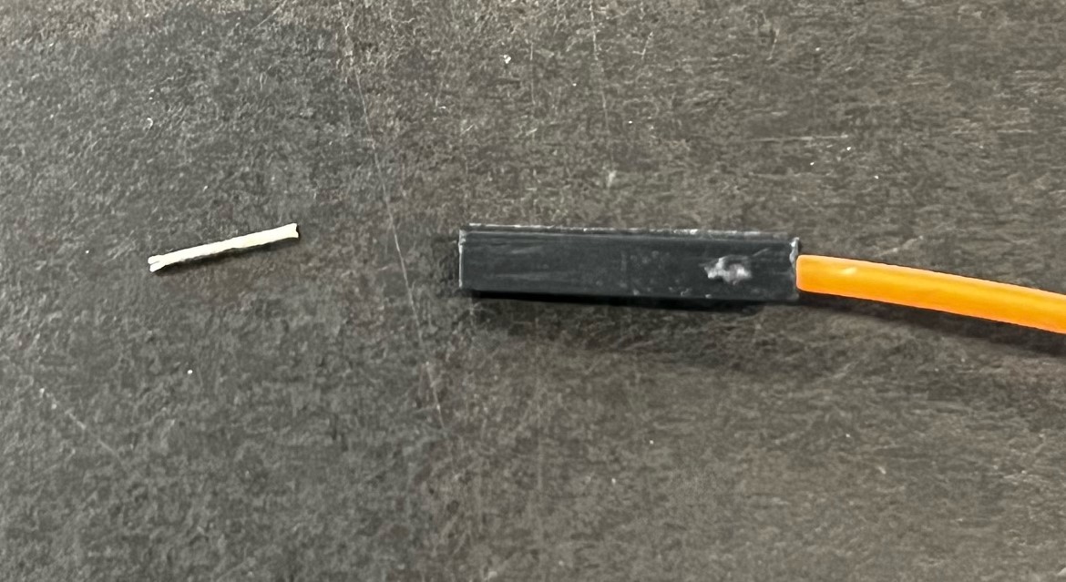
One of the more difficult aspects was determining the connection points for the jumpers. The male wire pins tend to break after the wires are pulled out several times - so I am going with FF 20 AWG jumper wires.
On the board I originally was going to use regular male pin headers which are durable - however they are a bit sharp! So, for now I am going to use shrouded headers (Molex) that at least will protect the user. I feel like this is a critical point as the project reliability depends on how well the connectors work after multiple projects are tested and disassembled.
![]() I am hoping to have a fully functional prototype in about two weeks, with at least a preliminary manual...
I am hoping to have a fully functional prototype in about two weeks, with at least a preliminary manual... -
Week 6 - Final project testing / PCB design
04/04/2024 at 23:02 • 0 commentsFinally tested the last projects.
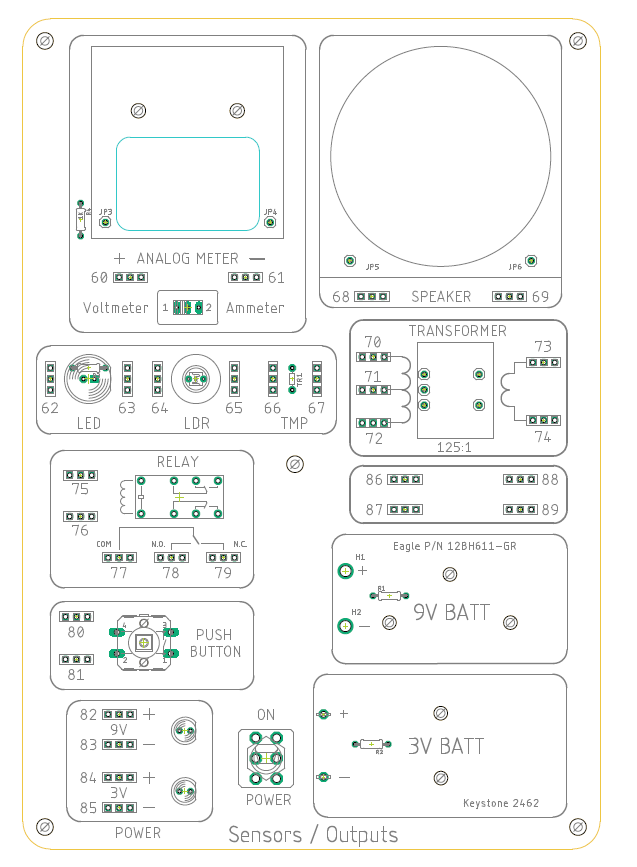
Revised the Sensors / Outputs PCB - using 3 pin headers to transition to SMT so they don't all have to be soldered manually. Here is the final layout:
![]()
My next plan is to solder up 3-4 of these boards and have people test them out for functionality / look / feel.
-
Week 5B - Next steps
03/28/2024 at 23:05 • 0 commentsNext steps:
- I still have a number of projects to test - documentation is going to be the biggest time challenge.
- Modifications for the Sensors / Outputs board - need to spin up a new PCB.
- Once everything is working create a BOM / PCB files / some kind of basic instruction document. Ultimately this will be a big task to replicate the original manual from Radio Shack, which was very good!
- Finalize design of overall box - most likely laser cut from wood.
- Start Phase 2 - Digital logic circuits!
-
Week 5 - more testing!!!
03/26/2024 at 18:31 • 0 commentsSo far I've been able to get about 8 experiments working.
Lessons learned:
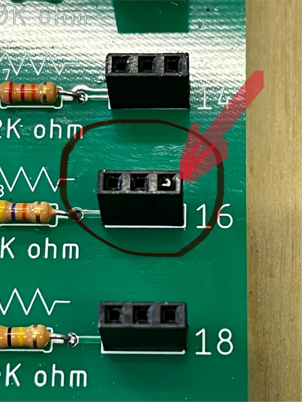
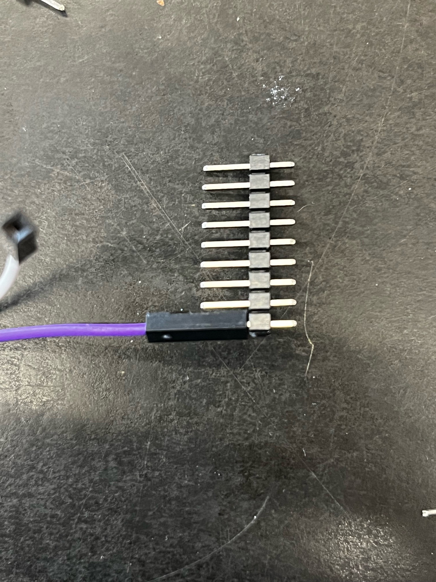
The wire jumper ends break fairly easily, especially when I "rip" them all out of the board (memories of 5th grade!). This also often leaves the pin stuck in the female header. Also, the typical Dupont wire jumper pins are a bit small for the female sockets - they are a bit loose and don't make reliable connections and pop out of the sockets easily. I did this originally to keep the sharp pins off the board, but now the plan is to replace the female sockets on the board with male .025" header pins. The female to female jumper wires are much more secure on the header pins and the typical header pins I use are pretty robust. Plus, they won't break!
Maybe you think I'm overthinking this, but if this part of the board doesn't hold up, it will be very frustrating to the user!
As there are a few other changes I'll be making I'll spin up another rev on the PCB designs. The speaker sounds tinny as it's so small, so I'll probably replace the Solar cell real estate with a larger speaker...
![]()
![]()
![]()
-
Week 4 - Project testing
03/19/2024 at 23:16 • 0 commentsMixed success this week - I was able to get two projects working; however several others did not work. Not sure if the issue is difference in components or not. At this point I'll probably work on circuits *based* on the original projects but tweaked to work with my new hardware.
Project examples (need to create YouTube videos... :-o )
Light meter:
![]()
Siren:
![]()
(Note that original speaker on PCB is pretty small and not very loud!!
-
Week 3 part 2 - testing
03/14/2024 at 23:14 • 0 commentsWell, initial testing was more difficult than expected - took about five hours just to get a couple of basic circuits working. Made a number of incorrect assumptions / mistakes including:
- Assuming it might be differences between components (germanium vs. Silcon, transformer winding ratio, meter current)
- Blaming the jumper wires (a bit old and janky)
- Rushing too much when making the circuits
Finally found out my resistor board PCB traces had not been routed 100%. Yikes! After re-soldering the board a couple of the projects are finally working. Next step is to get a number of them fully tested and documented...
![]()
Project # 1 test - tone generator :-)
-
Week 3 - PCBs in, soldering and assembly
03/12/2024 at 23:02 • 0 commentsPCBs came in! Thanks JLCPCB!!
![]()
Soldered up the boards - Kino in the Design Lab Laser cut a cool outline in plywood that I'm using for the base for testing.
![]()
Boards were soldered and mounted. There were some clearance issues with the meter so some extra drilling needed to be done!
![]()
I'm very happy with the layout - Later this week I will be working on testing using some of the original 65in1 experiments.
25in24 Electronics Project Board
Re-vitalizing and modernizing a Radio Shack 65in1 kit for educational purposes - my DesignLab Residency!

 I am hoping to have a fully functional prototype in about two weeks, with at least a preliminary manual...