schuyler4
-
Rev2 Final Calibration
04/14/2024 at 03:52 • 0 commentsI have completed the final calibration for the second revision. The data is as follows:
Voltage:
Meter, Fluke 101
-60.28, -60.4
-54.70, -54.81
-49.86, -49.90
-44.88, -44.97
-39.86, -39.93
-34.93, -35.00
-29.89, -29.94
-24.90, -24.94
-19.92, -19.95
-14.94, -14.96
-9.956, -9.97
-4.972, -4.978
-0.987, -0.989
0.001, 0.000
0.989, 0.989
4.975, 4.984
9.960, 9.97
14.94, 14.97
19.92, 19.96
24.90, 24.95
29.89, 29.95
34.81, 34.87
40.00, 40.08
44.80, 44.88
49.90, 50.03
54.97, 55.11
61.04, 61.1

Resistance:
Meter, Range, Fluke 101
29.57, 1, 31.7,
98.33, 1, 103.3
332.3, 1, 332.8
1081, 1, 1044
10730, 2, 10520
21930, 2, 21410
100500, 2, 97300
339800, 2, 315200
530000, 2, 484000

Capacitance:
Meter, Range, Fluke 101
50.88n, 2, 49.2n
96.73n, 2, 96.6n
1.006u, 2, 1.009u
10.03u, 1, 9.92u
45.57u, 1, 47.32u
This works out to 0.3% relative accuracy for voltage, 10% for resistance, and 5% for capacitance.
-
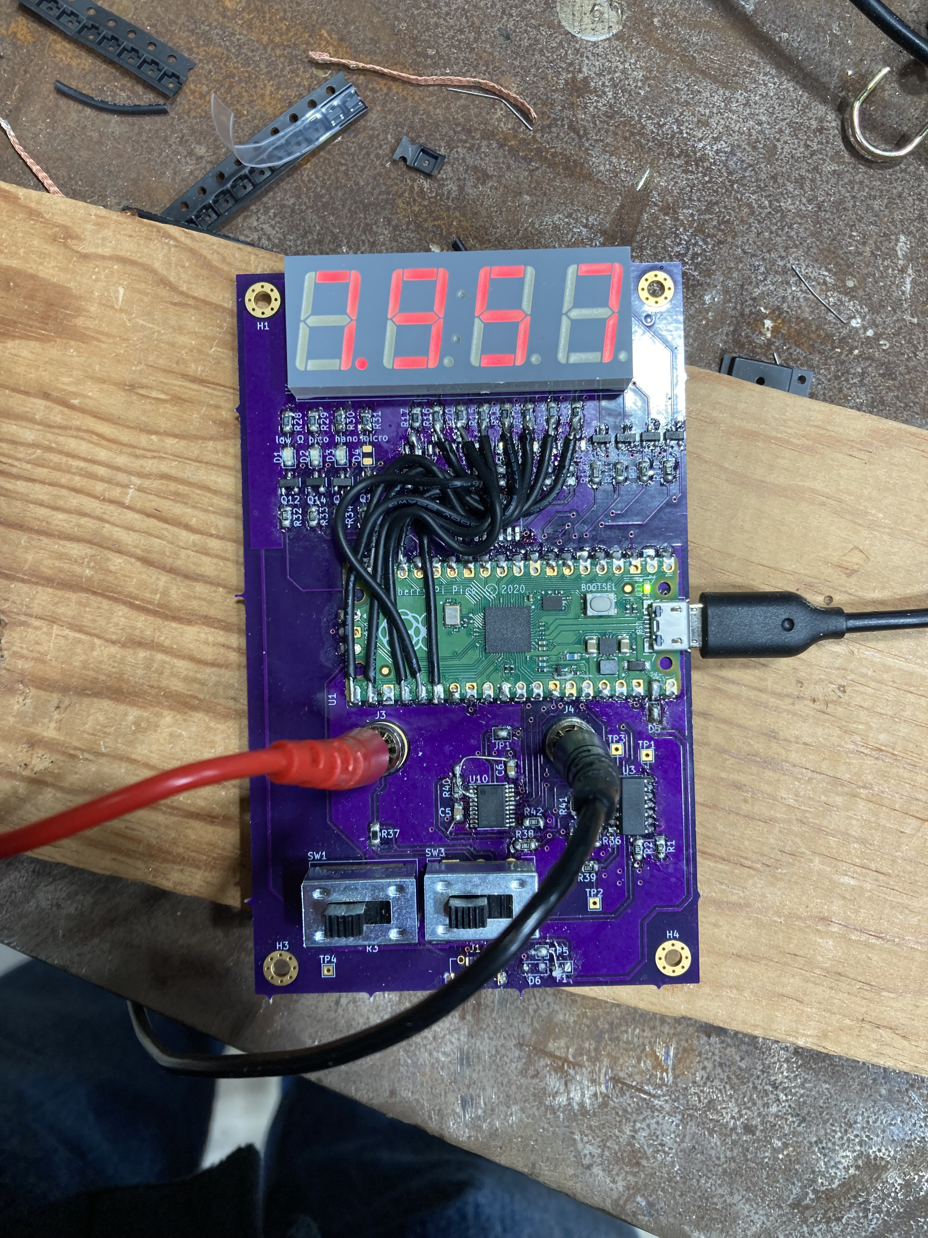
Rev2 PCB Assembly and Bring Up
03/22/2024 at 06:34 • 0 comments
I have assembled and brought up the revision 2 PCB to the point where it reads voltage. Additional firmware is needed for mode switching and calibration is also needed.
-
Rev1 Enclosure
03/20/2024 at 03:57 • 0 commentsI have mounted the first revision into an aluminum sheet metal enclosure with some holes cut in it. The first revision has been repurposed into just a voltmeter because there are some problems with the switching circuit.
-
Rev1 Voltage Test
03/14/2024 at 03:44 • 0 commentsI did another test with the rev1 prototype, this time only measuring voltage, and bringing it all the way to the maximum voltage of 60V. Again I am doing calibration and comparison to my Fluke 101 Multimeter. This has a problem as the Fluke 101 does not have more digits than this multimeter, however, I am ignoring this for now. I was able to stay under 1% error for all measurements, and I think this could be improved with a better calibration procedure. Here are the results:
Voltage(V), Error(%) 0.989, 0.0 4.982, 0.71 9.97, 0.76 14.96, 0.81 19.95, 0.86 24.94, 0.85 29.94, 0.88 34.99, 0.86 40.03, 0.83 44.9, 0.81 49.89, 0.85 54.84, 0.9 59.8, 0.71 -
Rev1 Display Bodge
03/13/2024 at 00:45 • 0 commentsTo make the display work on revision 1, I bypassed the display driver and wired the pico IO pins strait to the segment LEDs. It is a little faint, as the display driver circuit worked completely differently, but it works to test the display.
-
Rev1 Preliminary Accuracy and Precision Test
03/10/2024 at 05:41 • 0 commentsAs the title says, this is a preliminary test of the first version of the multimeter. Before the test, I basically calibrated it using my Fluke 101 as a reference. The results of the test are as follows:
2.5V
Error: 0.569, Coeff of Var: 0.0102

5V
Error: 0.2342, Coeff of Var: 0.001

7.5V
Error: 0.2404, Coeff of Var: 0.0019

10V
Error: 0.0671, Coeff of Var: 0.0006

10ohm
Error: 48.5352, Coeff of Var: 0.0

100ohm
Error: 8.2285, Coeff of Var: 0.0

1000ohm
Error: 0.0443, Coeff of Var: 0.0

10000ohm
Error: 1.9391, Coeff of Var: 0.0

40000ohm
Error: 5.2247, Coeff of Var: 0.1246
As can be observed, the error is fairly low for all the tested voltages. For resistance, the error is higher especially at the low and high ends. It basically isn't accurate at all at 10 ohms. I also did a test of capacitance and for 100nF it measured 579nF, so basically order of magnitude. For 10uF it measured 11.78uF, so close. I may be able to make capacitance better (for 100nF) by increasing the sample rate.
Multimeter
This is my homebrew multimeter design. Included modes are VDC, Ohms, and Capacitance.