Close
0%
0%

Multimeter

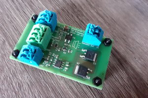
This is my homebrew multimeter design. Included modes are VDC, Ohms, and Capacitance.

Similar projects worth following
This is a basic multimeter design. I have tried to keep it as simple as possible in a variety of respects. Only the most basic modes are included: VDC, ohms, and Capacitance. It is powered via a USB cable, I figure most electronics workstations have an open USB plug, and the design is simpler as there is no rechargeable battery support circuitry. Additionally, to keep the front end simple, there is minimal range switching.

Theory of Operation

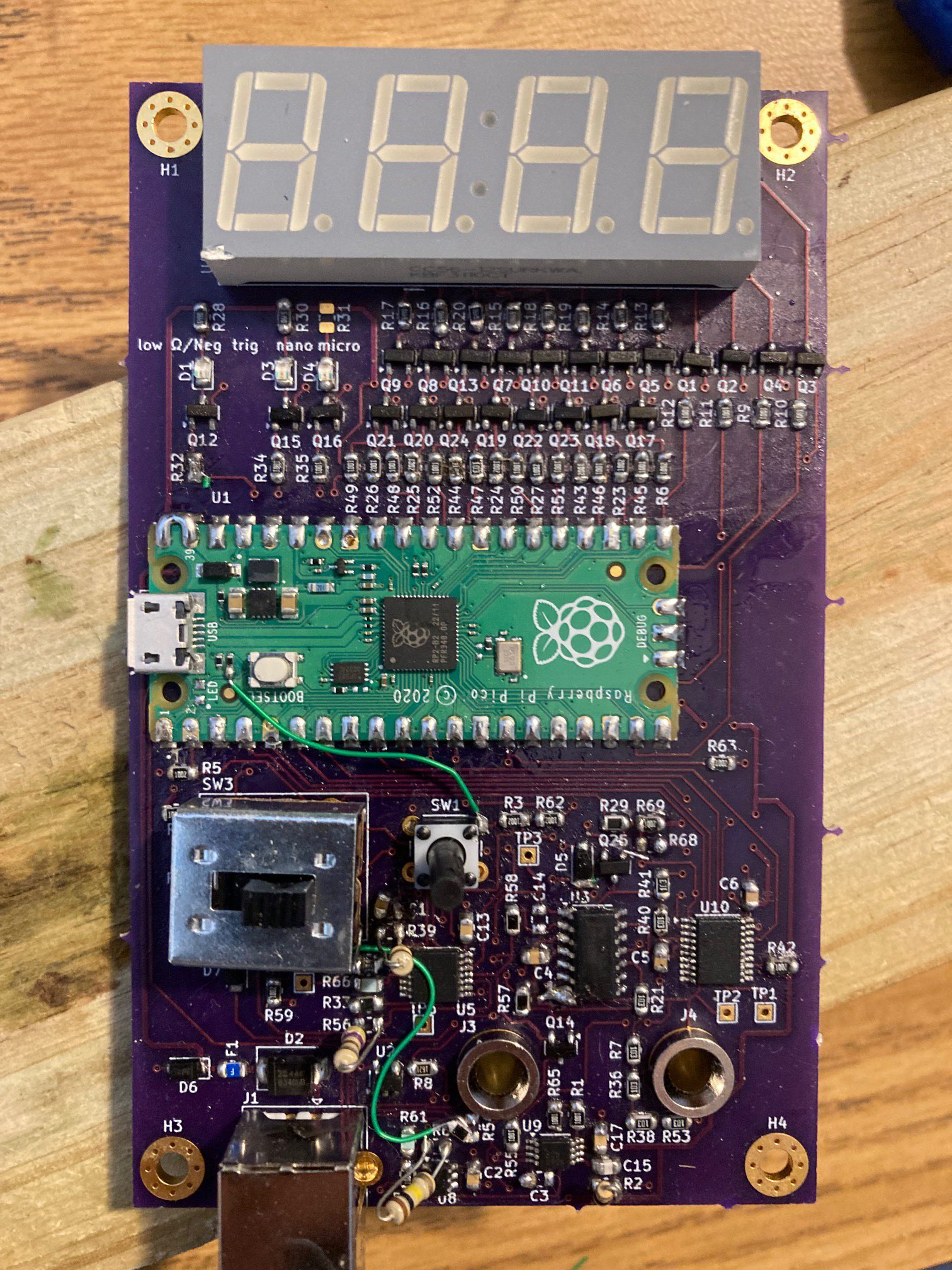
The multimeter is controlled by a Raspberry Pi Pico. This Pico reads digitized data from the front end, computes the voltage, resistance, or capacitance value, and drives the led display to display the value.

Display Driver

For some reason I could not find a chip that would just drive a 4 digit seven segment display that I could easily purchase. Maybe I didn't look hard enough, or maybe it doesn't exist. Instead I basically made discrete IO pin buffers from p-channel and n-channel mosfets.
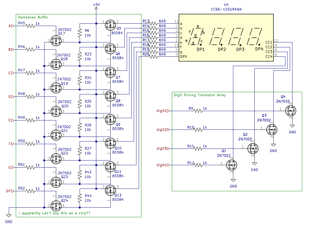
There are also four regular LEDs that indicate things like unit prefix and sign. These are not shown but can be found in the full schematic.

Analog Front End

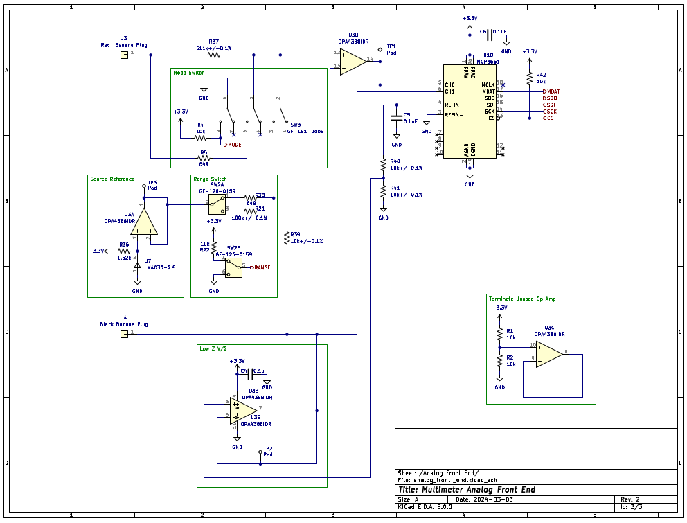
The analog front end conditions voltage readings that are read by the MCP3561 ADC. The conditioning circuit is selected by the various switches. When SW3 is in its default position, the meter is in voltage measurement mode. Switching it changes to component measurement mode. Changing between resistance and capacitance in component mode is facilitated by a logic switch wired up to the Pico (Not Shown). The range switch changes the range in component measurement mode.
Voltage Measurement
As can be observed, voltage measurement mode is a buffered voltage divider into the ADC. Another buffer floats this division at half the ADC reference voltage to allow for negative voltage reading. This floating of the measurement circuit is still there in component measurement mode, which is probably detrimental to performance. 

Resistance Measurement
In component measurement mode, voltage is sourced by buffered 2.5V LM4030 voltage reference in series with the range resistor. There is also another resistor between the measurement node and the input terminal to provide some protection to the device. The combination of these resistors in series, and the resistance being measured creates a voltage divider and resulting voltage that is read by the ADC. The measurement resistance is then calculated in firmware using the known resistances and measured voltage.

Capacitance Measurement
Capacitance measurement is the same as resistance measurement except capacitance. This basically means that instead of measuring a static voltage, the voltage is constantly monitored for a dip that indicates a capacitor was connected. The resulting exponential rise is then sampled, and using the points from this sampling, the capacitance is found. All this computation is obviously done using the Pico. There is a trigger indicator to alert the user that they have triggered on a capacitance.

Improvements

The most lacking part of the design is probably the resistance measurement which only achieves 10% relative accuracy. The biggest issue with the resistance measurement is that it is using a ratio (series resistor) instead of a current source. This becomes a problem when the series resistor is very big compared to the resistance being measured. Additionally, the added series resistor in the network (Between the measurement resistor and the voltage reference series resistor) complicates the measurement algorithm and circuit.
  • Nonlinear Response Fix

    schuyler407/10/2026 at 22:25 0 comments

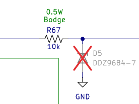
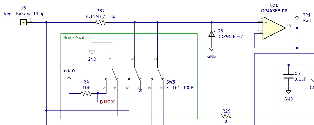
    So here is a simple solution to the nonlinear response caused by adding the protection resistor.

    The op amp has input protection diodes that clamp to the rail, so the zener isn't actually needed. And when it is removed it isn't cracking open at all, so no nonlinear response.
  • REV3 Inadequately Protected Against Stupidity

    schuyler407/08/2026 at 18:33 0 comments

    That is to say, if you have the meter in ohm mode but you are actually measuring a somewhat high DC voltage, it is going to stop being a multimeter and start being a smoke machine. I learned this the hard way.

    Looking at the schematic it is clear why this is the case. 

    In ohm mode the switch will be thrown so R37 will be bypassed. That means unfortunate U3 is just going to eat that voltage (which could be almost 60V out of its operating range) right in the face and D5 ain't going to do shit to protect it. D5 is also going to eat it. 
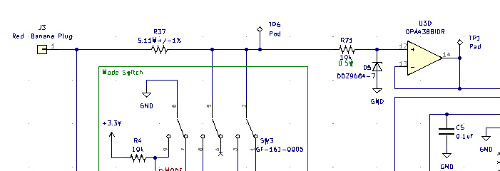
    There is a rather simple bodge that solves this problem: 

    Adding that 10k resistor will allow D5 to clamp the voltage U3 sees to 3.3V and adds a layer of protection. 
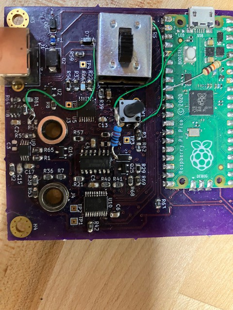
    And here is the bodge bodged on:

    As always it isn't that simple though. U3 is going to squirt or sip some bias current which is going to generate an 8uV offset. In voltage mode this will correspond to a 0.4mV offset in the actual reading. This can be calibrated out though.

    The bigger issue is D5 is a 3.3V zener, but it does start to crack open a bit when measuring higher voltages. This generates a non-linearity in the multimeters voltage response. This is a big problem. More on this to come.  

  • Improved Steady Display

    schuyler412/23/2025 at 04:47 0 comments

    REV3 is coming along well. I have fixed most of the problems, and it is nearly ready for a final test after the new enclosure is completed. 


    One of the most annoying things about REV2 was flicker in the display. Most of the time it was just a few counts of the least significant digit, so not consequential for reading accuracy, but it was annoying and looked amateurish. 

    It turns out it was mostly a firmware/algorithm improvement that fixes this. Hardware filtering before the ADC definitely matters, but what really made the display look good was using an update customized IIR filter instead of just a windowed running average, and adding some hysteresis between real measurement and what was displayed. I considered adding hysteresis a while back, but I ended up not doing it because I couldn't find any evidence that it is used in commercial meters. After further study, I think it is likely that it is implemented to some extent, but just not documented. It is obviously common practice with single bit  analog to digital (comparators), and I just don't see how commercial meters can keep as steady as they do without it. I only added a little over a count, so a little over 1mV of hysteresis in voltage mode. 

  • REV3 Prototype

    schuyler409/30/2025 at 02:50 0 comments

    The prototype for REV3 has been constructed.

    Unfortunately, there seem to small memory effects with the voltage reading after increasing the input impedance to 5.21M ohm in this revision. I'm going to attempt to create an auto zero circuit to compensate for this. In addition, there are a routing issues, and additional IO is really needed, as in this revision the LED pin on the pico board is used.

  • REV3 Design

    schuyler408/20/2025 at 02:38 0 comments

    After using REV2 as basically my daily driver for over a year, I decided it was time to make another revision to take care of some of the problems that are present in the REV2 design. REV3 has not yet been fabricated yet, but here is an overview of the changes. 

    Better Resistance Measurement Circuit

    REV2 basically just utilized a voltage divider for resistance measurement. This approach is not ideal because the ADC codes per ohm is not constant. Also there was only two resistance ranges. The combination of these factors meant that the dynamic range of resistance measurement was not very high - only about 30Ω to 500kΩ, and the accuracy could be as bad as 10% at resistances near the limit of a range. To fix these problems I have implemented a constant current source to measure the resistance in REV3.

    Additionally there are 4 current ranges: 1mA, 100uA, 10uA, and 1uA. 

    Diode Mode

    I have realized that diode mode is useful enough to warrant inclusion on REV3. This will be implemented using one of the current ranges reading out the voltage instead of calculating the resistance in firmware.

    Analog Continuity Circuit
    Previously continuity mode was implemented in software as part of resistance measurement utilizing a threshold. In REV3 I have added an actual amplifier and comparator that will be used with the current source to check for continuity. This way, hopefully the continuity threshold can be very low. I am aiming for 0.5Ω. No More Capacitance Mode
    I decided that capacitance mode implemented with an RC step response did not work well enough, and I don't use capacitance mode on a multimeter very often anyway. So REV3 will not have capacitance mode. 

    USB B Power Plug
    Using the micro USB on the Pi Pico was not ideal. There is now a USB B connector: 


  • cal2

    schuyler406/02/2025 at 02:42 0 comments

    I have done a second calibration on both the full featured multimeter version, and the voltmeter version after ~1 year. No adjustments were needed. I have backed off the voltage spec to 0.5% relative accuracy. Both versions showed slightly higher error when measuring 1V compared to the first time I calibrated them. This leads to a large decrease in accuracy. 1V is low in the voltage range, so small differences lead to large errors.

  • Rev2 Final Calibration

    schuyler404/14/2024 at 03:52 0 comments

    I have completed the final calibration for the second revision. The data is as follows:

    Voltage:
    Meter, Fluke 101
    -60.28, -60.4
    -54.70, -54.81
    -49.86, -49.90
    -44.88, -44.97
    -39.86, -39.93
    -34.93, -35.00
    -29.89, -29.94
    -24.90, -24.94
    -19.92, -19.95
    -14.94, -14.96
    -9.956, -9.97
    -4.972, -4.978
    -0.987, -0.989
    0.001, 0.000
    0.989, 0.989 
    4.975, 4.984
    9.960, 9.97
    14.94, 14.97
    19.92, 19.96
    24.90, 24.95
    29.89, 29.95
    34.81, 34.87
    40.00, 40.08
    44.80, 44.88
    49.90, 50.03
    54.97, 55.11
    61.04, 61.1
    
    Resistance:
    Meter, Range, Fluke 101
    29.57, 1, 31.7, 
    98.33, 1, 103.3
    332.3, 1, 332.8
    1081, 1, 1044
    10730, 2, 10520 
    21930, 2, 21410 
    100500, 2, 97300
    339800, 2, 315200
    530000, 2, 484000
    
    Capacitance:
    Meter, Range, Fluke 101
    50.88n, 2, 49.2n
    96.73n, 2, 96.6n
    1.006u, 2, 1.009u
    10.03u, 1, 9.92u
    45.57u, 1, 47.32u
    

    This works out to 0.3% relative accuracy for voltage, 10% for resistance, and 5% for capacitance.

  • Rev2 PCB Assembly and Bring Up

    schuyler403/22/2024 at 06:34 0 comments

    I have assembled and brought up the revision 2 PCB to the point where it reads voltage. Additional firmware is needed for mode switching and calibration is also needed.

  • Rev1 Enclosure

    schuyler403/20/2024 at 03:57 0 comments

    I have mounted the first revision into an aluminum sheet metal enclosure with some holes cut in it. The first revision has been repurposed into just a voltmeter because there are some problems with the switching circuit.

  • Rev1 Voltage Test

    schuyler403/14/2024 at 03:44 0 comments

    I did another test with the rev1 prototype, this time only measuring voltage, and bringing it all the way to the maximum voltage of 60V. Again I am doing calibration and comparison to my Fluke 101 Multimeter. This has a problem as the Fluke 101 does not have more digits than this multimeter, however, I am ignoring this for now. I was able to stay under 1% error for all measurements, and I think this could be improved with a better calibration procedure. Here are the results:

    Voltage(V), Error(%)
    0.989, 0.0
    4.982, 0.71
    9.97, 0.76
    14.96, 0.81
    19.95, 0.86
    24.94, 0.85
    29.94, 0.88
    34.99, 0.86
    40.03, 0.83
    44.9, 0.81
    49.89, 0.85
    54.84, 0.9
    59.8, 0.71
    

View all 12 project logs

Enjoy this project?

Share

Discussions

Similar Projects

Does this project spark your interest?

Become a member to follow this project and never miss any updates