canique
-
Introducing this project in a video
08/11/2024 at 12:39 • 0 commentsEnglish datasheet (Smartmeter Sense):
https://resources.canique.com/smartmeter-sense/docs/canique-smartmeter-sense-datasheet_1.0.pdf
German manual (Smartmeter Sense):
English datasheet (Infrared adapter):
Introduction in German
Demonstration in German
More details in German
-
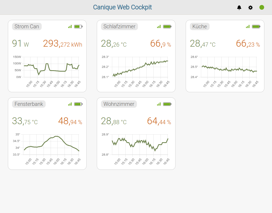
Smartmeter GUI
07/12/2024 at 14:53 • 0 commentsThe complete data pipeline is finished now:
Current consumption in Watt and total Watthours so far are transmitted every 15 seconds from the Smartmeter to a Canique Pico Gateway via 868 MHz radio.
The data is then displayed on cockpit.canique.com and updated whenever new data comes in.
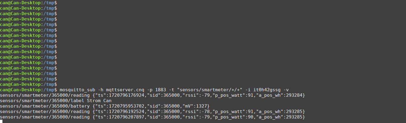
The communication between Pico Gateway and website is via MQTT. You can also configure the Pico Gateway to redirect the data to some other MQTT broker and then process the data yourself (e.g. via InfluxDB, Grafana etc..)
![]()
If we send the data to an MQTT broker running on a Raspberry, it looks like this:
![]()
-
First tests with Landis+Gyr E450
06/01/2024 at 16:06 • 0 commentsToday a first test was conducted with the Canique IR probe connected to a Landis+Gyr E450 smartmeter's optical interface.
The optical interface first needed to be "unlocked" (using an online request form) by Wiener Netze. It took 2 weeks for this to happen. After 2 weeks the 128 Bit decryption key was provided by Wiener Netze.
The data that is sent by the smartmeter obviously is encrypted.
Test setup
The Canique IR probe is connected to a Raspberry Pi4 (3V3, GND, Pi UART RX). The baud rate settings are: 9600 Baud, Parity None (unsure about that), 1 Stop Bit, 8 data bits
The default settings of the Landis+Gyr E450 have not been changed. It pushes an encrypted message once per second.
Data
The encrypted data starts with
7ea067ceff031338bde6e700db084c475a6673d6bbff4f20000a9fb3
in my case and ends with 7e. The whole message is 105 bytes long.
Here is an example of a decrypted message, using a quickly hacked python script:
0f000ab77b0c07e8060106103109ff8000000209090c07e8060106103109ff800080060002f265060000000006000028e9060001a365060000003a060000000006000000000600000031a53edf61a395549644644838a86e600702d4
If you enter this into https://www.gurux.fi/GuruxDLMSTranslator you get a timestamp, and some values.
One of the values is 0x0002F265, which in decimal notation is 193125 Wh total consumption so far.
Another value is 0x0000003A, which probably is the current consumption in W (58W).
Software
The code used to test the infrared interface is located at https://github.com/canique/smartmeter-reader
What's next
Different baud rates need to be checked and different supply voltages. The current consumption of the IR probe needs to be measured while in operation. It's a low power design, though, so it will be very low.
-
Test measurement: IR light to voltage
03/28/2024 at 17:43 • 0 commentsIn a first test setup to measure the IR light as a voltage, the following simple circuit was used:
VCC - IR emitter diode in reverse direction - (Testpoint T1) - 1M resistor - GND
VCC is 2.814V
IR emitter is a Vishay TSAL6200, max reverse current is specified with 10µA
Note 2 things:
- We're not using a photodiode here which would have a higher sensitivity for IR light (it's just not available right now). An IR emitter can also act as a photodiode, although with decreased sensitivity.
- The multimeter that is attached to Testpoint T1 has a ~10M resistance, so a parallel resistor circuit is created here. The effective resistance is (R1xR2)/(R1+R2) = 0.91 MOhm
Test results:
When holding an Infrared emitter (IR remote control) very close to the TSAL6200 and while pressing buttons on the remote control, the max voltage at T1 is measured to be 770 mV. A scope would show more details here, and very probably a higher voltage.
While nothing is pressed, under ambient light from a Philips LED (not IR), 0.13 mV is measured.
If we change the 1M resistor to 7M5, the effective resistance is: 4.28 MOhm
Test results:
While the IR remote control is pressed 1140 mV are measured at max.
While nothing is pressed, under ambient light from a Philips LED (not IR), 1.04 mV is measured.
While holding my hand over the TSAL6200 and thereby creating a shadow, 0 mV are measured.
Now we get an idea that even a bad receiver, which actually is an emitter, can produce a voltage of more than 1V when an IR emitter is placed only a few millimeters away.
Low Power Infrared Energy Meter Monitor
Using the IR diode of smart energy meters this adapter translates the IR signals into UART messages