 SrBlonde
-
1Step 1
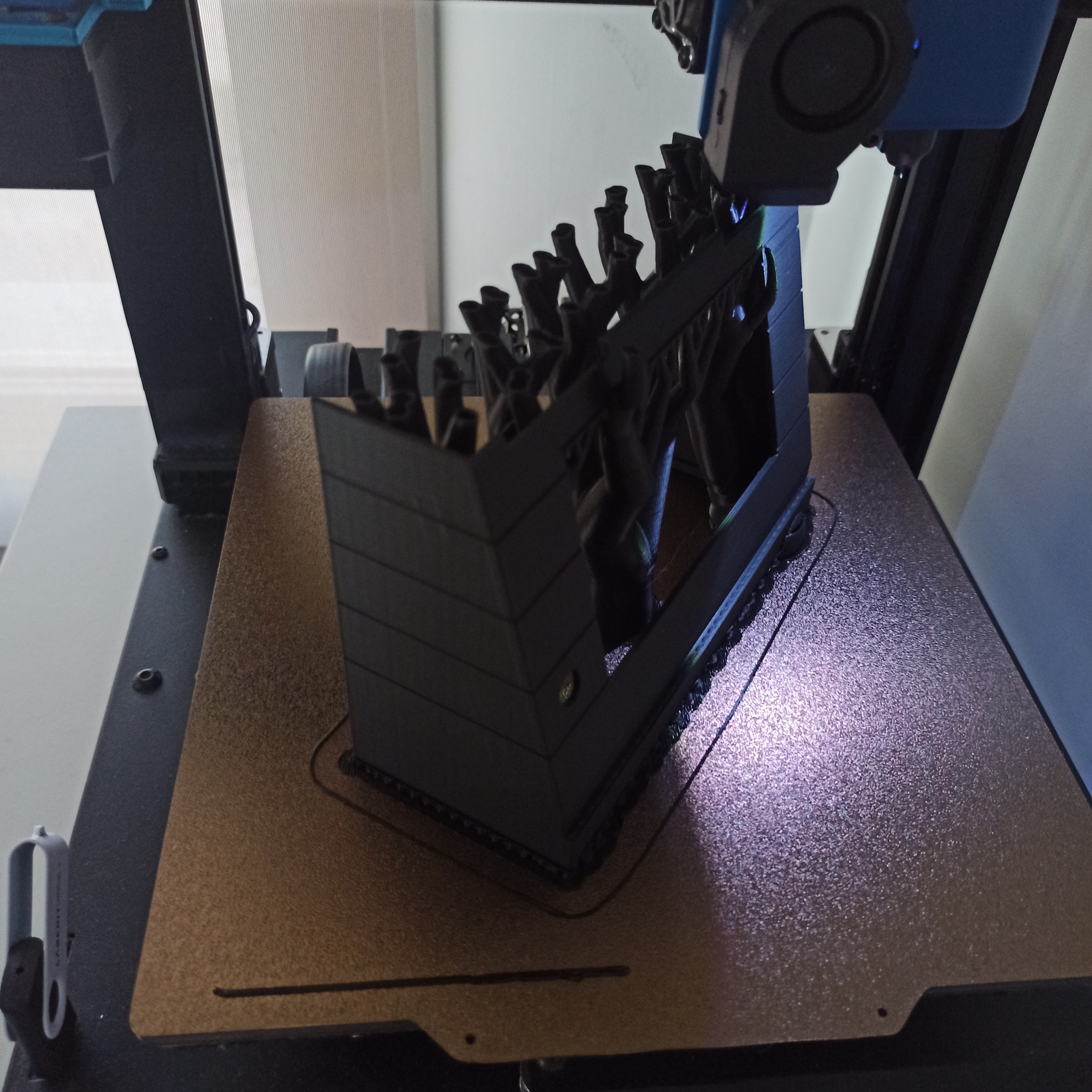
Print all parts. I have printed them all oriented towards z and with organic supports. With 0.4 nozzle, 0.2 layers and 30% filling. Except on the keys and small elements I have isated layer of 0.12
![]()
![]()
-
2Step 2
Insert the M4 and M3 nuts with a fine wire soldering iron. There are 4 of M4 on the base to fix the keyboard and another 4 between the structure and the back cover. And finally 4 of M3 on the base to fix the orange pi zero2 card
-
3Step 3
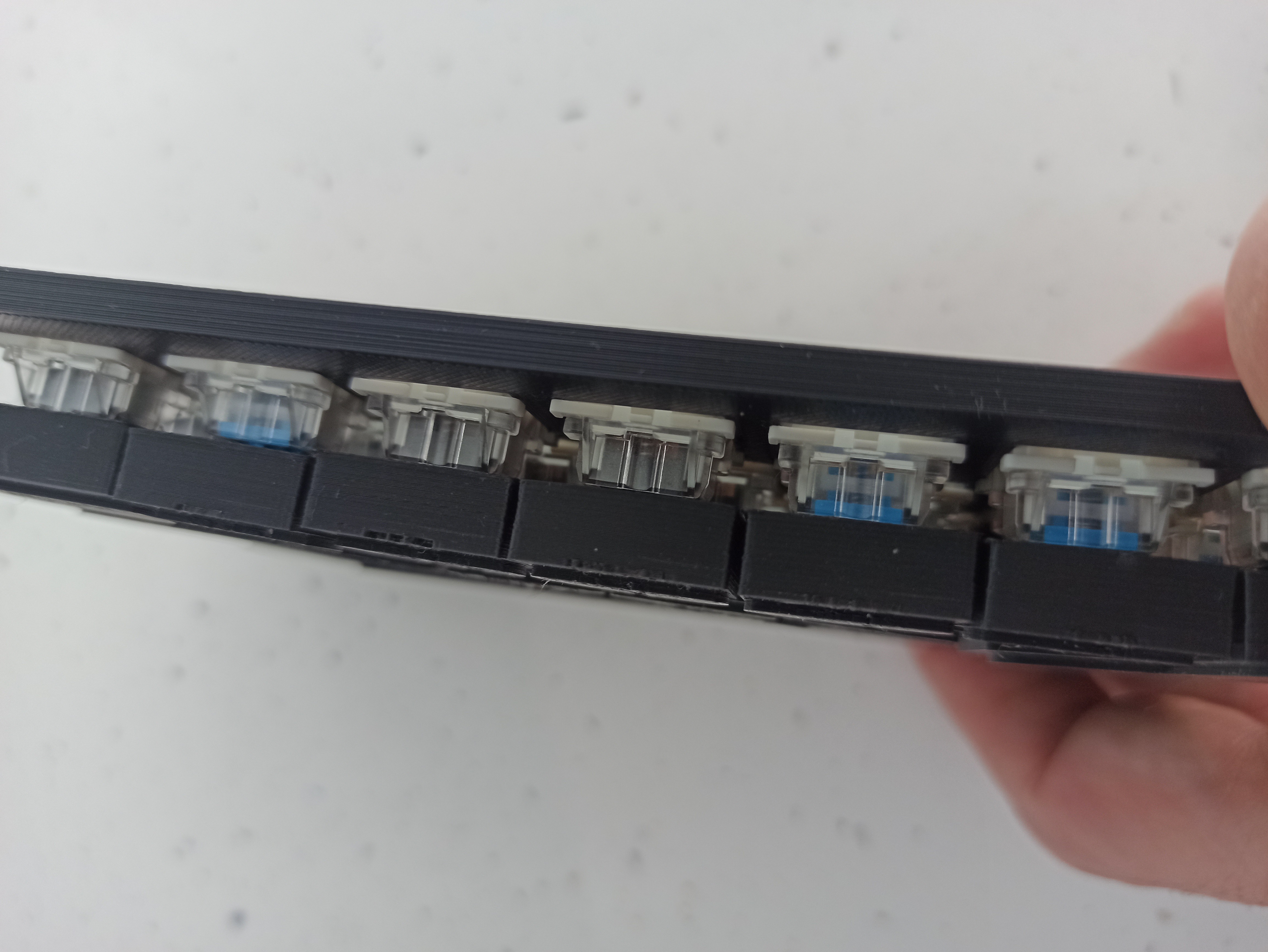
Assemble all the keys and fix them in the matrix to later solder joining all the negatives. Next, solder a male dunpot wire to each key. When we do the assembly, the terminals will end up in the inputs of the Arduino pro micro
![]()
![]()
![]()
-
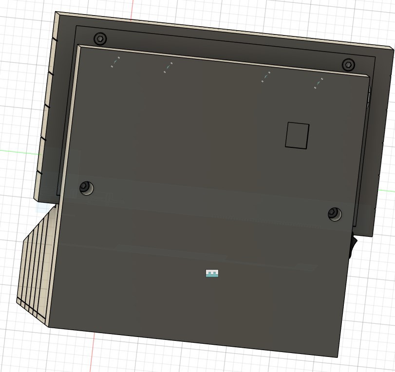
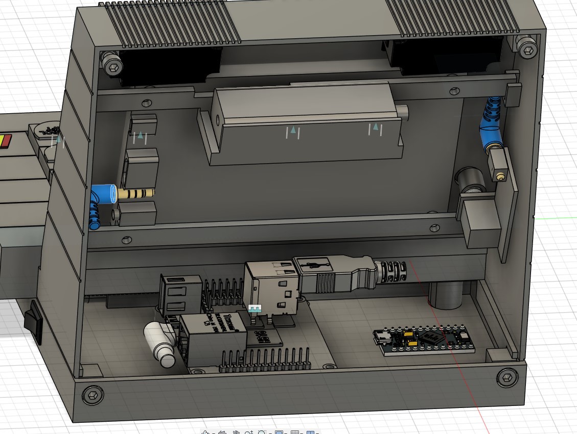
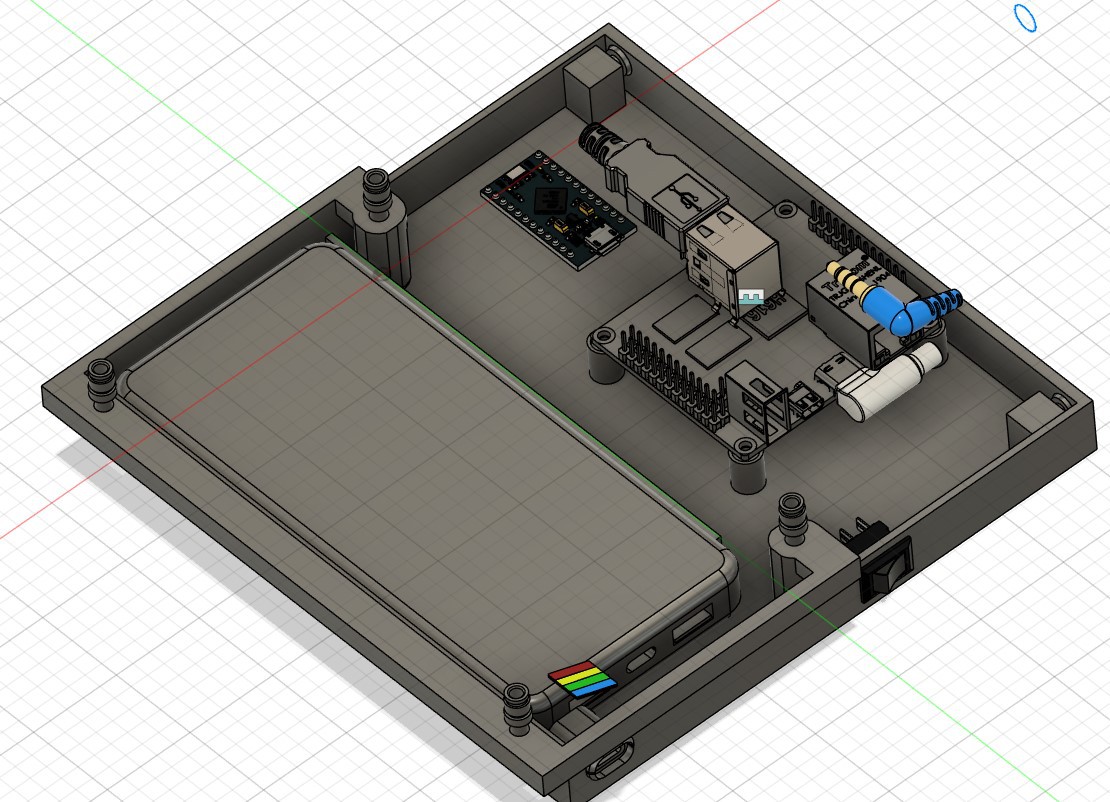
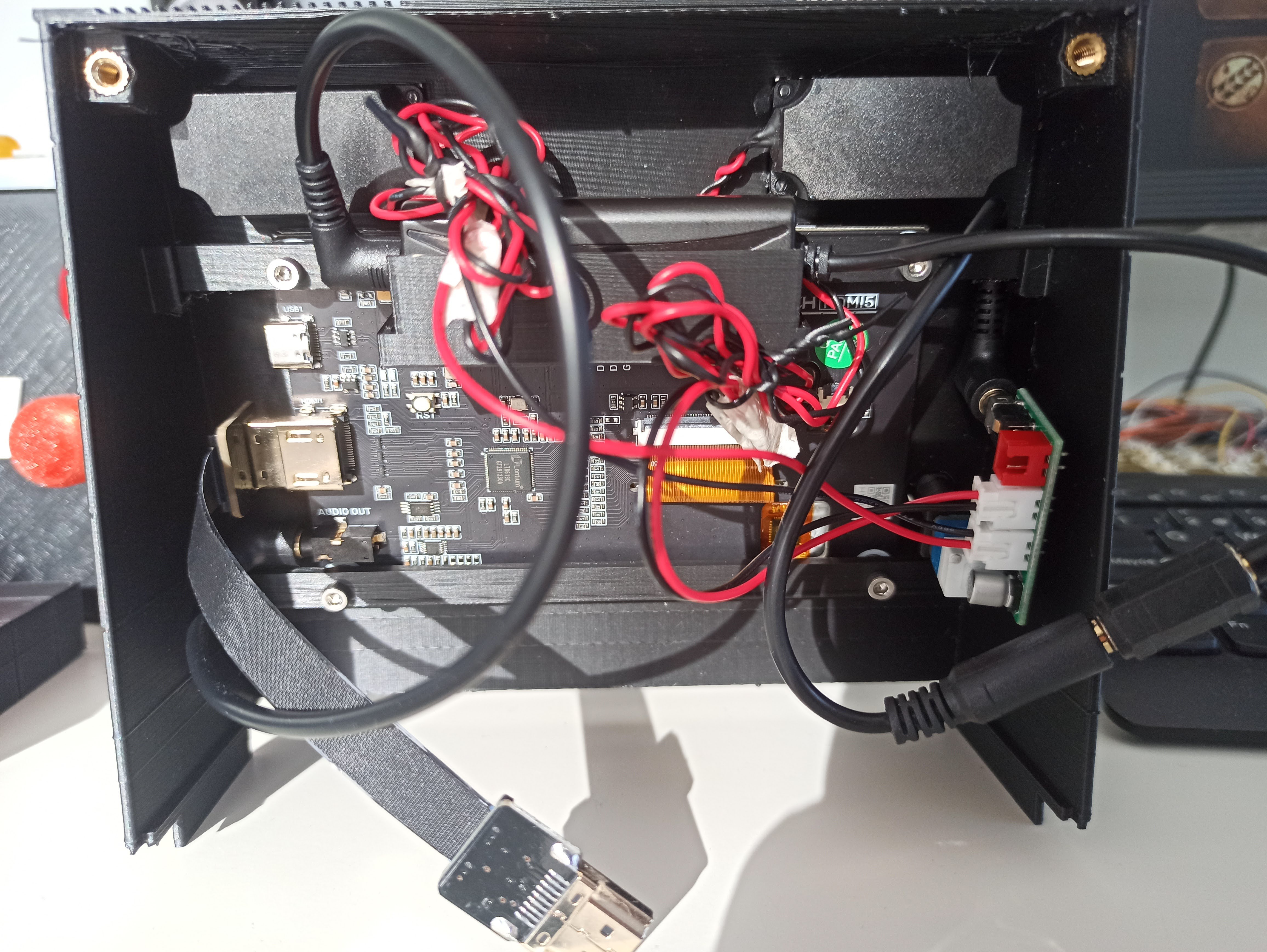
4Step 4
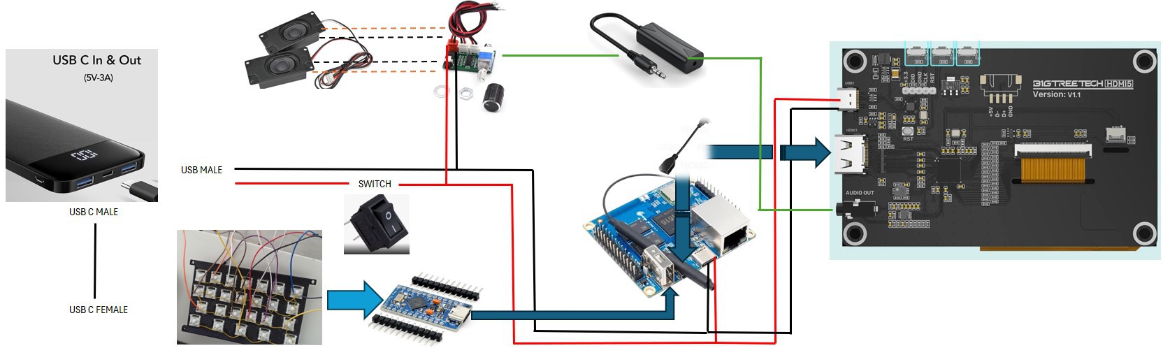
We arrange the components on the printed parts and with the help of a soldering iron and the listed components we connect the devices.
![]()
-
5Step 5
The entries defined in the ino file for the arduino are the following:
const int Pin_ButtonA = 4;
const int Pin_ButtonB = 5;
const int Pin_ButtonX = 6;
const int Pin_ButtonY = 7;const int Pin_ButtonLB = 8;
const int Pin_ButtonRB = 9;const int Pin_ButtonBack = 14;
const int Pin_ButtonStart = 10;const int Pin_ButtonL3 = 2;
const int Pin_ButtonR3 = 3;const int Pin_ButtonL2 = 21;
const int Pin_ButtonR2 = 20;// Directional Pad Pins
const int Pin_DpadUp = 15;
const int Pin_DpadDown = 16;
const int Pin_DpadLeft = 18;
const int Pin_DpadRight = 19;![]()
-
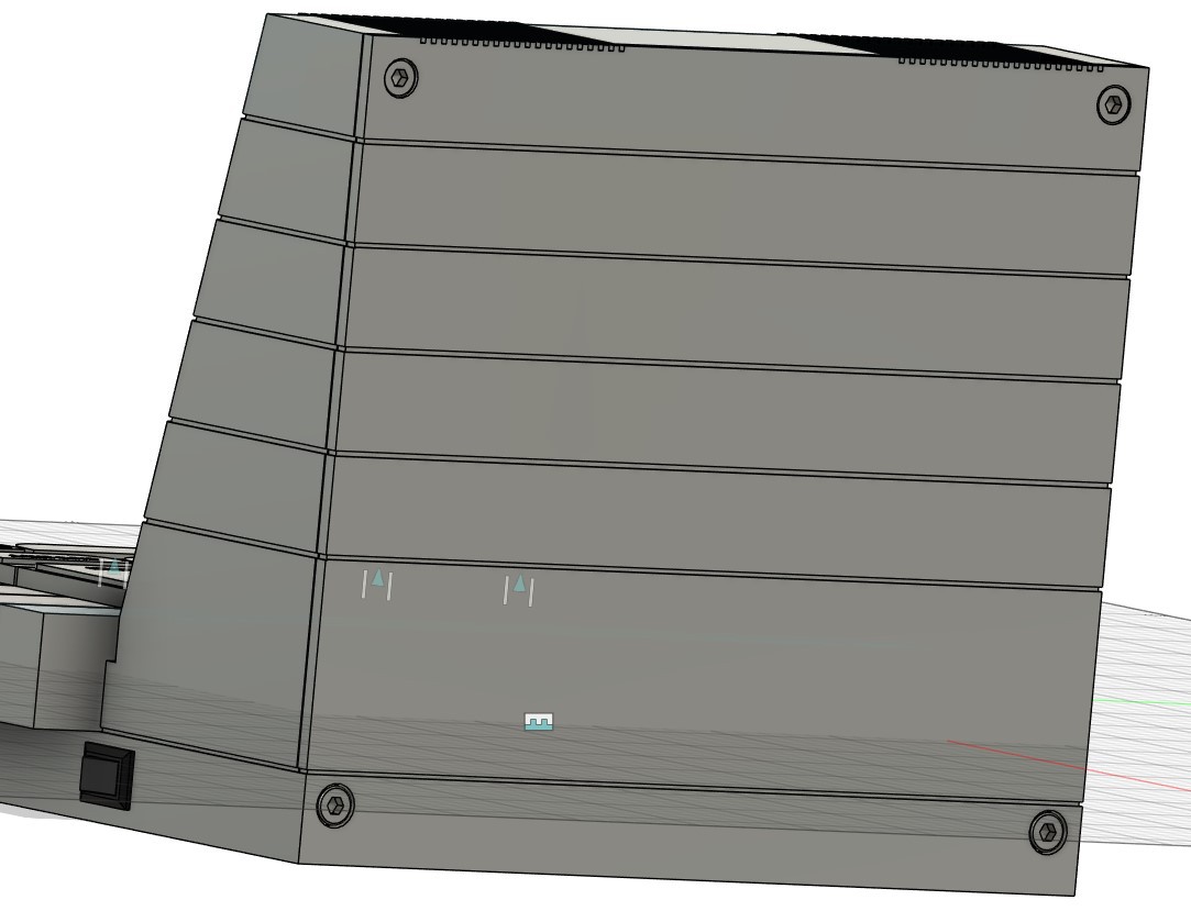
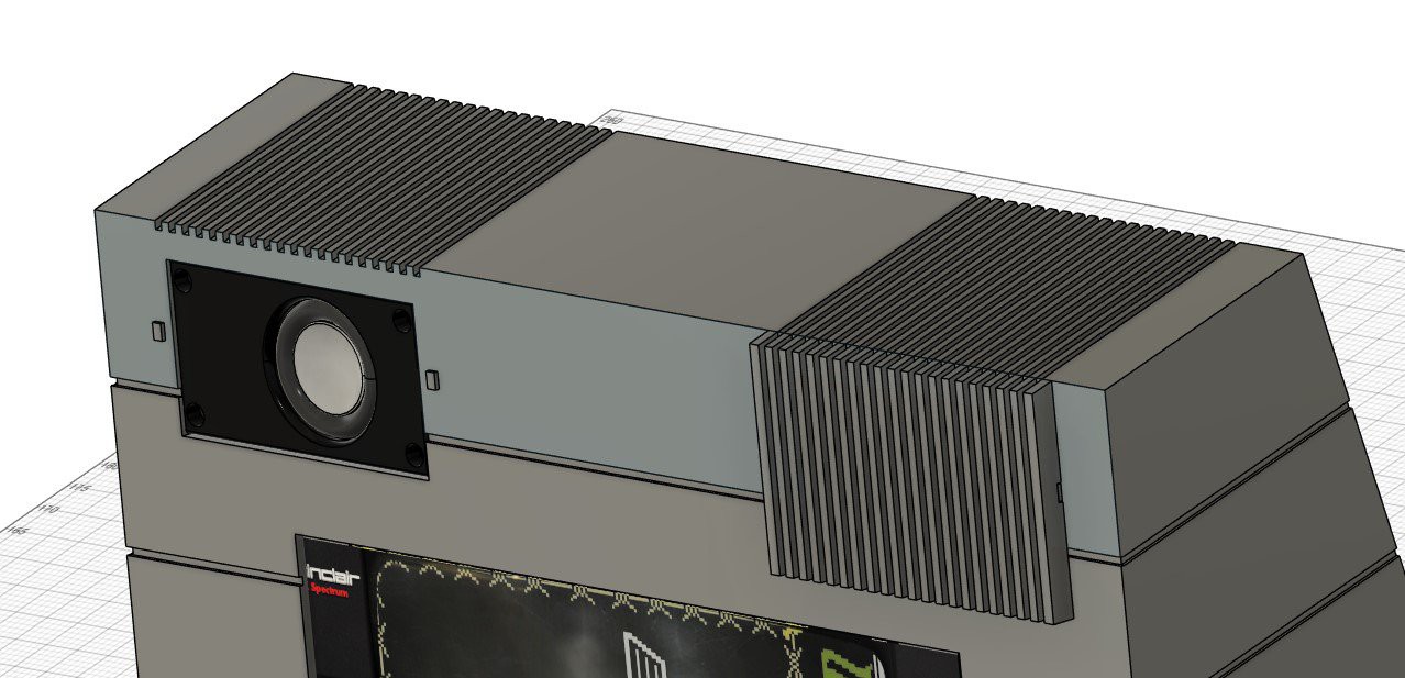
6Step 6
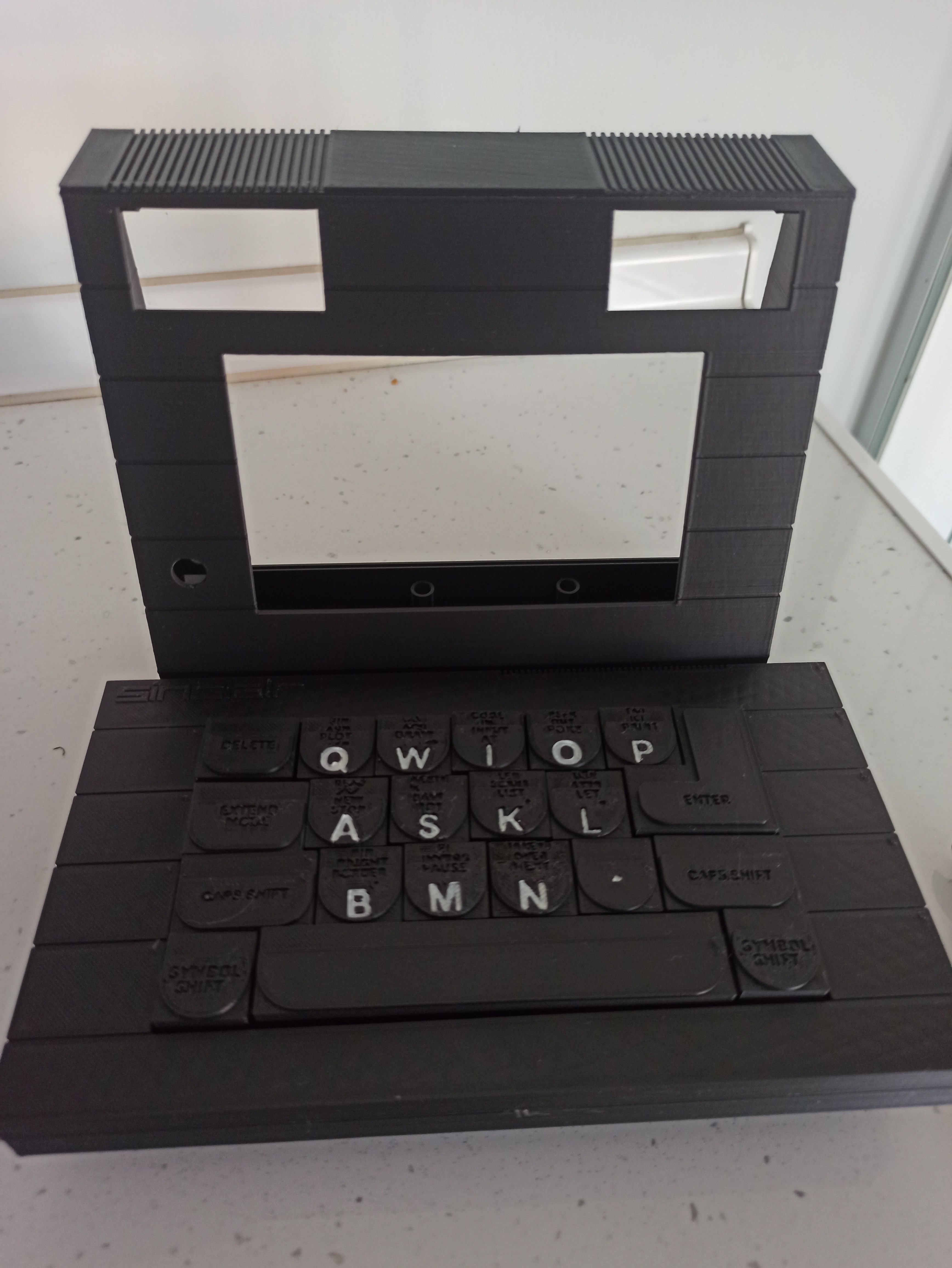
We only have to finish the assembly, screwing all the elements. To fix the upper part that contains the screen and the base I used extra strong glue. I have also used it to fix the speakers and their respective grills. And finally the head of the volume thread.
![]()
![]()
![]()
![]()
![]()
![]()
-
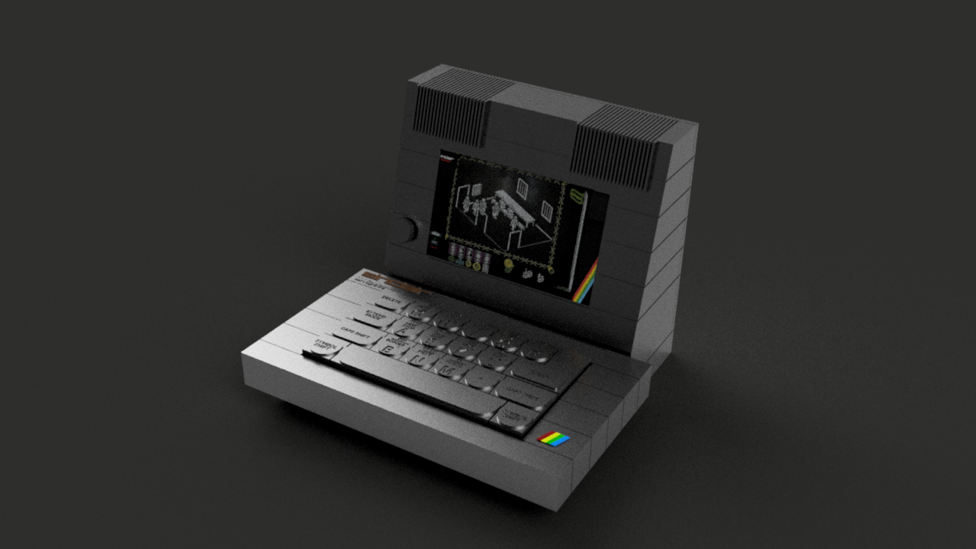
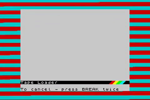
7Step 7
Finally we have to record the image based on batocera. Whose compilation and control mapping comes from the wonderful BOB multi-system image. I have change the images and music related to spectrum look
![]()
![]()
MICRO SPECTRUM +
Design and creation of a Spectrum + micro. Designed for 3D printing, based on an orange pi zero2. 5" screen, mechanical keyboard, 3w ampli.


Discussions
Become a Hackaday.io Member
Create an account to leave a comment. Already have an account? Log In.