Close
0%
0%

Master Chief Light Board

Constructed an RGB Master Chief Light Board to be installed in a PC for aesthetic purposes.

Public Chat
Similar projects worth following
0 followers
Greetings to everyone, and welcome back.

Here's something super cool: a Master Chief RGB Light Board made completely from scratch using custom PCBs and an XIAO ESP32S4 DEV Board.
Master Chief is a central character in the popular game series "Halo." He is a genetically enhanced super-soldier known formally as John-117. Master Chief serves as the protagonist throughout most of the series.

The goal was to create an RGB light that would be aesthetically pleasing enough to be installed inside a PC to enhance its appearance. This board is visible via the PC's side glass panel.

The device is powered by a USB Type C cable, which is connected to the back USB port of the motherboard.

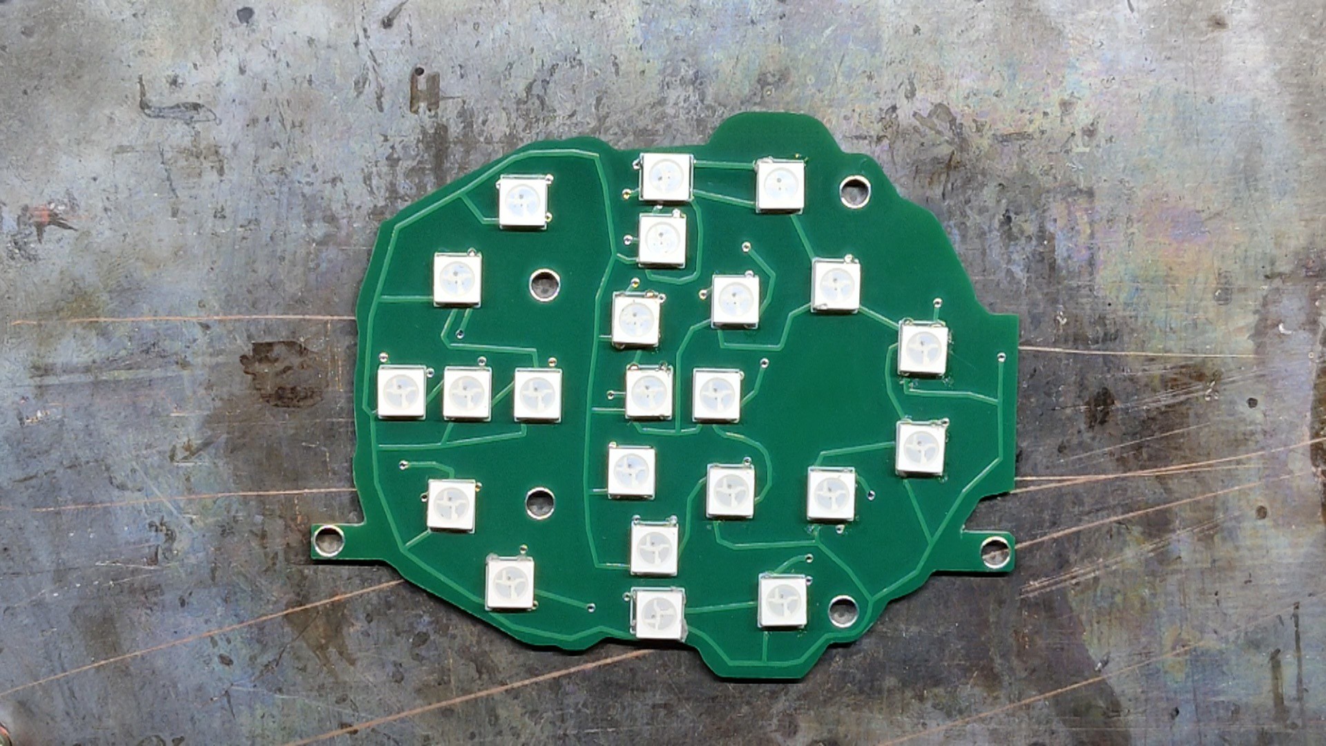
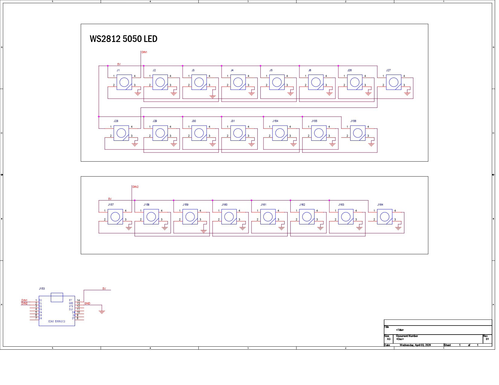
24 WS2812B LEDs were used in this project, paired with an XIAO ESP32S4 Dev board.

PCB Design

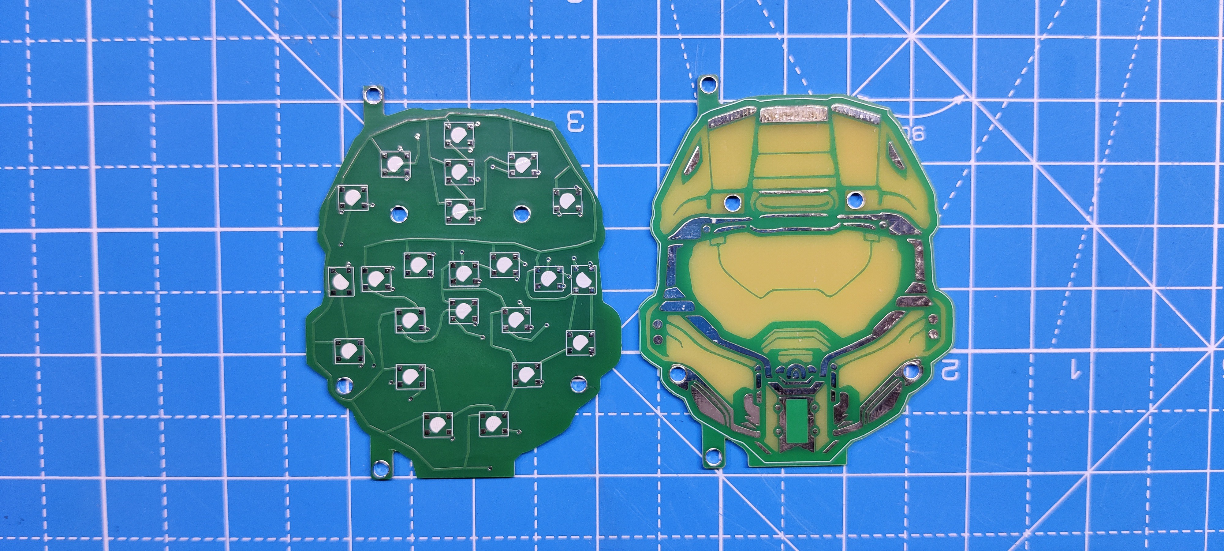
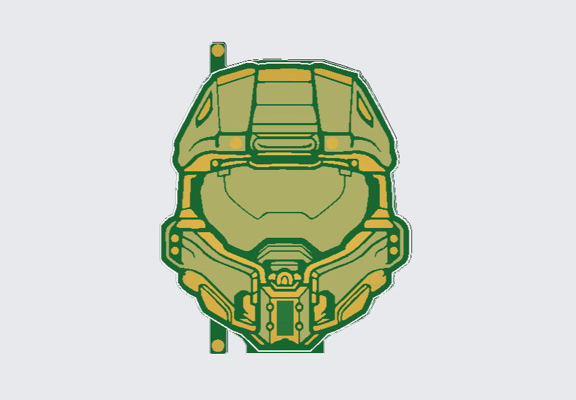
The PCB design for this project was split into two parts: the top layer board, or first board, which is just made up of solder mask opening layers, and a silkscreen that was themed after the helmet of the master chief.

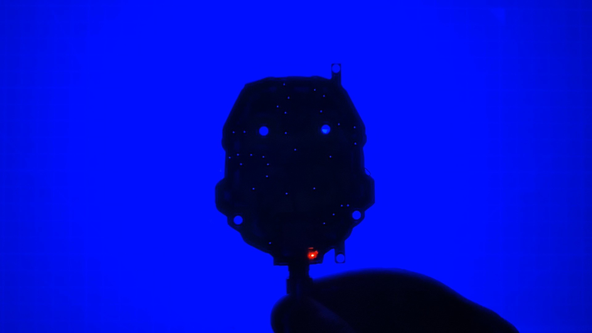
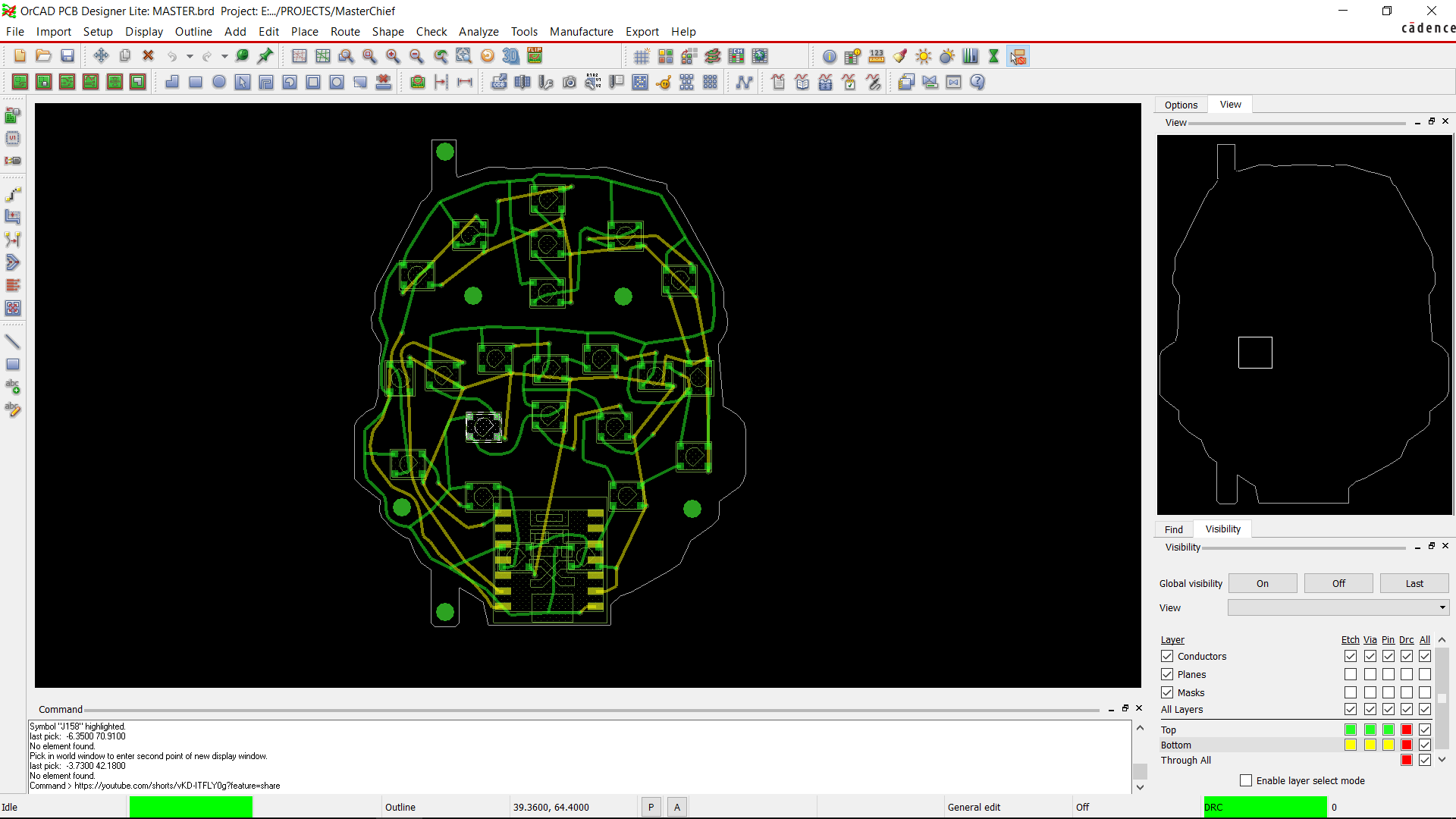
The RGB LEDs and XIAO MCU are positioned on the second, or bottom, board. The RGB LEDs' glow is visible through the top PCB's solder mask opening.

We first looked for a black and white picture of Masterchief's helmet to use for the first layer, and we found one that will work perfectly.

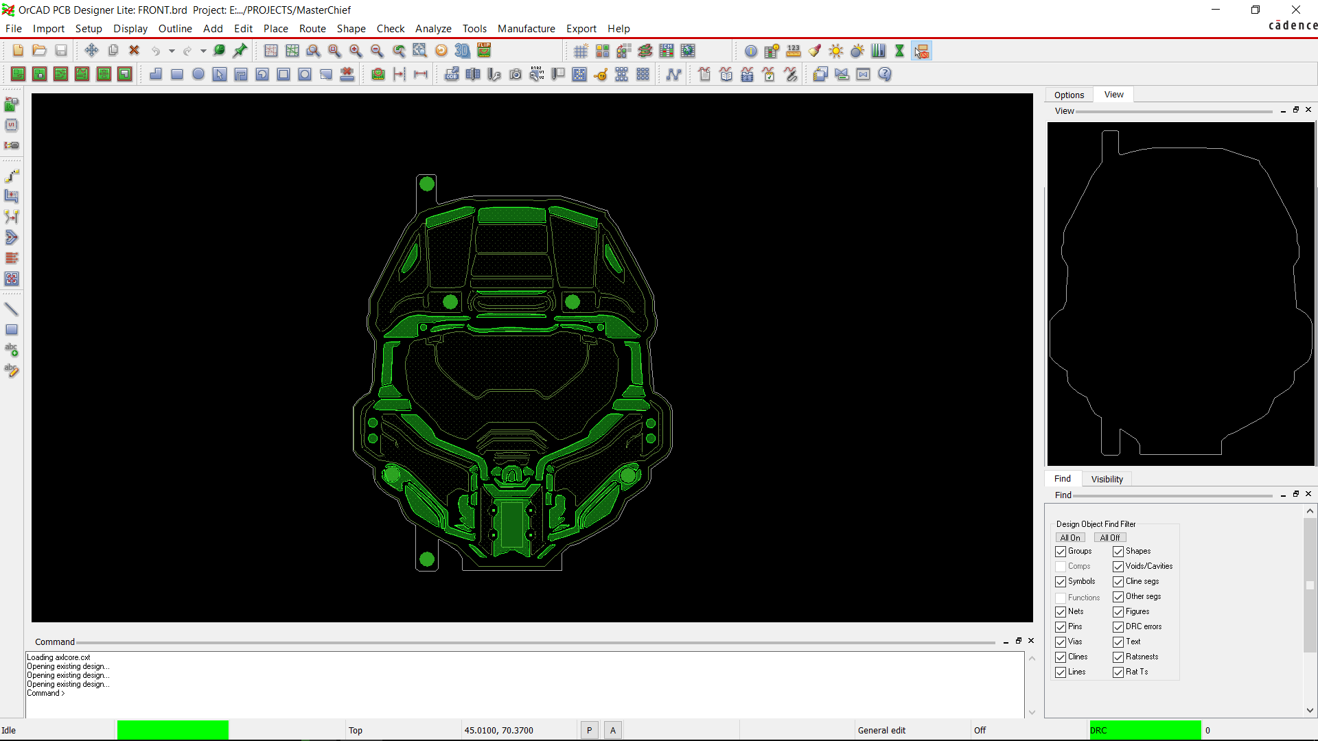
We converted the image into BMP as we're using OrCad Cadence, which only imports logo files as BMP images.

After adding the basic image inside the CAD software, we added a top-etch layer by tracing out the helmet outlines. After that, we add a soldermask opening on top of the etch layer, which exposes the empty FR4 board along with the etch layer.

The etch layer, when exposed, will look silver or gold depending on the PCB surface finish, which in our case will be HASL or silver.

We added a soldermask opening on the bottom side as well, so light can easily transfer through the PCB.

For the second PCB, or bottom board, we first prepare a schematic consisting of 24 WS2812B LEDs connected together with the XIAO ESP32S4 DEV Board.

We then positioned the RGB LEDs on the second board's top face, and XIAO is positioned on the bottom face.

Seeed Studio Fusion Service
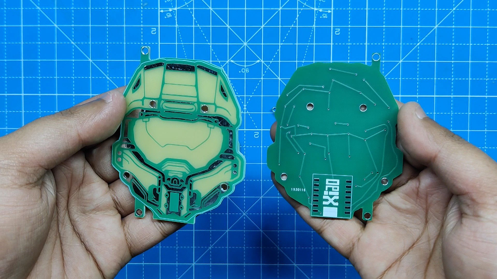
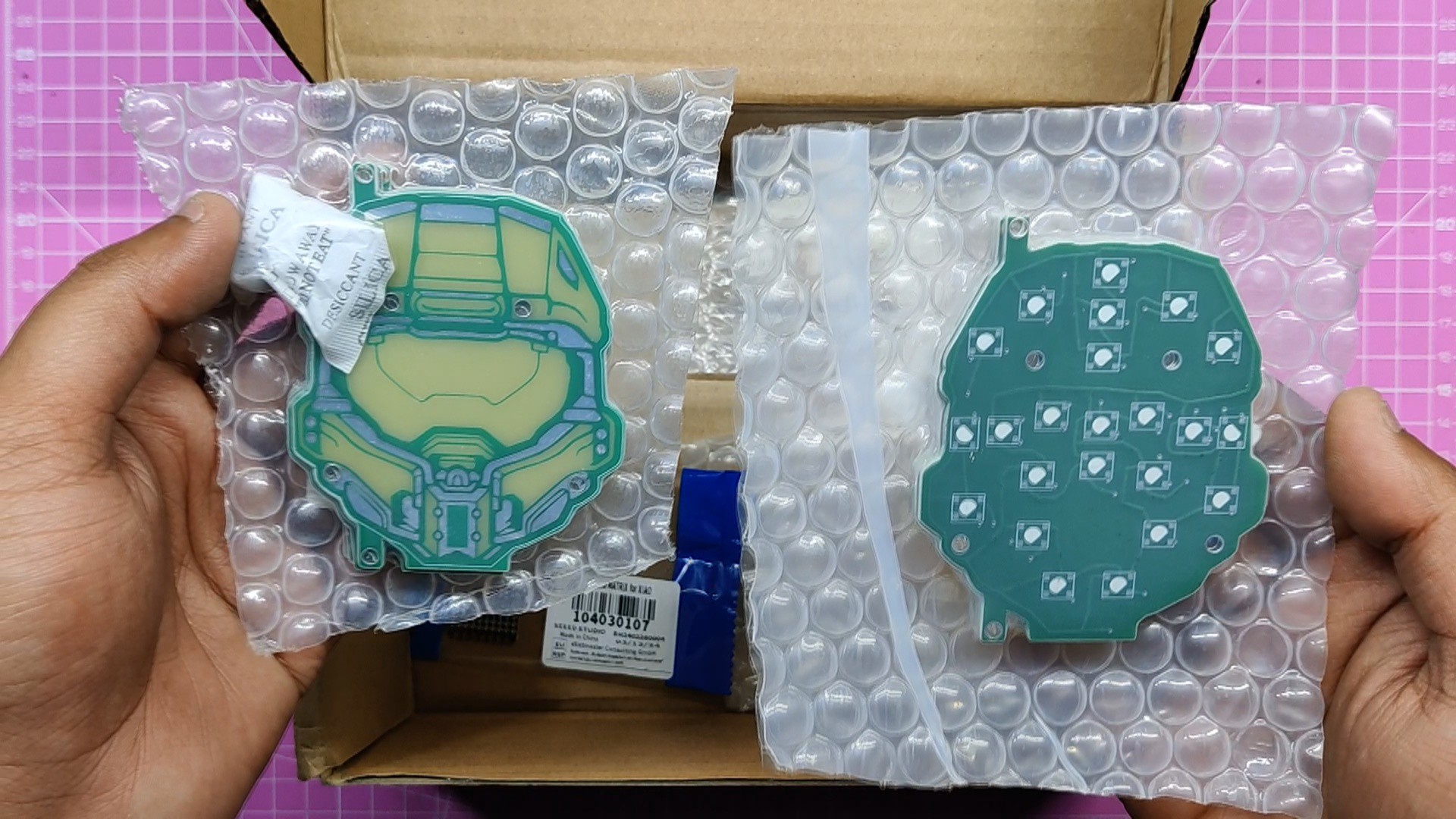
After finalizing both PCBs, we exported their gerber data and sent them to Seeed Studio Fusion for samples.

Two orders were placed, one for the front board and one for the back board; both orders were placed in a green soldermask and white silkscreen.

PCBs were received in a week, and their quality was super good considering the rate, which was also pretty low.

Seeed Fusion PCB Service offers one-stop prototyping for PCB manufacture and PCB assembly, and as a result, they produce superior-quality PCBs and fast turnkey PCBAs within 7 working days.

Seeed Studio Fusion PCB Assembly Service takes care of the entire fabrication process, from Seeed Studio Fusion Agile manufacturing and hardware customization to parts sourcing, assembly, and testing services, so you can be sure that they are getting a quality product.

After gauging market interest and verifying a working prototype, Seeed Propagate Service can help you bring the product to market with professional guidance and a strong network of connections.

LED BOARD.rar

RAR Archive - 15.31 kB - 05/13/2024 at 17:38

Download

front.rar

RAR Archive - 29.40 kB - 05/13/2024 at 17:38

Download

SCH.pdf

Adobe Portable Document Format - 170.70 kB - 05/13/2024 at 17:38

Preview

  • 1
    PCB Assembly
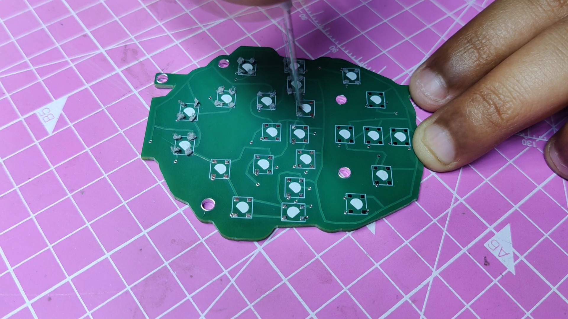
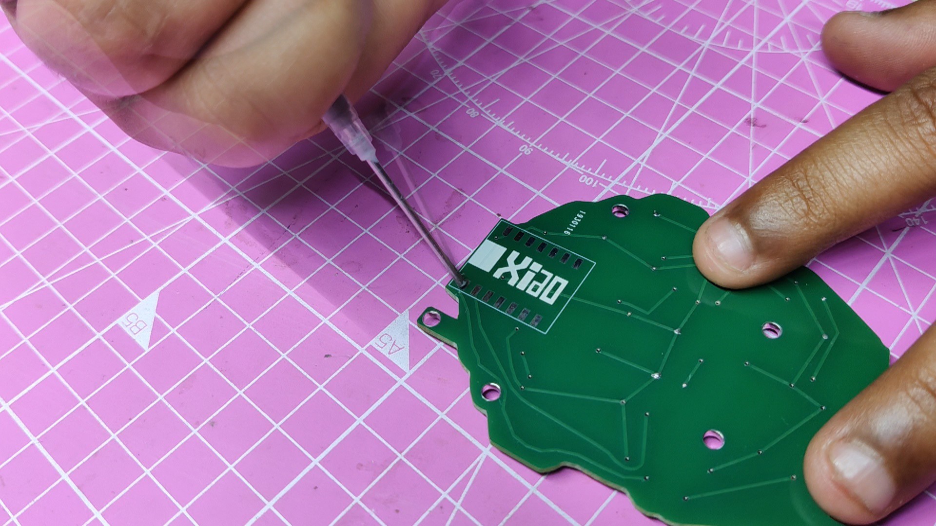
    • Using a solder paste dispensing needle, we first add solder paste to each component pad, one by one. We're using standard 37/63 solder paste here.
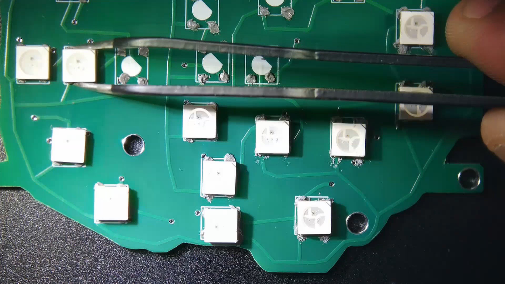
    • Next, we pick and place all the SMD components in their places on the PCB using an ESD tweezer.
    • With extreme caution, we lifted the complete circuit board and placed it on the SMT hotplate, which increases the PCB's temperature to the point at which the solder paste melts and all of the components are connected to their pads
  • 2
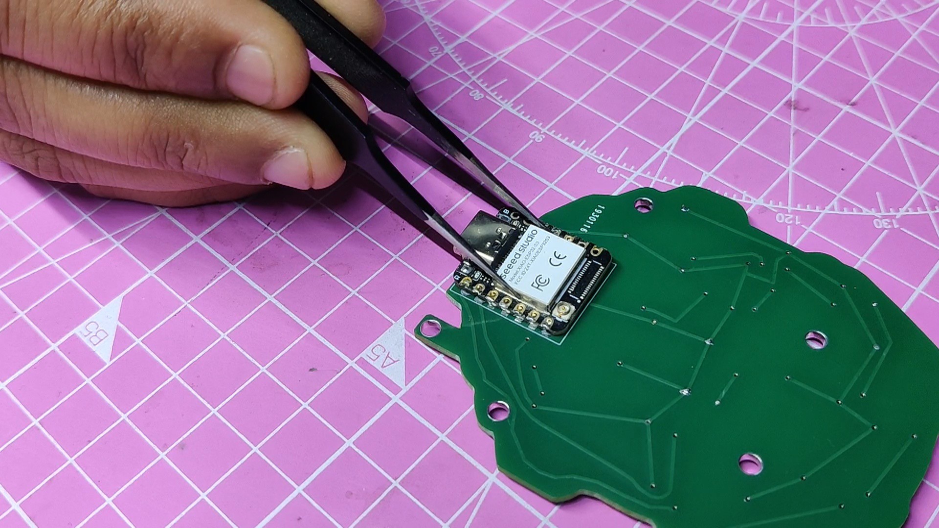
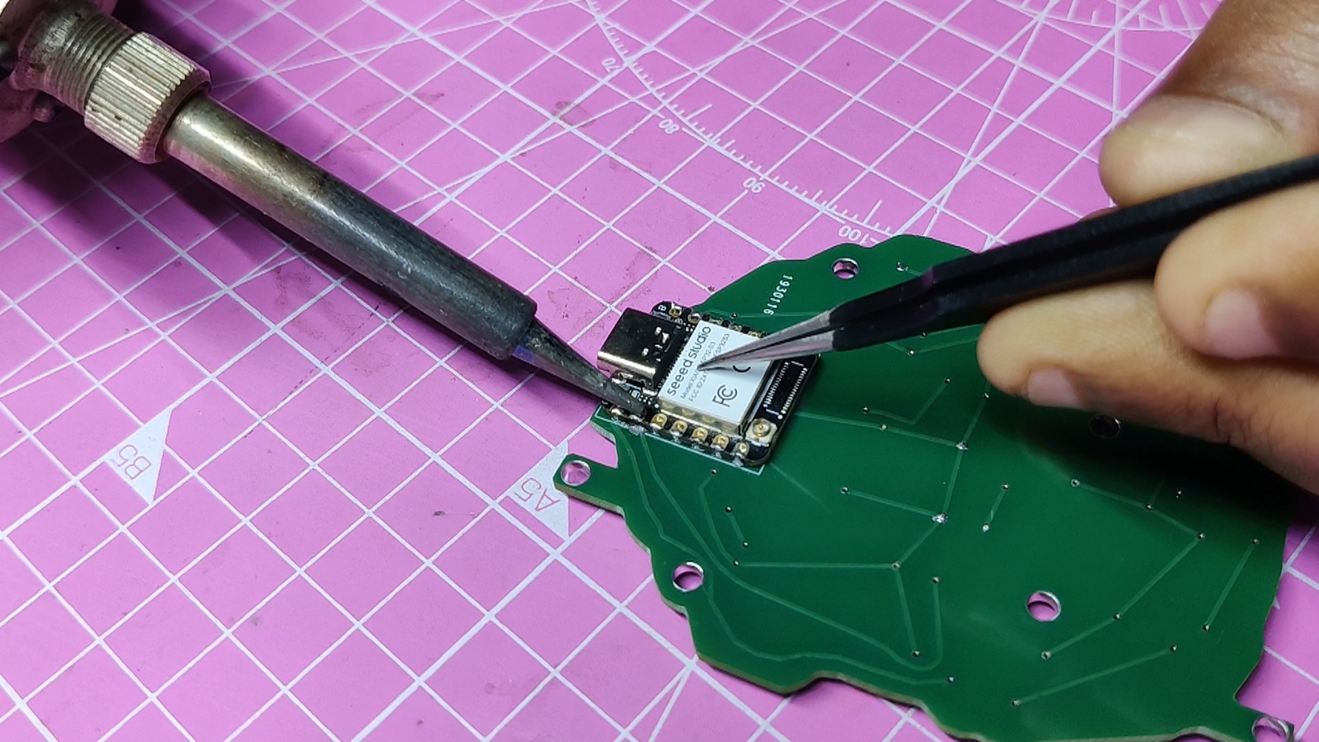
    Adding XIAO on bottom side

    The XIAO has to be installed on the bottom side using the surface mount method after the LEDs are added to the top side. One tiny problem: the led on the bottom of this prevents us from using a reflow hotplate.

    An approach is to use solder paste on the pads of the component before picking and placing it in its proper location.

    The PCB is then soldered in place after the connector pins on the component are heated using a soldering iron to melt the solder paste underneath the pads.

  • 3
    Main Code

    We first check to see if the LEDs were soldered correctly after the PCB assembly process. We employ a straightforward test code that sequentially turns on each LED in the sequence.

    #include <Adafruit_NeoPixel.h>
    #ifdef __AVR__
     #include <avr/power.h> // Required for 16 MHz Adafruit Trinket
    #endif
    
    // Which pin on the Arduino is connected to the NeoPixels?
    #define PIN       D1 // On Trinket or Gemma, suggest changing this to 1
    
    // How many NeoPixels are attached to the Arduino?
    #define NUMPIXELS 25 // Popular NeoPixel ring size
    
    // When setting up the NeoPixel library, we tell it how many pixels,
    // and which pin to use to send signals. Note that for older NeoPixel
    // strips you might need to change the third parameter -- see the
    // strandtest example for more information on possible values.
    Adafruit_NeoPixel pixels(NUMPIXELS, PIN, NEO_GRB + NEO_KHZ800);
    
    #define DELAYVAL 100 // Time (in milliseconds) to pause between pixels
    
    void setup() {
      // These lines are specifically to support the Adafruit Trinket 5V 16 MHz.
      // Any other board, you can remove this part (but no harm leaving it):
    #if defined(__AVR_ATtiny85__) && (F_CPU == 16000000)
      clock_prescale_set(clock_div_1);
    #endif
      // END of Trinket-specific code.
    
      pixels.begin(); // INITIALIZE NeoPixel strip object (REQUIRED)
    }
    
    void loop() {
      pixels.clear(); // Set all pixel colors to 'off'
    
      // The first NeoPixel in a strand is #0, second is 1, all the way up
      // to the count of pixels minus one.
      for(int i=0; i<NUMPIXELS; i++) { // For each pixel...
    
        // pixels.Color() takes RGB values, from 0,0,0 up to 255,255,255
        // Here we're using a moderately bright green color:
        pixels.setPixelColor(i, pixels.Color(0, 150, 0));
    
        pixels.show();   // Send the updated pixel colors to the hardware.
    
        delay(DELAYVAL); // Pause before next pass through loop
      }
    }

     After testing the LEDs, we uploaded the main code into the XIAO MCU.

    #include <Adafruit_NeoPixel.h>
    
    #define GREEN_LED_PIN D0
    #define PURPLE_LED_PIN D1
    #define NUM_LEDS 15 // Number of LEDs in each strip
    
    Adafruit_NeoPixel greenLED = Adafruit_NeoPixel(NUM_LEDS, GREEN_LED_PIN, NEO_GRB + NEO_KHZ800);
    Adafruit_NeoPixel purpleLED = Adafruit_NeoPixel(NUM_LEDS, PURPLE_LED_PIN, NEO_GRB + NEO_KHZ800);
    
    void setup() {
      greenLED.begin();
      purpleLED.begin();
    }
    
    void loop() {
      // Set green LED to green color (RGB: 0, 255, 0)
      greenLED.setPixelColor(0, greenLED.Color(0, 255, 0));
      greenLED.show();
    
      // Set purple LED to purple color (RGB: 128, 0, 128)
      purpleLED.setPixelColor(0, purpleLED.Color(128, 0, 128));
      purpleLED.show();
      
      delay(1000); // Delay for 1 second
    }

View all 6 instructions

Enjoy this project?

Share

Discussions

Similar Projects

Does this project spark your interest?

Become a member to follow this project and never miss any updates