I managed to get it to work with a monitor using my #RA8875 VGA card, and it is working rather well:
I'm getting around 20-30 FPS, depending on where I point the camera. With the RA8875, I can use 8-bit color, so the colors look a lot better than have previously been shown on this project. The cost, is that there is no longer any transparency, but this isn't noticeable yet. It took me a bit to get the new color system working, so the above picture is taken after I fixed the color issues, but the video below does not have them fixed yet. It was related to how the color data is saved on the SD card to make it easier to load.
The second half of the video largely just describes how the rendering engine works - if you follow this project, then you probably already know it. The main thing I've done is port my #NTIOS (Arduino OS) RA8875 driver to the Arduino Minecraft codebase - I'm not using NTIOS for this project because I need to keep resource consumption to an absolute minimum for this limited hardware.
I changed the screen resolution to 400x300 for now, but this significantly impacts the framerate. This is fine, as I'm just running some tests for now. First, I needed to fix the texture rendering. The math I was using before was very monkey, and needed to be changed. There is some code used to check if a given pixel is inside each rendered quad, and this generates some coefficients. These coefficients apply to the edges, not vertices, however. I found that it wasn't hard to do some linear transformations to extract the texture coordinates, and actually the new math is faster than the original code. I also made grass have a different texture for the top; and now we have this rendering: This is much better. The quads in this image are diamond shaped and rotated, but the textures are almost perfect! The shape of the terrain isn't too hard to make out, and with a more interesting scene, it could probably look a lot cooler. We do see nearby textures bleeding into the dirt texture though. To fix this, we can add a simple if block to prevent the texture coordinates from going out of bounds. Certainly, this can't affect our render time much. Certainly... right?
At this point I was doing some profiling to see what's eating up my CPU time. The first thing I wanted to know was the overhead of the map floodfill algorithm; turns out it's really tiny. I knew it wouldn't be more than half, but I had no idea it would be this small:
Processed 1035 blocks of 16384 total blocks.
Total time: 43.820000ms
Render time: 43.351000ms
Time taken for 100 frames: 4412ms
Time per frame: 44120.000us
FPS: 22.7
Less than half a millisecond - ore just more than 1% of the render time. About 98.5% of the render time is spent on the 3D rendering code, and of that probably about 99% is spent on computing and drawing individual pixels - not even matrix multiplication or any actual 3D projection. Ok, so let's see how much time we add by just adding some if blocks to check the texture coordinates:
// Almost all textures tile well.if (kx > 1) kx -= 1;
elseif (kx < 0) kx += 1;
if (ky > 1) ky -= 1;
elseif (ky < 0) ky += 1;
Processed 1035 blocks of 16384 total blocks.
Total time: 46.214000ms
Render time: 45.750000ms
Time taken for 100 frames: 4652ms
Time per frame: 46520.000us
FPS: 21.5
That's a big increase, considering its a simple if block. The reason is that the fragment code does an unbelievable number of iterations, so that if block is probably running millions of time per frame. All together the if block adds about 2.39ms, or 5%. That's a lot when you need less than 16ms for 60FPS. If a simple if block like that adds that much time, then what about the other if blocks in the fragment code?
inlinevoidfragmentShaderRaw(DisplayBuffer* display, int x, int y, uint8_t z, Color textureColor){
uint32_t displayIndex = display->width * y + x;
uint8_t* depthLoc = &(display->depthArray[displayIndex]);
if (*depthLoc < z)
// Discard the fragmentreturn;
if (textureColor >> 4 == 0)
// The fragment has no color; discard.return;
Color fragColor = textureColor;
// Apply this fragment to the framebuffer
Color* outColor = &display->colorArray[displayIndex];
if (fragColor >> 4 == 15)
*outColor = fragColor;
else {
*outColor |= fragColor;
*outColor &= 0x7;
}
*depthLoc = z;
}
So now, looking at this simple and rather streamlined function, we can see that in reality it takes a lot of time. Most of these checks cannot be avoided. However, I was able to optimize a lot of my quad drawing function, which did a lot of the same math many times in a tight loop. I found that each multiplication I removed saved me about half a millisecond! Here is my timing now, under the same test: This is much better, especially for the higher resolution of 300x400.
It is worth noting that, for these tests, the processor is running at 720Mhz. This is about a 20% overclock. Here are the stats at different processor speeds - you could probably calculate this but a table is convenient:
Clock Speed
Frame Time
FPS
600Mhz
45.85
21.6
720Mhz
38.2ms
26.0
816Mhz
33.71
29.4
912Mhz
30.16ms
32.9
960Mhz
28.66ms
34.6
Some of these chips go as high as 1.08 Ghz. Other chips I have can't go above 600Mhz. So there really is a chip lottery with the Teensy 4.1s. The chip I was testing with here started crashing at 1.08Ghz, so I did not put that speed in the table. In any case, it is promising that the speeds are this good at that resolution.
I can render some of the terrain's shape, but the texture coordinates are not handled properly, and I can currently only render one chunk. This is the first part for getting the rendering to do what I want, after this I need to:
Optimize the code more and fix the texture bugs, and ensure it works for more scenarios (Part 2)
Expand it to handle multiple 16x16x64 chunks (Part 3)
Block Iteration Speed - How to Render Voxels Fast
I don't have screenshots, but originally my render for a whole chunk took over a second - so entirely unplayable. This was for two reasons:
My naive loop that iterates over every block in the chunk, checks if it is covered by other blocks, and renders if not
Rendering the sides of chunks
It was easy to make the chunk sides not render. We don't want this because the player should never see the sides anyway - they would simply enter a new chunk. I think this was the bulk of it, because when I switch to the loop again, it now only takes 82ms to render. That's a 90%+ speed boost.
The harder part was eliminating the loop. How do you render the blocks without checking each one? Well, all the blocks that need to be rendered have two things in common. First, they all occur within the camera's view. Second, they all touch the same connected region of air. By using something akin to a floodfill algorithm, we can find only blocks visible to the player, and ignore about 90% of the blocks in the chunk - never even iterating over them.
A floodfill algorithm has expensive overhead, especially when considering the need to check the camera's viewport, which involves two matrix multiplications for every block. However, to iterate over every block in the chunk, it is 16x16x64 iterations, or 16384 iterations. For many blocks that aren't visible, this may cause rendering, and even for non-rendered blocks, it involves a series of checks for rendering. This is especially true of caves. So, it is much better never to iterate over those blocks at all. The overhead for the floodfill algorithm, as it turns out, is well worth it.
My floodfill algorithm processed only 1140 blocks, or 7% of the 16384 blocks in the chunk. It isn't perfect and probably has a bug or two, but still this is very pleasing.
The algorithm is a modified Breadth-First-Search. Here's the code:
// This essentially checks if the block is in the camera's viewboolisValidNode(int x, int y, int z){
Vector3 pos = { x, y, z };
applyMat4fToVertex(&pos, &(settings.worldMatrix));
pos.z += 0.5f;
if (pos.z > 0 && pos.z < 0.1f)
pos.z = 0.1f;
float k = 1 / pos.z;
pos.x = (pos.x + (pos.x < 0 ? 0.5f : -0.5f)) * k;
pos.y = (pos.y + (pos.y < 0 ? 0.5f : -0.5f)) * k;
applyMat4fToVertex(&pos, &settings.projectionMatrix);
return pos.z >= 0 && pos.z < 260 && pos.x >= 0 && pos.y >= 0 && pos.x < width && pos.y < height;
}
voidsearchRender(uint8_t blocks[16][16][64], uint8_t camx, uint8_t camy, uint8_t camz){
// This function does a breadth-first search, where the graph's nodes are every block within the camera's viewport.// x, y, and z are the coordinates to start the search at.Vector3iQueue queue(128);
uint16_t searchedBlocks[16][64];
bzero(searchedBlocks, 16*64*2);
queue.append(camx, camy, camz);
int blocksProcessed = 0;
uint8_t x, y, z;
while (queue.get(x, y, z)) {
// Fill it.for (uint8_t q = 1; q < 64; q*=2) {
uint8_t i = x + ((q >> 0) & 1) - ((q >> 3) & 1);
uint8_t j = y + ((q >> 1) & 1) - ((q >> 4) & 1);
uint8_t k = z + ((q >> 2) & 1) - ((q >> 5) & 1);
// Skip blocks outside this chunkif (i & 0xF0 || j & 0xF0 || k & 0x80)
continue;
// Mark the block as checkedif ((searchedBlocks[j][k] >> i) & 1)
continue;
searchedBlocks[j][k] |= 1 << i;
blocksProcessed++;
// Check if the block is in view:if (!isValidNode(i, j, k))
continue;
// Should we render it, or fill it?uint8_t block = blocks[i][j][k];
if (block > 0)
renderBlock(i, j, k, block);
elsequeue.append(i, j, k);
}
}
Serial.printf("Processed %i blocks of %i total blocks.\n", blocksProcessed, 16*16*64);
}
When it's all said and done, this function takes only ~28ms to run in my test world, allowing for faster than 30FPS. This is almost 3x as fast as the naive loop.
Optimizing Further
There's more optimizing I can do:
If two blocks are in the camera's view, then we know all blocks between them are too. This could allow us to dramatically reduce the number of view checks.
There is nothing to prevent the algorithm from floodfilling to the sky, where there is (almost) never anything to render.
It can enter hidden areas and render them under certain conditions, if there is an opening to a hidden area and the opening is in view
I have the rendering pipeline mostly working, but I need something to actually render. At some point world gen will be required, so I thought I should just implement it now.
Most world gen uses perlin noise to create the heightmap, which is a critical feature of the terrain - perhaps the most important feature. The problem, is that it isn't very realistic on a larger scale. Here is a map of a rather large Minecraft world, generated with perlin noise like this, and it does not have realistic continents, islands, biomes, etc: In real life, there are island chains, separated continents, deep trenches under the oceans, mountain chains, etc. All of these features are created by plate tectonics. But how can be simulate plate tectonics in a procedural generation algorithm?
Plate Tectonics in an Infinite Procedurally Generated World When I started working on this world generator, I started by thinking that maybe I could generate a list of nearby points to a chunk, and make faultlines as lines between them, maybe modified with some noise. The issue, is that with a procedurally generated and infinite world, keeping track of and searching these points is not really feasible, and as far as I know, there is not an algorithm to compute the nearby points based on arbitrary given coordinates. This is important, because when we generate the world, we generate it one chunk at a time, where a chunk is a 16x16x64 tower of blocks that forms one section of the world. We cannot generate the entire world at once, because the world may be too large, even infinite. In essence, it isn't feasible to generate tectonic plates themselves. Thankfully, there is a great workaround.
A procedural world generator like this is, in essence, a function that describes the characteristics of the world at point x, y given a seed value. So, we need a function that describes the tectonic plate and/or nearby plates at the coordinate x, y. And we must do this without having a list of tectonic plates to pull from, as the number of tectonic plates is infinite.
Bent Space Instead of generating the tectonic plates, it works far better to start with a square grid of tectonic plates, then project the x and y coordinates onto this grid using a bunch of cool math. Here is the same world as the one I showed in the first image, but without coordinate transformation. Note that faultines are still simulated:As you can see, it is very blocky. All I did to get from this to the world you saw in the first image, was apply changes to the x and y coordinates. This makes the blocky grid disappear, and allows us to bypass that tectonic plate issue.
Steps of Coordinate Alteration The sequence of steps I apply is as follows:
Apply a sine function to the coordinates, with a changing frequency
Perlin noise is added to the coordinates. This seems to produce more realistic terrain than adding perlin noise to the heightmap.
Some perlin noise is added again, but with different parameters and math
Math is done to distort the corners of the grid. This causes the corners to smooth and disappear into the terrain, as well as creates more interesting terrain features.
Sometimes the corner of a square of the grid is removed, and sometimes the entire square is divided and given to the nearby squares. This is chosen and controlled by value noise, and makes the features even less blocky. At this point the grid pattern we started with is nearly imperceptible.
For each of these features, a world config controls their strength, and the strength is then modulated with more perlin noise. Each layer of perlin noise should have a different seed, although looking at my code, it seems I didn't do this. Anyway, different regions of the world should have different coordinate-altering characteristics, leading to differences in the way the terrain looks and feels in different regions.
This coordinate remapping process produces a lot more interesting terrain in my opinion.
Generating Plate Characteristics
This is one of the simpler steps. Once we have our coordinates, I run a function like this:
# vNoise means 'vector value noise' - produces a random 2d vector given input coordinates.
def vNoise(x: int, y: int, seed: int):
# 2d value noise function I call 'gridNoise', as it makes a grid.# This function converts the converted coordinates into a hash for each plate.
h = gridNoise(int(x), int(y), seed)
r = random.Random(h)
return r.random() * 2 - 1, r.random() * 2 - 1
This generates a 2d vector, which represents the direction of movement of the plate. Plates move in different directions and with different speeds. By comparing the speeds of nearby plates, we can determine the type of faultline between the plates, and generate a realistic heightmap accordingly.
Since different plates also have different overall heights, a modified perlin noise function is run to generate height data for plates themselves:
# sx and sy are components of the transformed coordinates
plateHeight = noise.pnoise2((int(sx) + 0.3 * sx) / 2, (int(sy) * 0.3) / 2, 3)*2 - 0.5
There is some influence for the side of the plate you are on, but the plate itself dominates in creating the height. This perlin noise function here is largely responsible for the differences in plate height seen in the world gen images.
So, we essentially have two characteristics for each plate: height, and velocity.
Faultlines and Heightmap Generation
Each faultline has two characteristics, which I call 'pressure' and 'shift'. Real geologists may have their own terms, but those are mine. Pressure is high when plates are colliding, and it is low when they are dividing. Shift describes how much plates are moving beside eachother.
The change to the hightmap is computed my lerping between the plate height and the fault pressure, according to how close the current x, y coordinate is to a fautline. Perhaps it is better described in code:
# Compute the location of the nearest plate, so we can compare the velocity
edgeX = abs(sx - round(sx))
edgeY = abs(sy - round(sy))
xCloser = edgeX < edgeY
nearX = squareNear(sx) if xCloser else sx
nearY = squareNear(sy) if not xCloser else sy
# Get the velocity of this plate and the nearest plate, then compute the plate height
dx, dy = vNoise(sx, sy, seed)
dxNear, dyNear = vNoise(nearX, nearY, seed)
plateHeight = noise.pnoise2((int(sx) + 0.3 * sx) / 2, (int(sy) * 0.3) / 2, 3)*2 - 0.5
# Compute the pressure and shift
pressure = (dx - dxNear) / (nearX - sx) if xCloser else (dy - dyNear) / (nearY - sy)
shift = (dy - dyNear) if xCloser else (dx - dxNear)
# Determine how much the current x and y are affected by this faultline
q = 0.003 / (0.003 + edgeX * edgeY)
# This is done to prevent long, thin islands in the ocean due to weak faultlines.# Mountainous island chains are still generated.
largeFault = abs(pressure) > 1.2
# Here is how the heightmap is finally computed
heightmap[x][y] = (plateHeight * (1 - q) + q * pressure) if largeFault else plateHeight
I am not currently using shift, but it could be cool to help generate other terrain features. Ideally the terrain on each side of a shifting fault would be offset in opposite directions, making it look like the terrain slid in the world's past.
To compare with the top image, here is what the heightmap looks like without computing for faultlines:The terrain still looks good, but there are no island chains, deep trenches, or fault-related mountain chains. Geology Computations The fault data can be used to generate volcanos, hydrothermal vents, mineral and rock information, etc. This is useful for generating resources, but I haven't really implemented all that. So far I only do volcano and vent generation here, for a little volcanic activity. Later it would be cool to use the geology data to generate minerals and resources.
Smoothing The methods above can produce a noisy and jagged map. For this reason, I use a 5x5 average to smooth the terrain. Here's what it looks like without smoothing:The smoothing may be too strong. I don't know. But it certainly needs some smoothing.
Areas for other work and improvement
Some parts of the map still have evidence of the underlying grid pattern for the tectonic plates. You can see this in the upper, leftish-middle portion of the map, where there is this odd plus-shaped island. This is an artifact from the grid used to generate the map. It's harder to see, but there is another artifact below that. It is particularly visible in oceans. Here, I circled them and drew lines to make it more obvious:The orange lines show the top-to-bottom dividing lines on the grid. The yellow lines show side-to-side. Red circles regions that look unnatural due to the grid showing through. Now that I point out the grid, can you see the pattern in the volcanic activity, coastlines, and islands? Suddenly it looks a lot more organized. Ideally, this would be completely indiscernible, and for most of the map, it is.
A compete world generator should also have mechanisms for generating the smaller, finer features of the world. I have not implemented such mechanisms really at all. This includes rivers, lakes, hills, biomes, etc.
Another thing I'd like to add to this system is a sensible and realistic climate, for generating biomes and snow.
Real quick, here's an image of the heightmap this world has:Some of the trenches in the north are very deep, and some of the faultline islands have tall mountains. Very fun.
Porting to Arduino After I got an algorithm I like, I needed to port it to Arduino. This was much easier, and the worldgen runs quickly too:You can see that the world has generated, although my ability to look at it is quite limited at the moment. Each chunk generates in about 16 to 17 milliseconds. Since it is not guaranteed that any particular chunk will have land, or be without volcanoes, I had to make a function to generate a few chunks until it finds one with a suitable spawnpoint.
Rendering Unfortunately, this world is not currently rendering, so now I have to figure that out. I need to find a good rendering algorithm to do it fast enough, but I have some ideas that I think will help. If I make the rendering function do a floodfill from the center of the camera, it can render only the blocks the player sees, and it should be much faster than iterating over every block in a chunk. I can also stop the floodfill after a certain number of blocks render or after a certain amount of time, and since the most nearby blocks are rendered first, the game should still look good. 62s to render one chunk is just way too long, but I know I can get it down to something reasonable.
Other Work The last thing I want to say - for some reason I never thought to google worldgen based on plate tectonics before writing this. So I did google it, and found some interesting stuff:
https://www.gamedev.net/forums/topic/623145-terrain-generation-with-plate-tectonics/ OP here says "It seems to me like even the most naïve model of plate tectonics is able to produce more convincing heightmaps than conventional fractal based methods." This seems accurate to me. The reply from another user: "For extremely large scale terrain you simply can't have all of the terrain in memory. This is the main reason why fractal-based methods will continue to be very popular." This is exactly the issue I addressed, and his point makes perfect sense. The code OP wrote actually simulates the tectonic plates, so it isn't really a procedural generator. Nonetheless, the terrain generated looks good at least at a quick glance, and may be worth looking into. He has a thesis here: https://www.theseus.fi/handle/10024/40422
The other one I found is here: http://procgenesis.com/WorldGen/worldgen.html It doesn't seem to be open source, but the terrain looks good and there's other cool generators on that site that may be worth looking at, including a language generator.
Framebuffer produced by a test on the Teensy 4.1. Split image for raw hex data vs rendering. Background
I found out about the Teensy 4.0 shortly after it came out, and it quickly became my favorite MCU due to the wide range of capabilities, incredible horsepower, and low price. I think that MCU marked a huge change for the Arduino platform, because it was such a leap forward in processing power - it opens up some interesting avenues in the Arduino environment that just weren't open before. Since then I've hacked together a few interesting devices with the Teensy 4.1, but I haven't done much on these devices. They haven't really done anything cool. Part of the issue, is that I didn't build any great devices to run anything on. Everything sorta had problems or was hacked together. So, in the latest iteration of the #Arduino Desktop project, I designed a new platform that I can actually build some cool stuff on. We also have a new #uPD7220 Retro Graphics Card (and VGA hack) which I designed, which goes with the new Teensy system. With these in mind, I can contemplate a lot more interesting software to load to the Teensy: Namely, a 3D game.
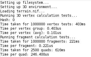
Is the Teensy fast enough?
This is the first big question. With speeds approaching old phone processors, which ran Minecraft Pocket Edition, it feels like there's a chance; but I imagine those phones had hardware to accelerate graphics. We don't have that. So, I've translated some of my Java LWJGL code into something arduino compatible, and ran some speed tests:Note: 720Mhz overclock for these testsAs you can see, we can draw a quad in less than 0.25ms. This includes a basic fragment shader, which handles basic transparency and blending, as well as an 8-bit depth buffer. These numbers should be realistic enough, as almost every part of the render pipeline is accounted for - the only important omitted part is sending pixel data to the GPU. That is a big concern though, as it could eat up a lot of CPU time that could be used for rendering. Another thing to note, is that each quad drawn in the quad test is 30x30 pixels, which is really quite large.
Considering the above numbers, we can draw about 65 30x30 pixel quads every frame, if we want to hit 60hz. That's not much, but it's certainly something to work with. Each block is drawn with 3 quads, but at least one quad is almost always very small, so we can call it 2 quads - this gives us about 32 blocks we can render each frame at 60hz. I'm sure there's some optimizations or hacks I can do to improve this - it's a work in progress. Nonetheless, this is certainly enough to run a (small) 3D game, no?
Other math: I want a display with about 192000 pixels. If about 2/3 of the screen is to be rendered on average, then this gives us 128k pixels to render every frame. Each pixel is rendered as one or more fragments, so we have a minimum of 128k fragments to render. Each fragment takes about 0.3us to render when including quad processing, so the minimum render time should be approximately 38.4ms, or 26 FPS. That's actually not that bad, all things considered; I expected it to be much lower. I mean, I wouldn't notice that FPS; I used to play Minecraft at 14 FPS when I was a kid :)
Display Limitations, Color, and Loading Minecraft's old terrain.png File
To make things extra fun, I'm going to run this with a uPD7220 GDC to handle the video output. Due to limitations of graphics memory size and bandwidth, we only get 16 colors. We can't use 24 bit color anyway, as the Teensy 4.1 would run out of memory. Also, for textures and the framebuffer, the Teensy 4.1 has to track transparency along with the color. Thus:
The Teensy uses an 8-bit format for textures and framebuffers - 4 bits of alpha and 1 bit for each color channel, including a brightness channel.
To load terrain.png, it must be converted to that 8-bit color format first
I'm using the odd 8-bit format above because it's simpler to implement, and because having more colors is of no advantage since I cannot display more than 4 bits of color anyway.
Another issue is loading the Minecraft terrain.png. Typically we load BMP files to get images into the Arduino environment, but these are uncompressed and don't have an alpha channel. PNG seems complex to load, and I didn't want to deal with it. For these reasons I created a simple image encoding and compression scheme which is easy for an Arduino to load, and I'll attach a Python script that converts the terrain.png to the .nif format for you. I don't think it's legal for me to distribute the terrain.png or a derivative like the terrain.nif image data, but it is easy to find online for you to convert. Or you can load whatever 256x256 image suits you. Anyway, the code loads the terrain.nif into a 256x256 byte image buffer in the 8-bit format described above. Some of the textures look good, some don't, but almost all are recognizable in the 16-color format:terrain.png, in 16 colorsI think that, ideally, a new terrain.png file would be made specifically to work with 4-bit color.
Without a Display
I don't actually *have* any of the Teensy hardware I want to run this on yet, so I'm actually running all the tests only through the Arduino serial monitor:Since each hex character is 4 bits, it is perfect for outputting our 4-bit color data. The above image is the top-left corner of the first image in this log - but represented in hex. To see the output from the render code, I have to copy and paste the serial output into a Python script which displays the image using matplotlib. This will work until I get my graphics hardware setup with drivers written; I only need to see one frame at a time for now. I can measure the FPS without seeing the output too.
Well, I hope you found this at least interesting, and stay turned for further developments. I'll be working on getting an actual render pipeline working, with a camera and scene. At some point we'll get very basic worldgen too.
 Dylan Brophy
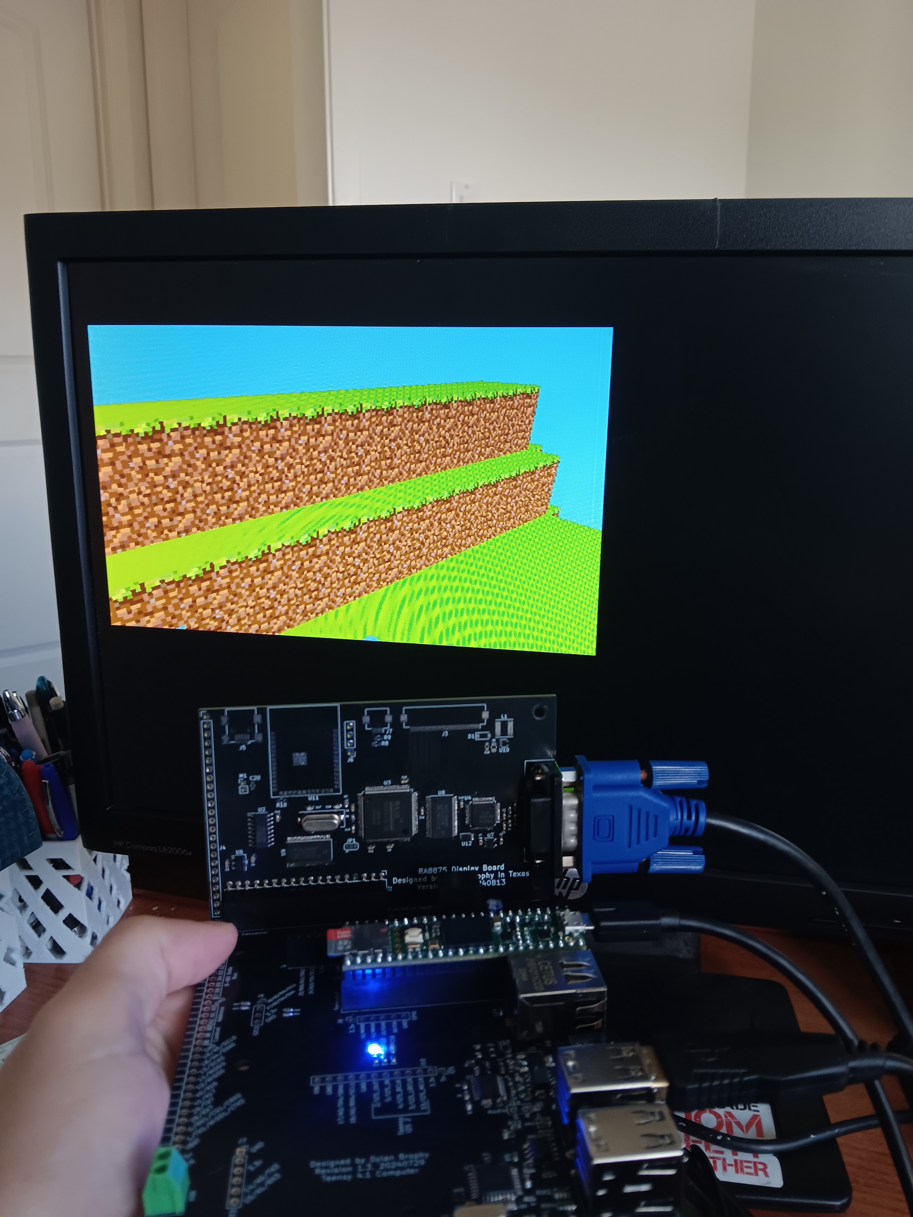
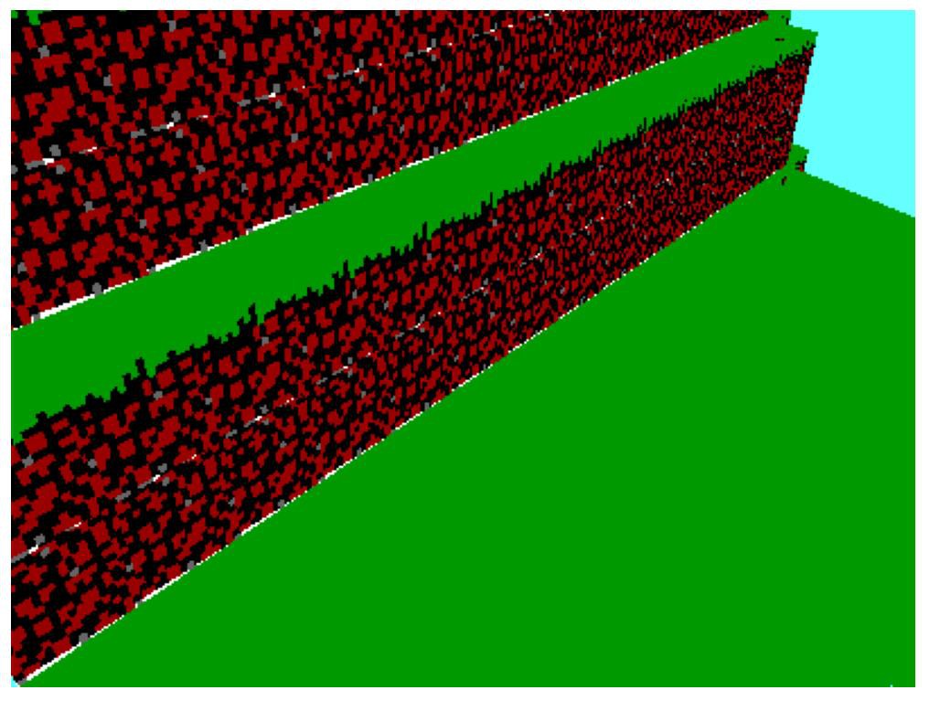 This is much better. The quads in this image are diamond shaped and rotated, but the textures are almost perfect! The shape of the terrain isn't too hard to make out, and with a more interesting scene, it could probably look a lot cooler. We do see nearby textures bleeding into the dirt texture though. To fix this, we can add a simple if block to prevent the texture coordinates from going out of bounds. Certainly, this can't affect our render time much. Certainly... right?
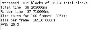 This is much better, especially for the higher resolution of 300x400.
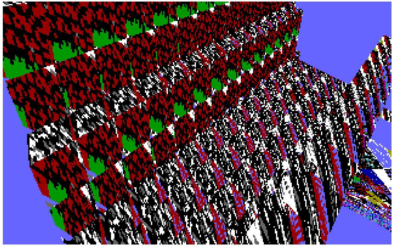 I can render some of the terrain's shape, but the texture coordinates are not handled properly, and I can currently only render one chunk. This is the first part for getting the rendering to do what I want, after this I need to:
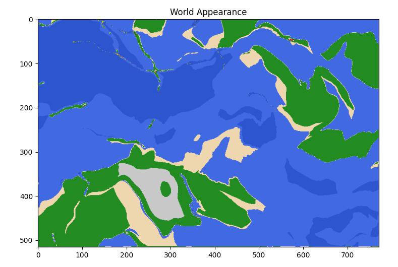 I have the rendering pipeline mostly working, but I need something to actually render. At some point world gen will be required, so I thought I should just implement it now.
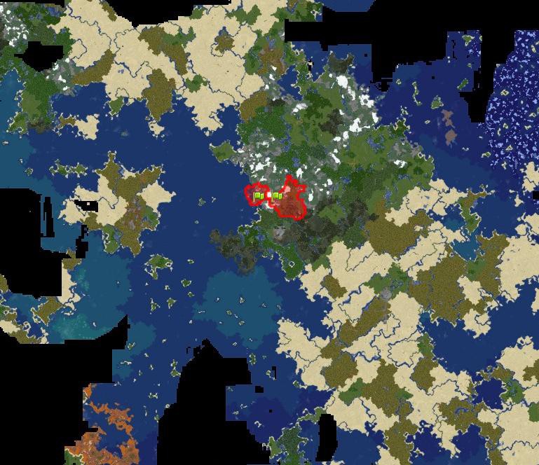 In real life, there are island chains, separated continents, deep trenches under the oceans, mountain chains, etc. All of these features are created by plate tectonics. But how can be simulate plate tectonics in a procedural generation algorithm?
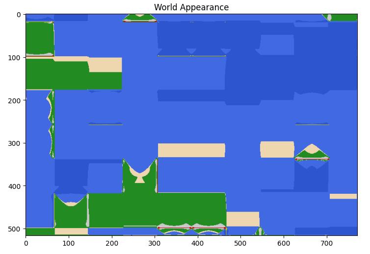 As you can see, it is very blocky. All I did to get from this to the world you saw in the first image, was apply changes to the x and y coordinates. This makes the blocky grid disappear, and allows us to bypass that tectonic plate issue.
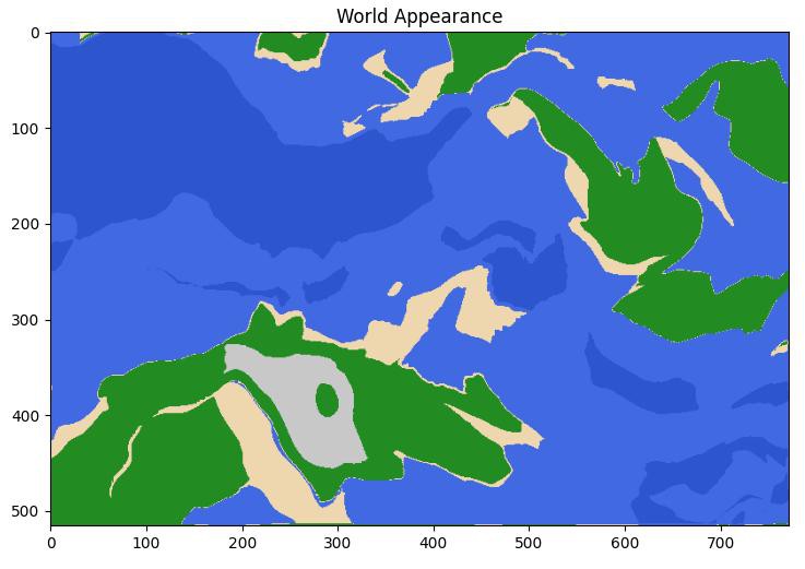 The terrain still looks good, but there are no island chains, deep trenches, or fault-related mountain chains.
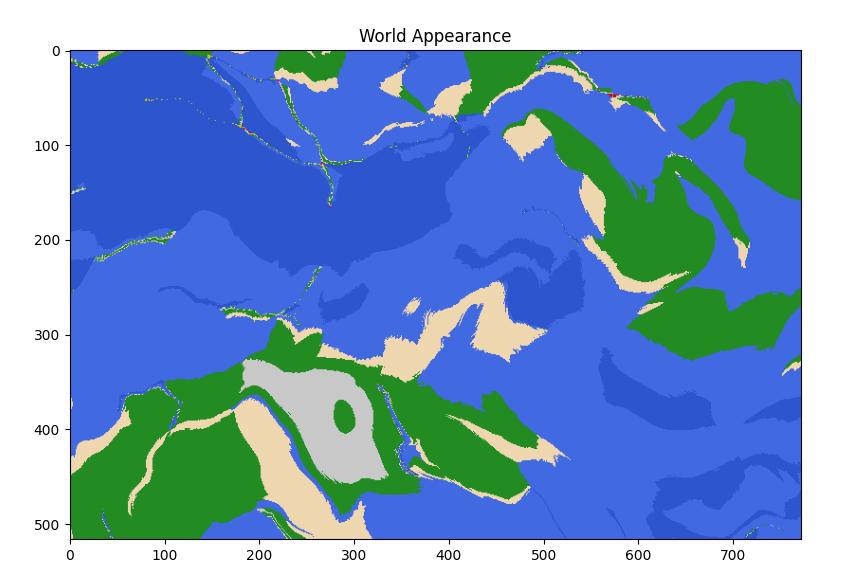 The smoothing may be too strong. I don't know. But it certainly needs some smoothing.
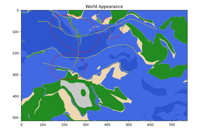 The orange lines show the top-to-bottom dividing lines on the grid. The yellow lines show side-to-side. Red circles regions that look unnatural due to the grid showing through. Now that I point out the grid, can you see the pattern in the volcanic activity, coastlines, and islands? Suddenly it looks a lot more organized. Ideally, this would be completely indiscernible, and for most of the map, it is.
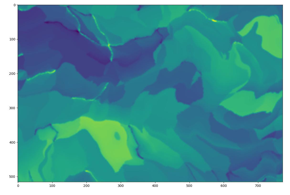 Some of the trenches in the north are very deep, and some of the faultline islands have tall mountains. Very fun.
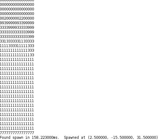 You can see that the world has generated, although my ability to look at it is quite limited at the moment. Each chunk generates in about 16 to 17 milliseconds. Since it is not guaranteed that any particular chunk will have land, or be without volcanoes, I had to make a function to generate a few chunks until it finds one with a suitable spawnpoint.
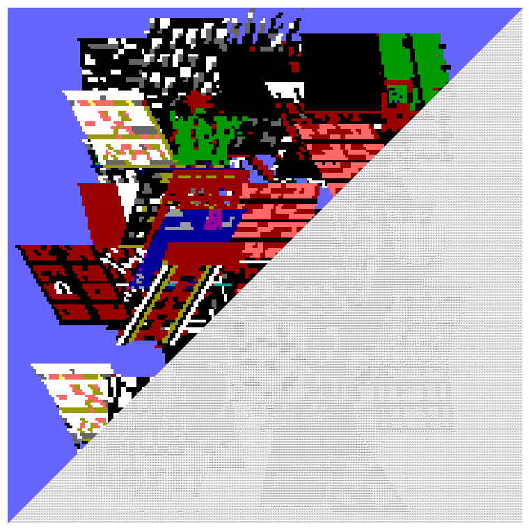

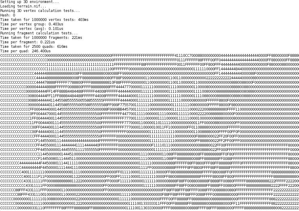 Since each hex character is 4 bits, it is perfect for outputting our 4-bit color data. The above image is the top-left corner of the first image in this log - but represented in hex. To see the output from the render code, I have to copy and paste the serial output into a Python script which displays the image using matplotlib. This will work until I get my graphics hardware setup with drivers written; I only need to see one frame at a time for now. I can measure the FPS without seeing the output too.