 Dean Netherton
Project Objectives
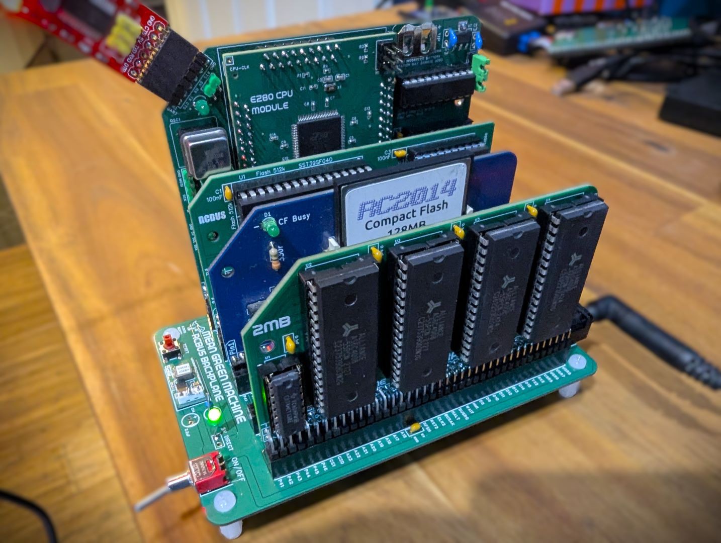
- Interface an eZ80 CPU to drive the various TTL 5V modules for the RC2014™ and other similar backplanes.
- Operate in a Dual-CPU mode - so that the original Z80 CPU and eZ80 can alternate access to the address/control and data buses.
- Figure out how to get software working easy in the system. Look at RomWBW and my Yellow MSX series. cross compiler tools etc.
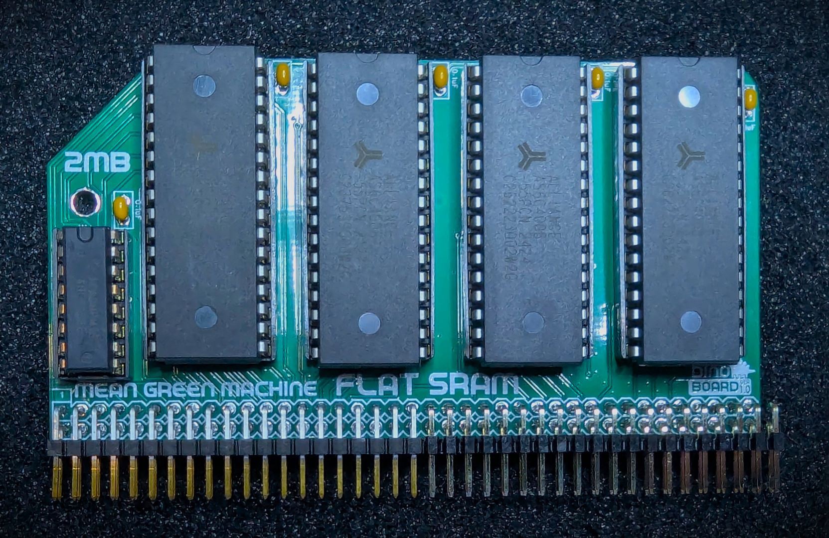
- Utilise some extra pins on the 80 pin backplanes to support a direct 24 bit address range for a possible 'Large Linear Memory Module'.
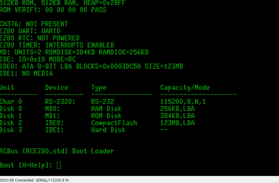
- Make it work with RomWBW and my Yellow MSX configurations.
- Learn SMD and how to hand solder surface mounted components.
Design Details
I have journaled some of my thinking around the design and learnings in the project log. If this is the your first viewing of the project, you may want to read through these journal entries sorted by 'Oldest' first. Click here: Journal Log
Which eZ80?
The eZ80 was originally released around the turn of the century. There are a number of variants available today. They all comes with additional features within the chip, such as Flash ROM, RAM, GPIO, UART, I2C and timers. Some can run at up to 20Mhz and other up to 50Mhz.
The key feature of the CPU above the original Z80, is its ability to address a full 16MB of memory. It has 24 address lines (8 more then the 16 for the Z80). Its has features built in to help run existing Z80 software in 'compatible' mode on this chip.
I choose the eZ80F92 variant for my designed. It can operate at up to 20Mhz, has 128K of on-chip Flash ROM and 8K of RAM. And lots of other features: UARTS, GPIO, timers, SPI and i2c. I may not be able to use all these features in my design though.
Surface Mount Device challenge
I have never worked with SMD stuff before. The eZ80F92 comes in a 100 pin LQFP package. Its pins are very tiny - and with my aging eyes, might be a challenge for me to hand assemble. Of course, the PCB fabricator can assemble these things relativity cheaply - that may be an option.
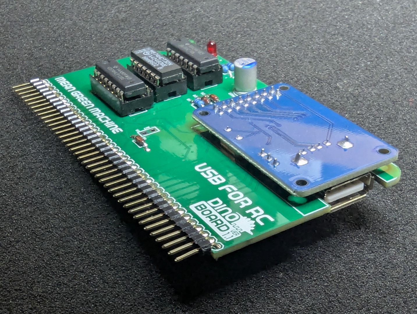
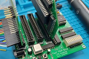
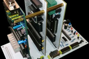
But I don't want to make an all SMD module. So I intend to place the eZ80F92 on an adapter board, with pins, that can be inserted into a conventional module PCB.
Inspiration
Of course, this is not the first hobby, DIY, retro solution using the eZ80 CPU. There are a few out there that inspired me.
- Agon - a cool little single board retro machine, with large following and lots of open source material available.
- eZ-Tiny - it might be small, but it is still very capable.
- The Z20X computer - this seems to be abandon now and the original website is gone - but it gave me the inspiration for a CPU breakout module.
- RC2014- where it all began for me.
- And my own Yellow MSX project.
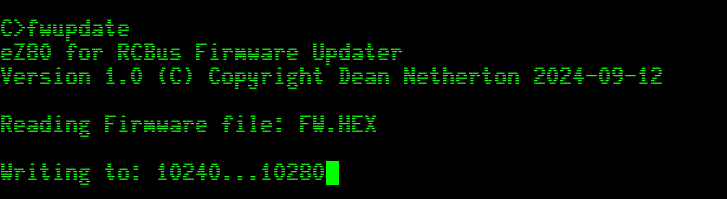
Below is a 10 second demo of the first operating prototype, driving the RC2014 Digital IO module. It just flashes the LEDS, so nothing very impressive - just confirms that the eZ80 is able to do I/O operations to another module. Lots of updates and software required to enable full operation. Eg: running CP/M, Basic, and eventually getting it to work in my Yellow MSX configuration.


 padnest
 Justin Skists
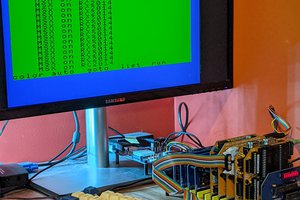
Hi Dean,
thanks for your answer. I've looked closely at everything on https://github.com/dinoboards/ez80-for-rc/, but I just don't understand the boot sequence.
Is the HBIOS ROM plugged into the 512K RAM/ROM module and can then be accessed at address 0x03xxxx?
I noticed that the schematics were not in sync with the software.
e.g. ez80-cpu-1.7.pld shows that EZ_X0 and EZ_X1 are no longer needed.
However, these signals can still be found in the schematics.
Likewise, EZ_XRD and EZ_RD are no longer needed as EZ_RD is probably mapped directly to the Bus.
You write in your answer that CS3 is mapped directly to MREQ, but in the schematics CS3 is mapped to EZ16_MREQ and EZ_MREQ from the eZ80 is mapped to 24MREQ via U6 and then placed on the Bus on User signal D8. It's difficult for me to understand and it confuses me.
I find the project really interesting. I've already written that I would like to recreate it.
I think it's good that you want to offer it on Tindie, but some Tindie sets cannot be delivered to Germany, but that's where I live.
I will have to be patient and wait for your update.
Cheers
Hajo