-
Belated Progress Report
01/22/2025 at 00:03 • 0 commentsOk, so its been quite a while since I provided an update for the *eZ80 For RC* module. What can I say, I am easily distracted.
Despite this lack of communicating, I have nonetheless, still found some time to make progress on various ventures related to the *ez80 For RC* module. There are quite a few things I am working on,
because, I get easily distracted. I keep starting a little project, but then I think - oh - what about this 'other' thing. (So unlike me!)I will try and summarise all that I have been working on over the last few months:
SRAM Memory Module
As per my last entry, I developed the Memory Module to give the system access to 2MB of linear addressable memory. Nothing changed here, other than the development of software to run on this memory.
CLang Compiler & runtime
To build applications for the system that can run in ADL mode on the memory module, I need a way to write such code easily and quickly.
The Options for writing code for the eZ80 (ADL):
1. Write in assembler. If I write my code in assembler, I can target ADL mode, using the 24 bit logic of the CPU. But its certainly a time consuming and error prone process. Fine for time critical code sections and low level logic, but for general application development - its rather slow.
2. Write C code with Zilog's ZDS IDE. Zilog's official C compiler can target the eZ80's ADL mode, allowing for full 24bit addressing and logic. But the C compiler is an older version of C (C99), so has some nice features missing. But more impactful, is the fact that its very much a Windows Application, tuned to the idea of firmware development, not general application development.
3. Z88DK. The Z88DK system is an amazing cross-platform Z80 solution. It can target the eZ80 CPU, unfortunately though, only for the standard Z80 mode. So its a no-go for me as it can't produce eZ80 ADL code.
4. CLang Port. The CLang port, developed for the TI-84 Plus CE/TI-83 calculator, and then later ported for the Agon, does indeed provide a modern C language compiler that can target the full ADL mode feature of the eZ80. But....
There were some challenges with the CLang tool chain for use within the RCBus/RC2014 ecosystems. The runtime for the *CE* calculator and the updated runtime for the *Agon* are developed for their respective Operating Systems. The question arose, how to make it work on my CP/M based RCBus/RC2014 system?
I have done a fair bit to convert/port the Clang compiler to my platform - probably too much to cover in this posting - I will try and post a separate entry detailing all the work.
Suffice it to say, I now have a cross-compiler that I can run on my PC and build CP/M 'executables' that can be copied to my kit and run - taking full advantage of the eZ80 processor.
The repo for the tool chain is at: https://github.com/dinoboards/ez80-clang
And within my main repo, I have a number of sample applications, that are compiled as ADL mode applications: https://github.com/dinoboards/ez80-for-rc/tree/main/apps
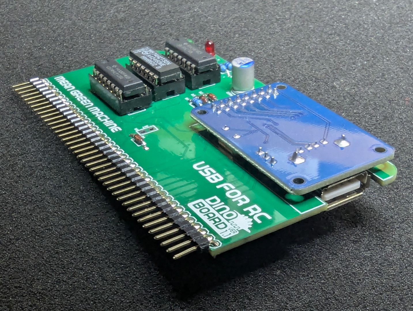
CH376 True USB Module
When I developed the Yellow MSX Cassette+USB module for my MSX series, I also wrote the code required to fully access the USB protocol. It is able to enumerate devices over USB Hubs, Mass Storage devices, USB Floppy drives, Printers, Keyboards, etc. All the code written for this USB logic, was developed using the Z88DK and SDCC C compiler.
I have wanted for a while now, to port this code into RomWBW to enable true USB support within the RCBus/RC2014 platform.
And I have done that. The code is not yet official yet... But its ready for merging into Wayne Warthen RomWBW's repo. I will submit it to Wayne, once he completes his current release's beta phase. In the meantime, the code is available on my fork of RomWBW.
My patch of RomWBW with full USB support is available at: https://github.com/dinoboards/RomWBW/tree/dean-ch376-usb-native-5
![]()
I will have this as a kit on my Tindie store shortly.
BBCBasic port
So now that I have a way to assemble/compile application code for the system, I decided to have a go at porting the BBCBasic language.
BBCBasic started out on the Acorn BBC Computers. A version for CP/M on the Z80 was written by R. T. Russell. This was later ported for the Agon. The Agon port included both changing the code to support its OS (MOS) and its graphics system. Dean Belfield then continued this porting to enable BBCBasic to run in full ADL mode.
I took Dean's code and then effectively undid the MOS and graphic porting - converting it back to CP/M - but kept its ADL target. So I now can type at my CP/M console:
```
EXE BBCBASIC
```I can run the BBCBasic interpreter, with access to 2MB of RAM, running on CP/M. At this stage I still have some code to write to enable it to access the various graphic capabilities of the V9958/TMS9918 video modules commonly available for the RCBus/RC2014 systems.
Code for my port can be found at: https://github.com/dinoboards/ez80-for-rc-bbc-basic/tree/dean-converting-to-ez80-for-rc]
Wolfenstein 3D port
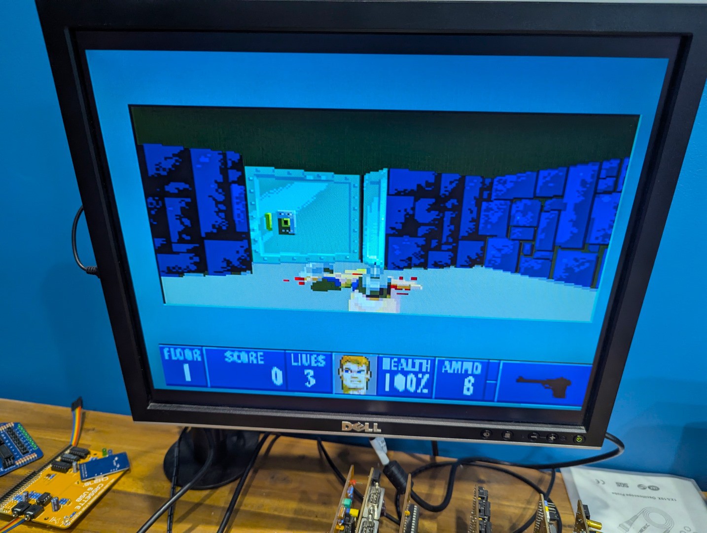
This was another distraction. I wanted to see if I could get Wolfenstein 3D running on the eZ80. I now had a C compiler, and a c-runtime that included some graphic support. So is it possible to run Wolf3d on my retro kit computer?
The original Wolfenstein for the x86 was developed for VGA graphics and the x86 segmented memory module (lots of far pointers, EMS, XMS memory). There is a bit of x86 assembly for some of the critical routines. It ran on 286/286 with frequency around 8 to 16Mhz. Could the eZ80 running at 25 or even overclocked upto 40Mhz compete?
The 286/386 CPUs has some key advantages over the eZ80 - perhaps the primary one being is that they are not 8 bit processors!. I am not sure of the full extent of the differences between the processors, but I suspect the eZ80 is missing quite a few features that might be critical for the performance needed to run Wolfenstien.
At first I had to convert some of the graphic operations that were tuned to a resolution of 320x200 to my V9958 VDP module's 256x212.
I have tried to take advantage of the eZ80's 24 bit registers/operations, and begun to convert some of the critical functions to assembly.
I have no idea if I can make this a truly 'playable' version - But when I first started, with no optimisation, I was able to get the demos playing at about 1 FPS. After some optimisation, got it upto 4FPS. And I know there is still a lot of optimisation potential. Perhaps I can do it, if I don't get distracted again!
The code for this port can be found at: https://github.com/dinoboards/ez80-for-rc/tree/dean/wolf3d/apps/wolf3d
> I had not based my port on the very original Wolf3D code. Instead I used the 'NakedWolf3D' port. The original C code has a lot of segmented memory access (lots of near and far pointers) and some x86 assembly. The NakedWolf3D is all C code - but targeting SDL for sound, control and graphics. But its an easier place to start for the porting.
![]()
HDMI V9958 Compatible FPGA Module
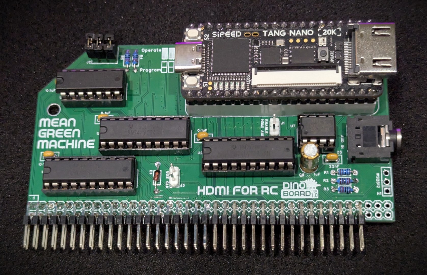
A module I had developed quite a while ago, then kind of abandon, was to the use the Tang Nano FPGA module to fully emulate the V9958 VDP module. This kit is now, I think, done. There may be some minor compatibility issues with the emulation of the VDP, but for the most part, all code targeted for the V9958/V9938 and TMS9918 just work.
A couple of key advantages of this module over the original is:
* Its output is HDMI - so much easier to connect to modern displays - with a nice crisp image.
* It a lot faster than the original chip - so my Wolf3d conversion is a little more ... possible.![]()
Z80 all the way down
With the HDMI V9958 Module mentioned above, it raises that 'discussion' about retro. Is it retro if its not original hardware? Is emulation as good as the original? I can run pretty much any Z80 based system in my modern PC's web browser. Javascript can emulate Z80 code faster than original hardware could ever hope to achieve. This is an indication of how things have changed.
Rather than 'porting' code, to solve the 'compatibility' issues with running original Z80 code, could the eZ80 emulate a Z80?. Can I get the eZ80 to work on my Yellow MSX system, running MSX code? The emulator would need to map the I/O appropriately (as per the porting work done for RomWBW). Would it be fast enough? Can an overclocked eZ80 running at around 30Mhz emulate sufficiently a standard Z80 running at 4Mhz?
This is just an idea for the moment.
DRAM Memory Module
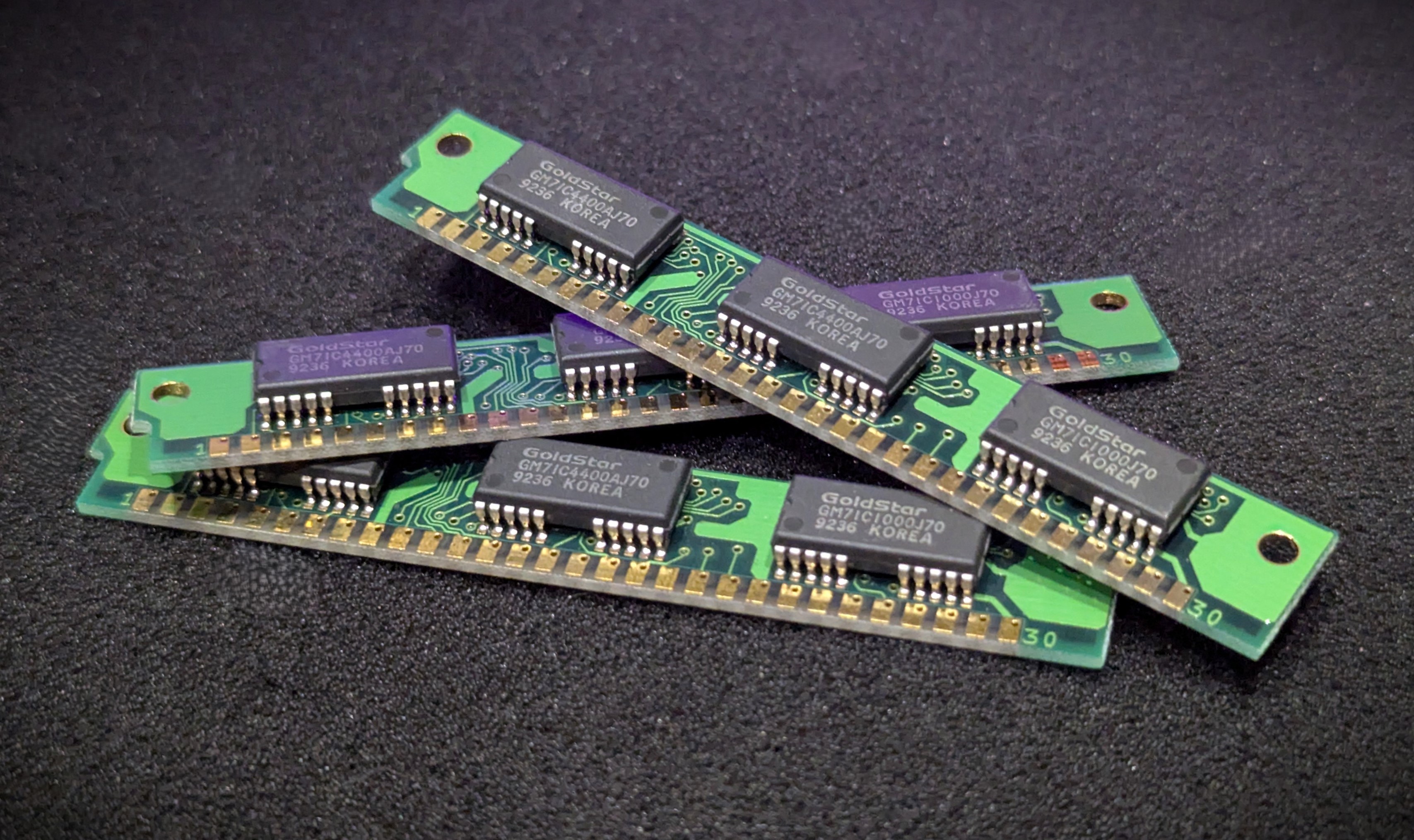
Another idea, that I have also done some exploration with, is to try and develop a 32 pin DIMM DRAM interface module for the ez80. Can I provide the eZ80 with access to a full 16Mb of dynamic RAM DIMM? This would be cool if I can figure it out - and find the time - and not get distracted again.
![]()
-
2MB Flat SRAM Linear Memory Module
12/10/2024 at 23:24 • 0 commentsIn a typical Z80 RC2014/RCBus configuration, the Z80 processor, which is limited to a 16 bit address bus, can only directly access 64k. The RC2014 Modules such as the 512K RAM/ROM modules use bank switching to allow the Z80 to access more memory.
Although this works, it is a bit restrictive. If you attempt to write a program that is larger than 64k, or needs to access more memory, its got to figure out how to access the various banks, and switch them in and out as required. It can get complicated.
The eZ80 has a 24bit address bus, and when running in ADL mode, can directly address up to 16Mb of memory, enabling the ability to write larger programs much easier.
So for the eZ80 to shine, we need a new memory module that works with the 24bit address and not use any bank switching.
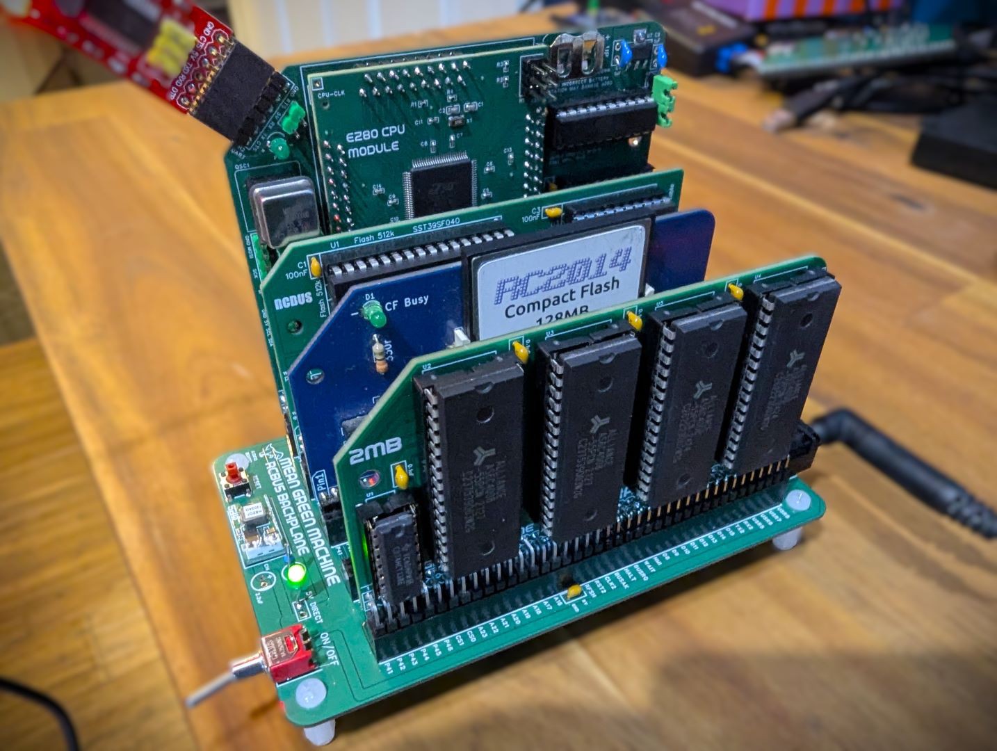
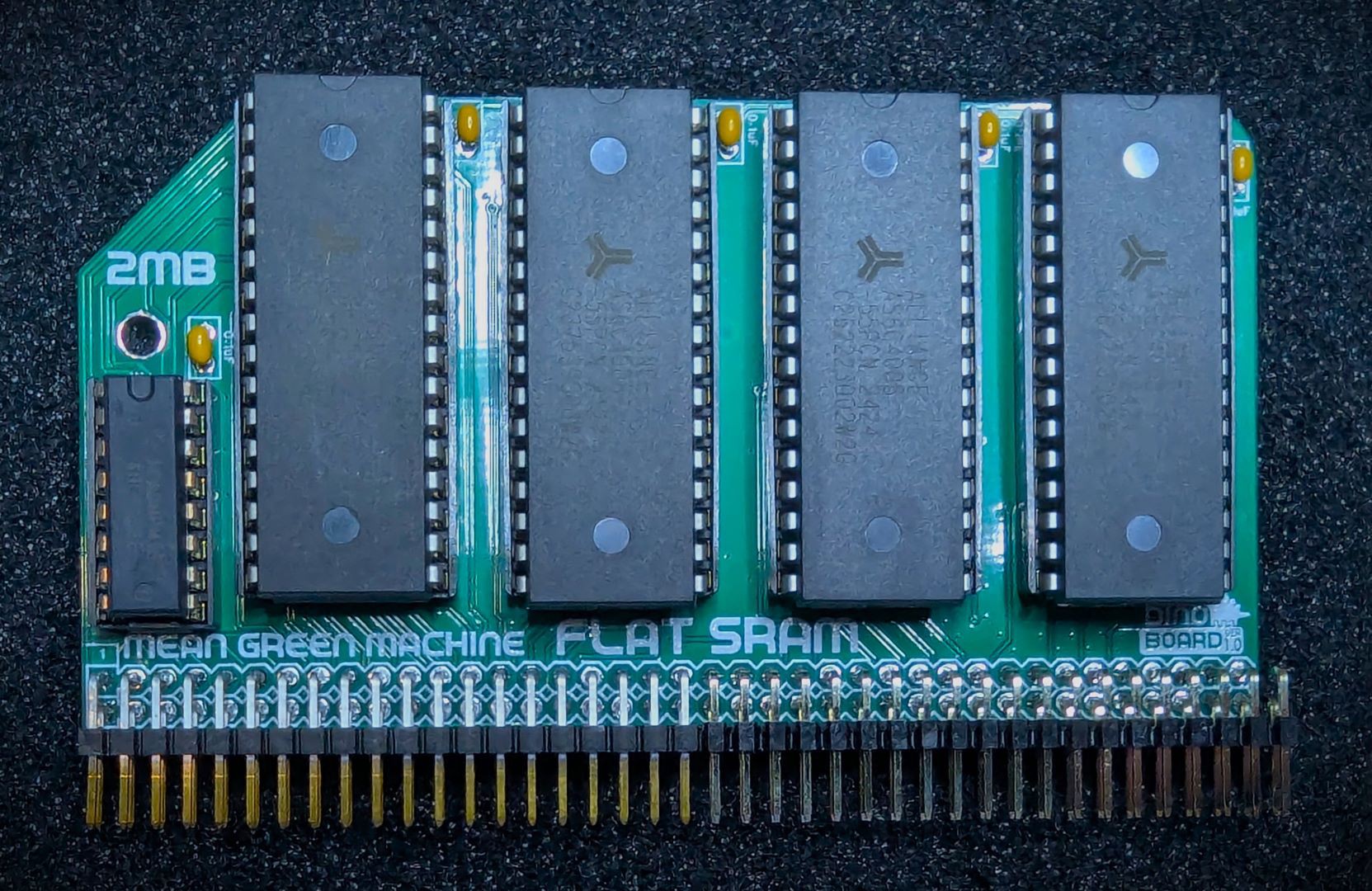
Therefore, I developed a new Module for the eZ80 for RC CPU system. The **2MB Flat SRAM module**. It allows the eZ80 to see up to 2MB of linear RAM. The module has sockets for up to 4 AS6C4008 (512k) SRAM chips.
![]()
![]()
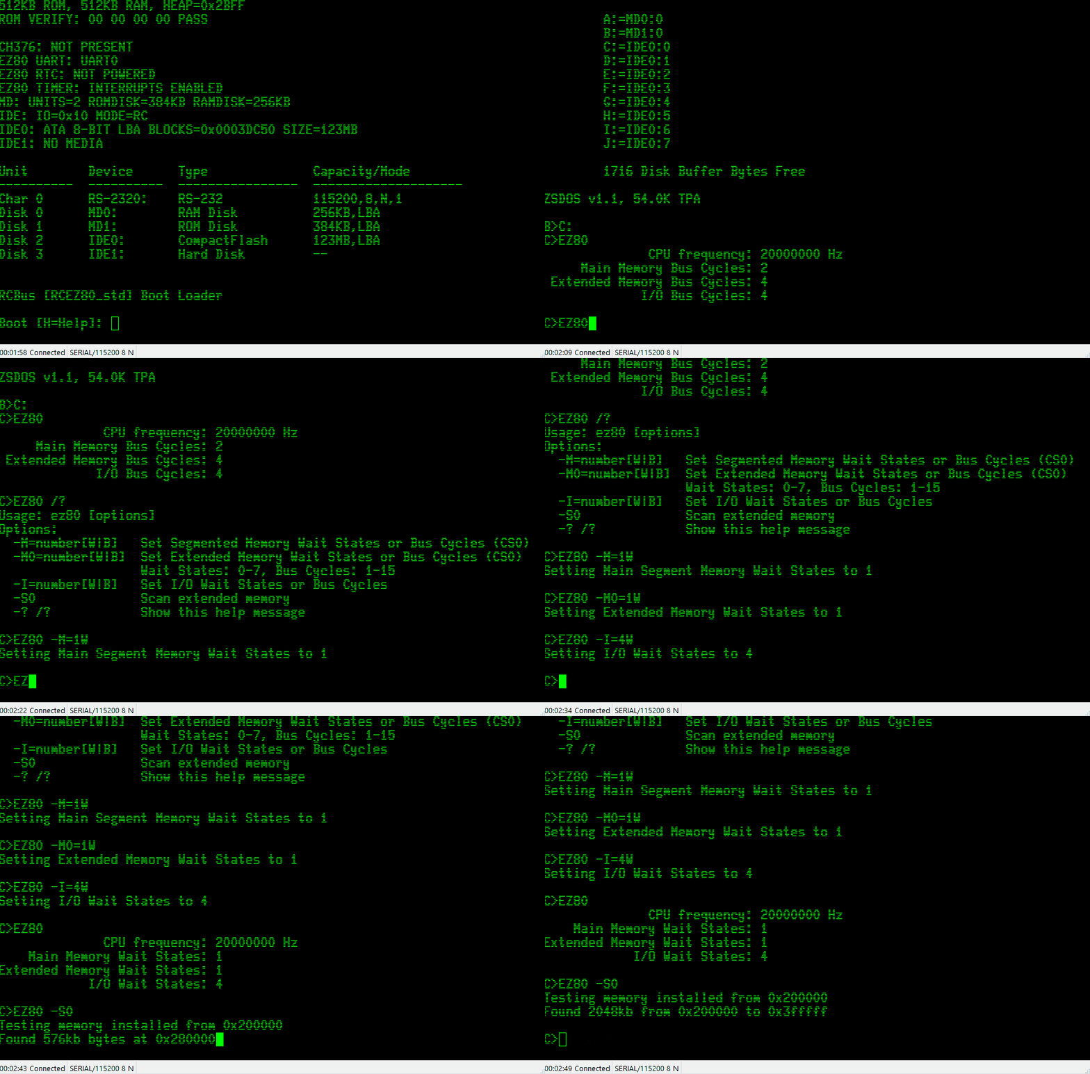
I wrote a little CP/M utility (EZ80.COM) to help with managing and testing the memory and (I/O) systems.
![]()
The firmware has been updated to enable the extended linear memory:
              +-------------+
   0x00 0000  |             | On Chip 128k flash ROM
              |             | (boot up firmware)
              |             |
              +-------------+
   0x02 0000  |  ~ ..... ~  | Unused
              +-------------+
   0x02 E000  |             | On Chip 8K Fast RAM
              +-------------+
   0x03 0000  |             | External Banked Switch
              |             | 64K ROM/RAM
              +-------------+
   0x04 0000  |             |
              |  ~ ..... ~  | Unused
              |             |
              +-------------+
   0x20 0000  |             |
              |             | External 2MB Linear
              |             | SRAM
              |             |
              +-------------+
   0x40 0000  |             |
              |  ~ ..... ~  | Unused
              |             |
              +-------------+
   0xFF FFFF
Now all I need is a figure out a way to write applications that can run from within this linear address space and take full advantage of the eZ80!
-
Kit available on Tindie
10/06/2024 at 10:04 • 0 commentsThe eZ80 for RC kit is now available from my Tindie store.
A super easy kit to build with everything needed to explore the most advanced Z80 based CPU available.
Click here to purchase your own eZ80 for RC kit.
I have also started to build up a new website detailing all my kits: www.dinoboards.com.au
It includes a page for the new eZ80 for RC kit: www.dinoboards.com.au/ez80-for-rc
The plan is to consolidate all supporting materials for all kits and projects on this new site.
-
Pi Pico Programmer
09/29/2024 at 08:38 • 0 commentsThis weekend, I made significant progress in making a PI Pico module connect to the eZ80. Enabling the ability to erase and write to the on-chip flash ROM. This will be an alternative and cheaper way to program the eZ80 compared to Zilog’s Smart Programmer.
The Pi Pico Programmer connects to the eZ80’s ZDI interface, a 2 pin (similar to i2c) serial interface. The Programmer can transmit commands to halt, inspect, debug, erase and write to the on-chip 128K Flash ROM.
Getting it operational was quite challenging. My first challenge, that took way longer than I had expected, was to install the compiler/build tool chain for the Pico. Once that was done, I had the ability to write C code for the Pico that can drive some GPIO pins. So it was just a matter of discovering the ZDI signalling protocol to command the eZ80 to erase and write to its flash (and do a few other operational things)
This proprietary interface is a bit like I2C, but not quite… Its documented by Zilog in the eZ80 manual. I did find though, that the documentation is sometimes a little brief or confusing.
The development process mostly entailed me flashing some code on the Pi Pico - verifying that the GPIOs are toggling as expected - then connecting it for real to my eZ80 and see if that’s actually what Zilog wants! A lot of head scratching and trying over and over.
The Pi Pico Programmer is now able to to program/flash the eZ80 - it still needs some polish - but is sufficient for now.
I intend to detail the solution, with appropriate pictures in the main repo. I have also designed a small PCB to mount the Pi Pico and a 6 pin header. Should make for a very neat solution.
I am not the first to use a cheap modern Microcontroller to program an eZ80. There are some projects for the Agon using its onboard ESP32
-
RomWBW Integration
09/22/2024 at 09:24 • 0 commentsI am very excited to announce that Wayne Warthen has accepted my pull requests for the eZ80 module into his mega RomWBW project. The eZ80 support is now part of the mainline code base. Still very much under development and early alpha - but official!
![]()
I am very thankful to Wayne for his assistance in the development of the eZ80 for RC2014/RCBus.
Wayne has also received a kit and will soon be able to personally validate the eZ80 operation.
And in other news, I started experimenting with a Pi Pico this weekend to see if I could make a programmer for the eZ80 (as a possible replacement for the very expensive Zilog programmer). I thought to myself, surely this cant be too hard to do. When will I learn not to call myself Shirley!
![]()
-
Benchmarking
09/15/2024 at 10:36 • 0 commentsMy primary goal with the eZ80 module is to achieve maximum compatibility with RC2014/RCBus modules and configurations. The eZ80 is a significantly faster processor. However, to ensure communication with older, slower retro modules, appropriate wait states must be introduced, which means some performance will be sacrificed. Despite this, the system remains much faster than a standard Z80 running at 7MHz.
I ported some benchmarking software from the z88dk library, which includes the classic Dhrystone and Whetstone benchmarks to give me some insights on the degree of performance this system operates at, compared to a stock RC2014 build.
I ran these benchmarks on various configurations and at different CPU frequencies, and the results were quite interesting.
When the eZ80 boots up, it detects the current CPU frequency and adjusts the timing for accessing the external ROM/RAM module and its own on-chip flash ROM. I chose conservative settings and calculations. As a faster oscillator is installed, the boot-up firmware will increase the extra wait states required when accessing memory and I/O devices.
The purpose of this benchmarking was not to showcase raw speed. Other eZ80 systems can achieve higher speeds by using fast RAM chips, typically SMD RAM chips soldered next to the CPU. The fast RAM chips allow the eZ80 to run at its full potential. But I tend to think, if I wanted a faster solution, I could probably achieve orders of magnitude increases by running everything in JavaScript within my main PC’s browser.
The Results
Stock RC2014 System @ 7.372Mhz
First, I ran the two benchmarking utilities using a stock RC2014 system with a standard Z80 CPU running at 7.372MHz, an SIO/2 module for serial communication, and a V9958 VDP module to generate a 50Hz timer tick for time reference.
- Dhrystone score: 556.2
- Whetston score: 8
Stock RC2014 System @ 20Mhz*
I then conducted the same tests, using my Turbo CPU module - the fastest standard Z80 I have. This is a CPU module for the RC2014/RCBus systems, that can run a standard Z80 at 20Mhz. (If you are not familiar with this module, check it out over in my Tindie Store https://www.tindie.com/stores/dinotron/)
- Dhrystone score: 1144.2
- Whetston score: 16.5
* The Turbo CPU does not run its Z80 at a constant 20Mhz - it will, if any I/O operations are performed, briefly slowdown to a more typical speed (7.372Mhz). The interrupt timer tick from the V9958 will cause the CPU to do some I/O operations, thus down clocking the CPU for short bursts.
eZ80 System @ various clock frequencies
Below is the result of running the benchmark applications for the eZ80 at different CPU Frequencies. Note how the wait states increase as the clock goes up.
Cpu Frequency Memory
W/SI/O
W/SFlash
W/SDhrystone
ScoreWhetstone
Score7.37 1 6 0 1149.7 14.4 14.75 1 6 1 2301.1 28.9 16.00 2 6 1 1680.4 21.1 18.43 2 6 1 1938.9 24.3 20.00 2 6 1 2103.1 26.4 24.00 2 5 1 2520.3 31.7 * 25.00 2 5 1 2625.6 33.0 * 32.00 3 7 2 2536.1 31.8 35.00 4 7 2 2226.0 28.0 40.00 4 9 2 2544.0 32.0 Paradoxically, it does seem that sometimes, a faster CPU frequency, actually results in slower performance. For example, the 14.74MHz CPU outperforms the 18.43MHz CPU because the latter is heavily impacted by the need for an extra wait state.
I know that some configuration are perhaps overly conservative (eg: 32Mhz will run at 2 W/S just fine) - and with some more time to experiment, more ‘performance’ can be achieved.
Despite this, the current solution is still significantly faster than the stock RC2014. Additionally, the solution remains highly compatible, even when overclocking the eZ80.
And yes, I have successfully overclocked my eZ80 to 40MHz, even though Zilog rates it for a maximum speed of 20MHz. I am eager to test even higher frequencies, but I lack the necessary oscillators to generate higher clock rates.
Next, I need to start generating some Mandelbrot sets!
-
Hot Flashing
09/15/2024 at 09:36 • 0 commentsBeen working on understanding and writing code to re-flash the on-chip ROM from a CP/M application.
I have written an application that allows for the ‘updating’ of the on-chip ROM without the need for the Zilog Programmer.
Designed a system, where I can install dual firmwares. A default/fallback bootable firmware and an ‘alternative’ firmware.
The first firmware is flashed, using the Zilog programmer, within the first 64K page of the 128K on-chip ROM.
The CP/M application
FWUPDATE.COMcan then be executed within CP/M, to flash an ‘alternative’ firmware in the 2nd 64K page.On reboot, the system sees this new ‘alternative’ image and boots using that version. Should this new ‘alt’ firmware fail to launch HBIOS/CPM successfully, the main boot loader will switch back to the main ‘firmware’.
![]()
A future goal will be to develop, using something like a PI Pico, to create my own external programmer. A Pi Pico, or other similar cheap microcontroller, will be a lot cheaper than the Zilog Programmer
-
Factory assembled CPU Modules
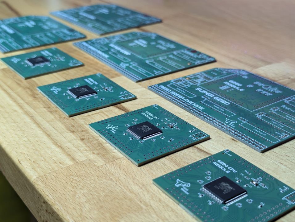
09/06/2024 at 23:17 • 0 commentsLast week, I submitted to the PCB manufacturer, an order for assembled CPU modules. This is the first time I have submitted an order to the factory to place and solder components onto one of my PCB designs. It was quick, easy and generally quite simple.
And now they have arrived.
![]()
Will they work?
Only one way to find out. Of course, I live on the edge, and ordered a version of the module (and associated interface PCB) with some last minute untested changes.
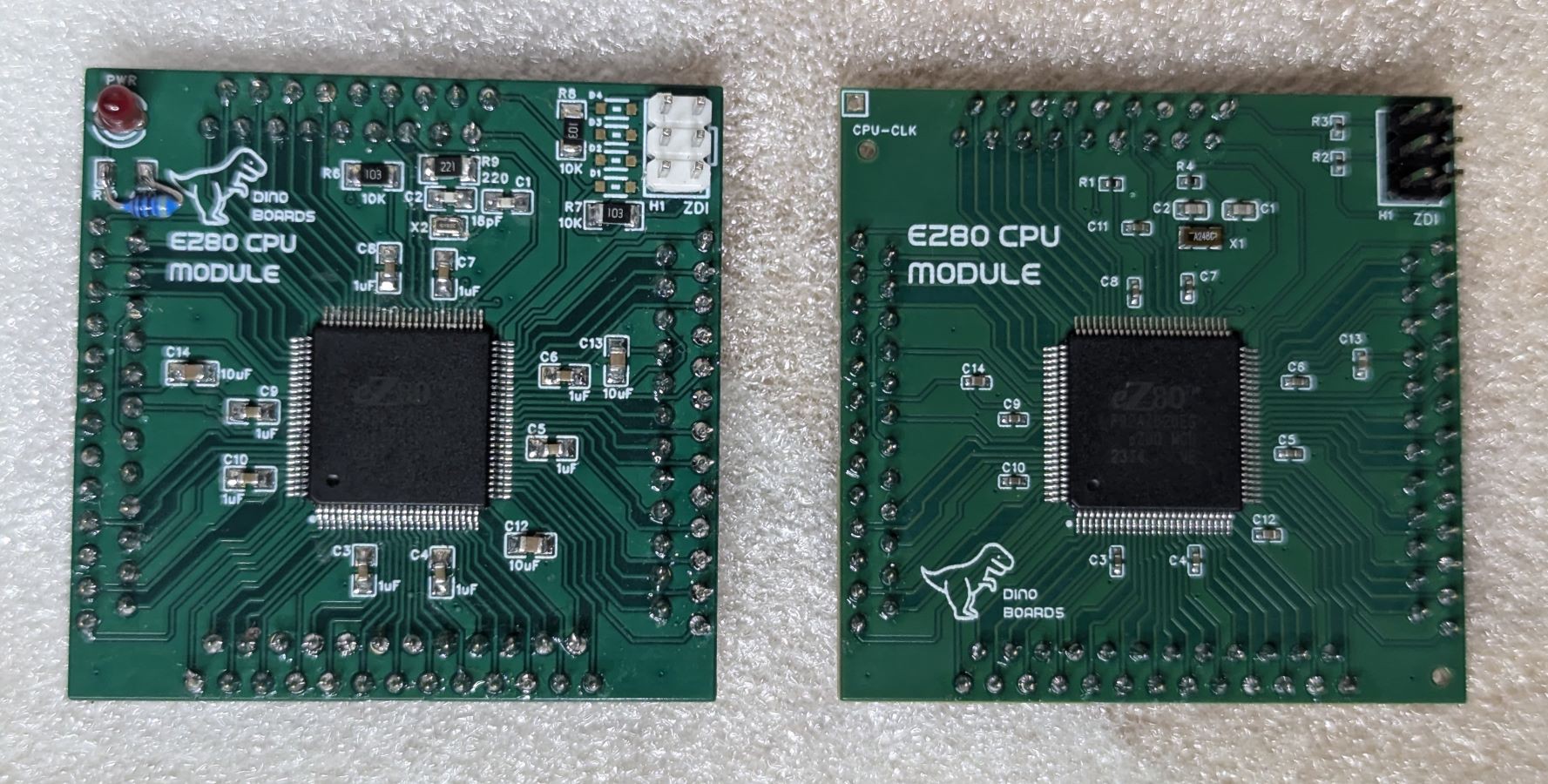
One change was the size of the various SMD capacitors and resistors. For the hand assembled units, I had selected as large a footprint I could - to reduce the challenge when hand soldering. But for the factory assembled units, it was cheaper and easy to use smaller components. Smaller sizes, I gather, are not only cheaper, the de-coupling capacitors would likely have a lower inductance -- meaning they will work just that bit better at absorbing all those high frequency digital spikes.
The other change was a slight 'correction' to the positioning of the interface pins. The inner rows are now 2.54mm (100mil) from the outer rows. (The original versions had a rows separation of 3mm)
The factory assembled units only assembled the surface mount components. I still needed to solder the programming header and the 93 PCB pins.
Me vs Factory
Here's a comparison of my hand-assembled module (left), and the factory assembled unit (right). Notice the much smaller components:
![]()
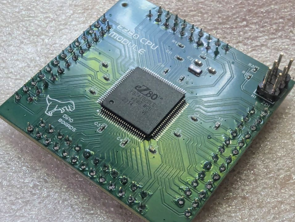
Close up of the factory assembled unit, after I have soldered in the header and PCB pins:
![]()
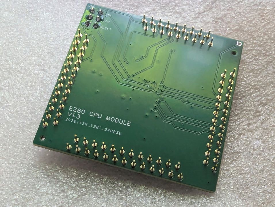
The back of the module is basically the same:
![]()
I am please to say, I have since installed the new CPU Module and Interface board into my RC2014 and it all works just like the hand assembled units.
-
RC2014/RCBus Mapping
09/06/2024 at 04:25 • 0 commentsAs the eZ80 CPU has some differences and additional control signals, I need to consider how some of these signals have to be mapped, and how their slight difference may impact compatibility. I have already had to 'resolve' issues with the timing of the WR signal to ensure operation of the Bank Memory module and the Compact Flash module.
Many people have installed various alternative CPUs into their RC2014/RCBus based systems, from the various Zilog processors (Z180, Z280) and Intel 8080 to CPUs with very different timings and signals, such at the 6502. The eZ80 is now, just another CPU for the platform.
On the electrical front, the eZ80 operates at 3.3V, but is 5V tolerant. The interface module I have built, uses a number of 74HC245 buffer chips to step-up all outgoing signals to 5V. The frequency of these signals are going to be higher and have a much quicker rise and fall times compared to a stock Z80 system. In all my testing to date, I have the eZ80 configured to operate in Z80 Bus Mode. So in theory, an eZ80 operating at 20Mhz will drive the Address and Data Buses at a similar rate as a Z80 operating at 20Mhz - although its not quite that simple. (Of course the eZ80 will still run at full speed when operating from its on-chip RAM/ROM, and combined with the chips ability to execute more instructions per clock cycle -- we will still have a very fast processor compared to a standard Z80)
Nonetheless, any CPU operating at 20Mhz will typically exceed the operating timings requirements for many RC2014/RCBus modules.
The eZ80 can be configured, as mentioned, to operate its Address, Data and Control Bus in various 'Modes' of operation. It can be configured to its default eZ80 Mode, or a 'compatible' Z80 Mode, or if you wish, an Intel or even the very different Motorola Mode.
In the default eZ80 Bus Mode the CPU's reads and writes can be conducted within a single clock cycle. Compared this to the Z80 mode, where the reads/writes are conducted over at least 3 clock cycles. Of course, the targeted memory, or I/O device, can send a WAIT signal back to the CPU, extending the time taken for any transfer. But this requires the memory to be able to trigger that WAIT signal before the CPU has moved onto the next cycle. A lot of retro modules use older chips that could not possibly operate at these data rates. Even the modern memory chips (AS6C4008 SRAM) typically used in the RC2014/RCBus systems will struggle at this rate.
Thankfully, the eZ80 can also be configured to include its own additional WAIT states. So with the appropriate configuration, we can drive our Memory and I/O devices at a rate that is kept within the required timing specifications.
The modes are configured through the use of the eZ80's Chip Select signals (CS0, CS1, CS2, CS3). Each of these CSx lines can be configured to only be activated for specific address ranges. For example, I have configured CS3 to use *Z80 Compatible Bus Mode* and only activate when a memory read or write happens in the address range of 0x030000 to 0x03FFFF. And configured CS2 to also use *Z80 Compatible Bus Mode* and activate when an I/O request happens in the address range of 0xFF00 to 0xFFFF.
The eZ80 to RC2014/RCBus mapping
Below is a brief description of some of the key signals on the RC2014/RCBus backplanes and the eZ80 equivalent and any differences.
A0-A15 and D0-D7
These signals are as expected; the address from the CPU and the bi-directional data bus.
19 M1
The eZ80 does not have an M1 signal - it has INSTRD (instruction read) signal. For simplicities sake, I have not mapped this line -- I just pulled it high with a 10K resistor.
21 - Bus Clock
My eZ80 CPU module has an onboard oscillator. I have tested oscillator's with frequencies from as low as 7.3728MHz up to the CPU's rated 20MHZ and overclocked to 32Mhz. But I don't send this clock signal over the bus. I use one of the on-chip counters to divide the CPU clock by 4 and optionally send that over the bus.
By supplying a more 'typical' clock rate on the bus, any modules that need a clock, for example the various retro sound modules, can be operated without the need for a separate clock module.
One issue with this though, is the V2 revision of the RC2014 Compact Flash module. It uses this Bus-Clock signal to adjust the timing of the WR signal.
Because this generated Bus-Clock is not phased with the timing of the WR signal, there may be issues, as it's been designed with the expectation that the bus clock is the CPU clock. I have yet to test V2 of this module, but I suspect it will only work if I configure the eZ80 to have lots of additional wait states.
22 INT
Technically the eZ80 (or specifically the eZ80F92), does not have a general purpose INT signal. Many of the GPIO's can be independently configured to trigger an interrupt request in the CPU.
I have tired the eZ80's GPIO pin PB4 to the INT line of the RC2014/RCBus.
23 MREQ
This signal is *not* the eZ80's MREQ signal. This signal is driven by the eZ80's CS3 signal.
The intent of this signal is to indicate a 16 bit only memory device access. (See CS0 and CS1 below for potential 24 bit memory access)
Although the upper address lines (A16-A23) will also be activated, any attached *original* 16 bit memory module will not have any connection to these new address lines, so of course, they are ignored.
CS3 is configured in the eZ80 boot code, (at time of writing), to only activate for memory addresses in the range of 0x030000 to 0x03FFFF. Its also configured to have an appropriate bus timing to avoid attempting to read/write as a rate faster than the typical memory modules can achieve.
The timing of this signal is a little different than the MREQ of the Z80 or eZ80. Is will be activated a little bit before the standard MREQ would. Testing so far indicates that this does not introduce any compatibility issues.
24 WR
This signal is not the eZ80 WR signal. As mentioned above and in previous posts, the timing of the eZ80's WR signal during I/O operation had to be modified to have a reduced period of activation, to enable a longer post activation hold time. This enables any device that expects a valid address (or data) still present to have time to acquire the address/data state.
For I/O requests, the WR line goes low when the eZ80's WR line goes low, but is pulled high a cycle or 2 before the eZ80's WR line goes high. For memory request, the WR signal has the same timing as the eZ80's WR signal.
26 IORQ
This signal is generated from the eZ80's IORQ signal, but with a slight difference in timing when conducting writes.
Due to the way the eZ80 has been configured, the IORQ is expected to only activate when the eZ80's CS2 signal is also activated. CS2 is configured to only trigger for any I/O operation within the address range of 0xFF00 to 0xFFFF.
To align with the 'shortened' WR signals, the IORQ will also go high as the bus version of the WR signal goes high.
This signal operates in a similar way to MREQ, in that its designed to work with original (8 bit addressed) RC2014 and compatible modules.
The CS2 timing and bus mode are configured within the eZ80 to ensure compatibility with typical retro I/O modules.
> The IORQ will activate if the CPU's attempts to access any address outside of the configured range of CS2. In this case, the busses will be operating in eZ80 mode and will be well outside of the timing requirements for many RC2014/RCBus modules.
35-36 TX/RX
Not connected. The interface module has UART signals (RX,RX,CTS,RTS). But I have not mapped these to the bus.
37-40 & 77-80 USER1-USER8
Not connected.
49-56 A16-A23
The higher address signals of the eZ80.
59 RFSH
Not connected. The eZ80 does not have such a signal.
63 HALT
Not connected. Perhaps in a later revision of the Interface Module, I may map this signal to the eZ80's HALT signal.
66 NMI
Not connected. Perhaps in a later iteration of the Interface Module, I may map this signal to the eZ80's NMI signal.
48 CS0, 49 CS1
Connected to the eZ80 chip select signals. Not buffered, as such they operate at 3.3V.
-
eZ80 i2c Interface
08/18/2024 at 06:02 • 0 commentsBeen learning about i2c over the last few days. Today I managed to get the eZ80's i2c interface to drive a little Adafruit 8x8 LED matrix i2c module.
eZ80 CPU for RC2014 and other backplanes
An eZ80 CPU Module that works within the RC2014 ecosystem and other similar backplanes
 Dean Netherton