Close
0%
0%

eZ80 CPU for RC2014 and other backplanes

An eZ80 CPU Module that works within the RC2014 ecosystem and other similar backplanes

Similar projects worth following
The goal of this project is to design and build a module for the RC2014™/RCBus and my Yelllow MSX Series, that can operate as a complete CPU module and drive the various available modules.

The eZ80 Zilog CPU is an updated version of Z80 CPU. It comes in a few variations with many on chip facilities in addition to the basic CPU, such as flash ROM, RAM, GPIO and other IO services. See the Wikipedia page for basic overview of the CPU (https://en.wikipedia.org/wiki/Zilog_eZ80)

(An alternative version of this site can be viewed at: https://dinoboards.github.io/ez80-for-rc2014-backplanes/)

Project Objectives

  • Interface an eZ80 CPU to drive the various TTL 5V modules for the RC2014 and other similar backplanes.
  • Operate in a Dual-CPU mode - so that the original Z80 CPU and eZ80 can alternate access to the address/control and data buses.
  • Figure out how to get software working easy in the system.  Look at RomWBW and my Yellow MSX series. cross compiler tools etc.
  • Utilise some extra pins on the 80 pin backplanes to support a direct 24 bit address range for a possible 'Large Linear Memory Module'.
  • Make it work with RomWBW and my Yellow MSX configurations.
  • Learn SMD and how to hand solder surface mounted components.

Design Details

I have journaled some of my thinking around the design and learnings in the project log.  If this is the your first viewing of the project, you may want to read through these journal entries sorted by 'Oldest' first. Click here: Journal Log

Which eZ80?

The eZ80 was originally released around the turn of the century.  There are a number of variants available today.  They all comes with additional features within the chip, such as Flash ROM, RAM, GPIO, UART, I2C and timers.  Some can run at up to 20Mhz and other up to 50Mhz.  

The key feature of the CPU above the original Z80, is its ability to address a full 16MB of memory.  It has 24 address lines (8 more then the 16 for the Z80).  Its has features built in to help run existing Z80 software in 'compatible' mode on this chip.  

I choose the eZ80F92 variant for my designed.  It can operate at up to 20Mhz, has 128K of on-chip Flash ROM and 8K of RAM.  And lots of other features: UARTS, GPIO, timers, SPI and i2c.  I may not be able to use all these features in my design though.

Surface Mount Device challenge

I have never worked with SMD stuff before.  The eZ80F92 comes in a 100 pin LQFP package.  Its pins are very tiny - and with my aging eyes, might be a challenge for me to hand assemble.  Of course, the PCB fabricator can assemble these things relativity cheaply - that may be an option.  

But I don't want to make an all SMD module.  So I intend to place the eZ80F92 on an adapter board, with pins, that can be inserted into a conventional module PCB.

Inspiration

Of course, this is not the first hobby, DIY, retro solution using the eZ80 CPU.  There are a few out there that inspired me.

  • Agon - a cool little single board retro machine, with large following and lots of open source material available.
  • eZ-Tiny - it might be small, but it is still very capable.
  • The  Z20X computer - this seems to be abandon now and the original website is gone - but it gave me the inspiration for a CPU breakout module. 
  • RC2014- where it all began for me.
  • And my own Yellow MSX project.

Below is a 10 second demo of the first operating prototype, driving the RC2014 Digital IO module.  It just flashes the LEDS, so nothing very impressive - just confirms that the eZ80 is able to do I/O operations to another module.  Lots of updates and software required to enable full operation.  Eg: running CP/M, Basic, and eventually getting it to work in my Yellow MSX configuration.

ez80-interface-v1.5.pdf

EZ80 Interface for RC2014 backplane Schematic (V1.5)

Adobe Portable Document Format - 801.51 kB - 07/21/2024 at 11:37

Preview

ez80-interface-v1.4.pdf

EZ80 Interface for RC2014 backplane Schematic (V1.4)

Adobe Portable Document Format - 772.44 kB - 07/07/2024 at 06:40

Preview

EZ80-V2.pdf

EZ80 CPU Module Schematic

Adobe Portable Document Format - 501.04 kB - 06/01/2024 at 00:16

Preview

EZ80-INTERFACE.pdf

EZ80 Interface for RC2014 backplane Schematic (V1.0)

Adobe Portable Document Format - 797.89 kB - 06/01/2024 at 00:13

Preview

  • Kit available on Tindie

    Dean Netherton10/06/2024 at 10:04 0 comments

    The eZ80 for RC kit is now available from my Tindie store.

    A super easy kit to build with everything needed to explore the most advanced Z80 based CPU available.

    Click here to purchase your own eZ80 for RC kit.

    I have also started to build up a new website detailing all my kits: www.dinoboards.com.au

    It includes a page for the new eZ80 for RC kit: www.dinoboards.com.au/ez80-for-rc

    The plan is to consolidate all supporting materials for all kits and projects on this new site.

  • Pi Pico Programmer

    Dean Netherton09/29/2024 at 08:38 0 comments

    This weekend, I made significant progress in making a PI Pico module connect to the eZ80. Enabling the ability to erase and write to the on-chip flash ROM. This will be an alternative and cheaper way to program the eZ80 compared to Zilog’s Smart Programmer.

    The Pi Pico Programmer connects to the eZ80’s ZDI interface, a 2 pin (similar to i2c) serial interface. The Programmer can transmit commands to halt, inspect, debug, erase and write to the on-chip 128K Flash ROM.

    Getting it operational was quite challenging. My first challenge, that took way longer than I had expected, was to install the compiler/build tool chain for the Pico. Once that was done, I had the ability to write C code for the Pico that can drive some GPIO pins. So it was just a matter of discovering the ZDI signalling protocol to command the eZ80 to erase and write to its flash (and do a few other operational things)

    This proprietary interface is a bit like I2C, but not quite… Its documented by Zilog in the eZ80 manual. I did find though, that the documentation is sometimes a little brief or confusing.

    The development process mostly entailed me flashing some code on the Pi Pico - verifying that the GPIOs are toggling as expected - then connecting it for real to my eZ80 and see if that’s actually what Zilog wants! A lot of head scratching and trying over and over.

    The Pi Pico Programmer is now able to to program/flash the eZ80 - it still needs some polish - but is sufficient for now.

    I intend to detail the solution, with appropriate pictures in the main repo. I have also designed a small PCB to mount the Pi Pico and a 6 pin header. Should make for a very neat solution.

    I am not the first to use a cheap modern Microcontroller to program an eZ80. There are some projects for the Agon using its onboard ESP32

  • RomWBW Integration

    Dean Netherton09/22/2024 at 09:24 0 comments

    I am very excited to announce that Wayne Warthen has accepted my pull requests for the eZ80 module into his mega RomWBW project. The eZ80 support is now part of the mainline code base. Still very much under development and early alpha - but official!

    I am very thankful to Wayne for his assistance in the development of the eZ80 for RC2014/RCBus.

    Wayne has also received a kit and will soon be able to personally validate the eZ80 operation.

    And in other news, I started experimenting with a Pi Pico this weekend to see if I could make a programmer for the eZ80 (as a possible replacement for the very expensive Zilog programmer). I thought to myself, surely this cant be too hard to do. When will I learn not to call myself Shirley!

  • Benchmarking

    Dean Netherton09/15/2024 at 10:36 0 comments

    My primary goal with the eZ80 module is to achieve maximum compatibility with RC2014/RCBus modules and configurations. The eZ80 is a significantly faster processor. However, to ensure communication with older, slower retro modules, appropriate wait states must be introduced, which means some performance will be sacrificed. Despite this, the system remains much faster than a standard Z80 running at 7MHz.

    I ported some benchmarking software from the z88dk library, which includes the classic Dhrystone and Whetstone benchmarks to give me some insights on the degree of performance this system operates at, compared to a stock RC2014 build.

    I ran these benchmarks on various configurations and at different CPU frequencies, and the results were quite interesting.

    When the eZ80 boots up, it detects the current CPU frequency and adjusts the timing for accessing the external ROM/RAM module and its own on-chip flash ROM. I chose conservative settings and calculations. As a faster oscillator is installed, the boot-up firmware will increase the extra wait states required when accessing memory and I/O devices.

    The purpose of this benchmarking was not to showcase raw speed. Other eZ80 systems can achieve higher speeds by using fast RAM chips, typically SMD RAM chips soldered next to the CPU. The fast RAM chips allow the eZ80 to run at its full potential. But I tend to think, if I wanted a faster solution, I could probably achieve orders of magnitude increases by running everything in JavaScript within my main PC’s browser.

    The Results

    Stock RC2014 System @ 7.372Mhz

    First, I ran the two benchmarking utilities using a stock RC2014 system with a standard Z80 CPU running at 7.372MHz, an SIO/2 module for serial communication, and a V9958 VDP module to generate a 50Hz timer tick for time reference.

    • Dhrystone score: 556.2
    • Whetston score: 8

    Stock RC2014 System @ 20Mhz*

    I then conducted the same tests, using my Turbo CPU module - the fastest standard Z80 I have. This is a CPU module for the RC2014/RCBus systems, that can run a standard Z80 at 20Mhz. (If you are not familiar with this module, check it out over in my Tindie Store https://www.tindie.com/stores/dinotron/)

    • Dhrystone score: 1144.2
    • Whetston score: 16.5
    * The Turbo CPU does not run its Z80 at a constant 20Mhz - it will, if any I/O operations are performed, briefly slowdown to a more typical speed (7.372Mhz). The interrupt timer tick from the V9958 will cause the CPU to do some I/O operations, thus down clocking the CPU for short bursts.

    eZ80 System @ various clock frequencies

    Below is the result of running the benchmark applications for the eZ80 at different CPU Frequencies. Note how the wait states increase as the clock goes up.

    Cpu FrequencyMemory
    W/S
    I/O
    W/S
    Flash
    W/S
    Dhrystone
    Score
    Whetstone
    Score
    7.371601149.714.4
    14.751612301.128.9
    16.002611680.421.1
    18.432611938.924.3
    20.002612103.126.4
    24.002512520.331.7
    25.002512625.633.0 *
    32.003722536.131.8
    35.004722226.028.0
    40.004922544.032.0

    Paradoxically, it does seem that sometimes, a faster CPU frequency, actually results in slower performance. For example, the 14.74MHz CPU outperforms the 18.43MHz CPU because the latter is heavily impacted by the need for an extra wait state.

    I know that some configuration are perhaps overly conservative (eg: 32Mhz will run at 2 W/S just fine) - and with some more time to experiment, more ‘performance’ can be achieved.

    Despite this, the current solution is still significantly faster than the stock RC2014. Additionally, the solution remains highly compatible, even when overclocking the eZ80.

    And yes, I have successfully overclocked my eZ80 to 40MHz, even though Zilog rates it for a maximum speed of 20MHz. I am eager to test even higher frequencies, but I lack the necessary oscillators to generate higher clock rates.

    Next, I need to start generating some Mandelbrot sets!

  • Hot Flashing

    Dean Netherton09/15/2024 at 09:36 0 comments

    Been working on understanding and writing code to re-flash the on-chip ROM from a CP/M application.

    I have written an application that allows for the ‘updating’ of the on-chip ROM without the need for the Zilog Programmer.

    Designed a system, where I can install dual firmwares. A default/fallback bootable firmware and an ‘alternative’ firmware.

    The first firmware is flashed, using the Zilog programmer, within the first 64K page of the 128K on-chip ROM.

    The CP/M application FWUPDATE.COM can then be executed within CP/M, to flash an ‘alternative’ firmware in the 2nd 64K page.

    On reboot, the system sees this new ‘alternative’ image and boots using that version. Should this new ‘alt’ firmware fail to launch HBIOS/CPM successfully, the main boot loader will switch back to the main ‘firmware’.

    A future goal will be to develop, using something like a PI Pico, to create my own external programmer. A Pi Pico, or other similar cheap microcontroller, will be a lot cheaper than the Zilog Programmer

  • Factory assembled CPU Modules

    Dean Netherton09/06/2024 at 23:17 0 comments

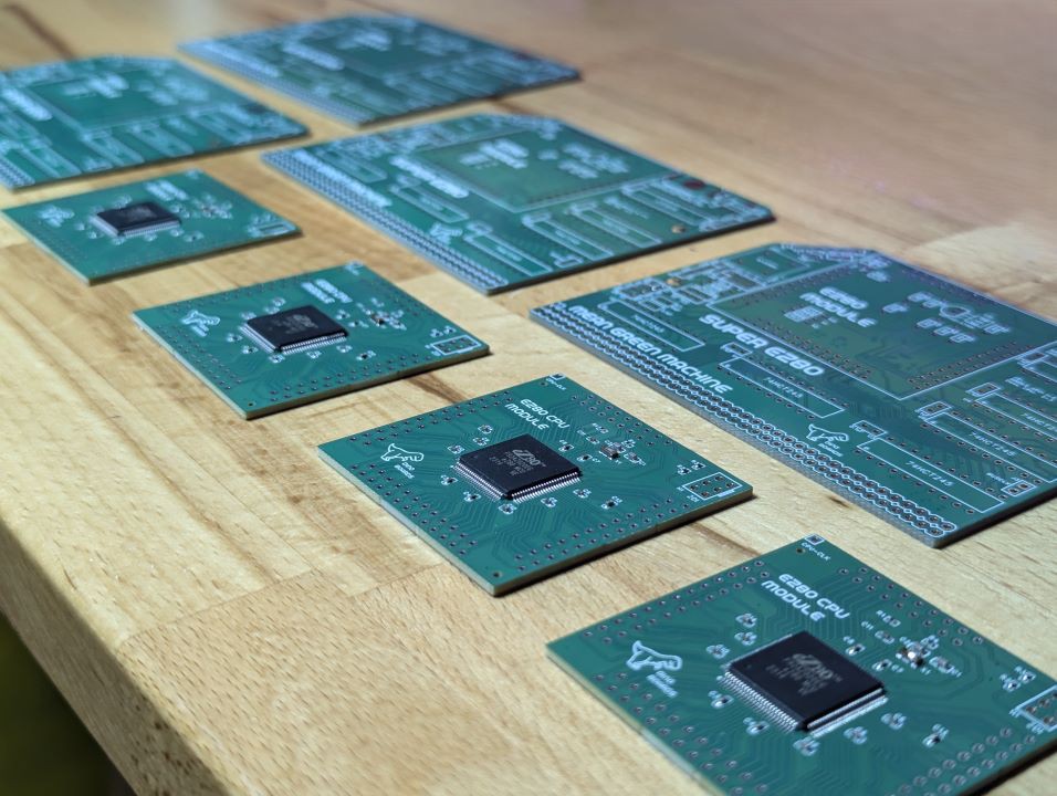
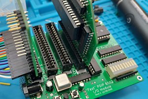
    Last week, I submitted to the PCB manufacturer, an order for assembled CPU modules. This is the first time I have submitted an order to the factory to place and solder components onto one of my PCB designs. It was quick, easy and generally quite simple.

    And now they have arrived.

    Will they work?

    Only one way to find out. Of course, I live on the edge, and ordered a version of the module (and associated interface PCB) with some last minute untested changes.

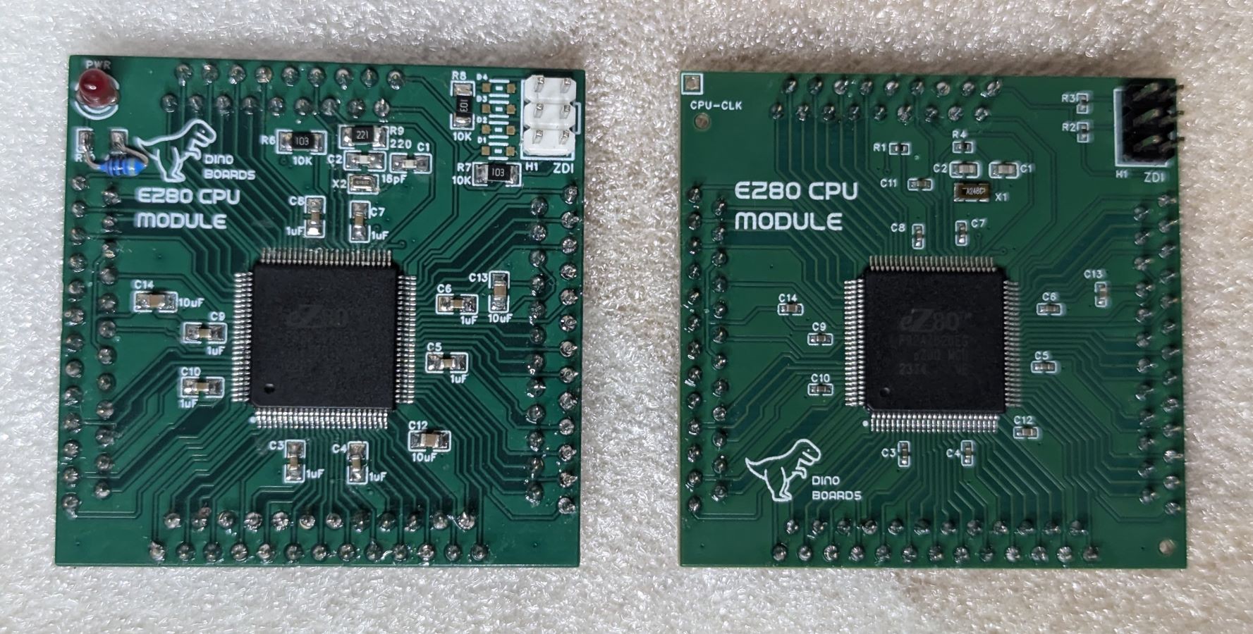
    One change was the size of the various SMD capacitors and resistors. For the hand assembled units, I had selected as large a footprint I could - to reduce the challenge when hand soldering. But for the factory assembled units, it was cheaper and easy to use smaller components. Smaller sizes, I gather, are not only cheaper, the de-coupling capacitors would likely have a lower inductance -- meaning they will work just that bit better at absorbing all those high frequency digital spikes.

    The other change was a slight 'correction' to the positioning of the interface pins. The inner rows are now 2.54mm (100mil) from the outer rows. (The original versions had a rows separation of 3mm)

    The factory assembled units only assembled the surface mount components. I still needed to solder the programming header and the 93 PCB pins.

    Me vs Factory

    Here's a comparison of my hand-assembled module (left), and the factory assembled unit (right). Notice the much smaller components:

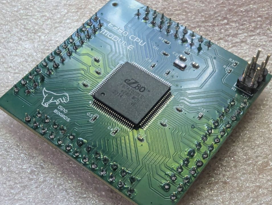
    Close up of the factory assembled unit, after I have soldered in the header and PCB pins:

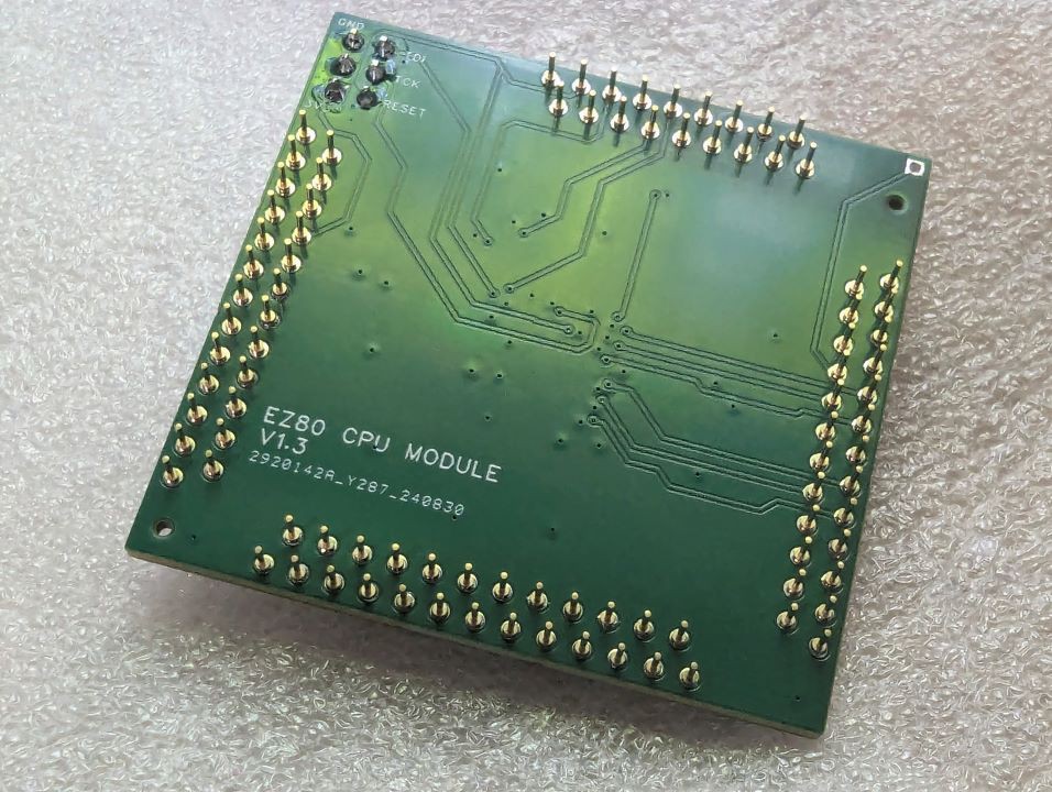
    The back of the module is basically the same:

    I am please to say, I have since installed the new CPU Module and Interface board into my RC2014 and it all works just like the hand assembled units.

  • RC2014/RCBus Mapping

    Dean Netherton09/06/2024 at 04:25 0 comments

    As the eZ80 CPU has some differences and additional control signals, I need to consider how some of these signals have to be mapped, and how their slight difference may impact compatibility. I have already had to 'resolve' issues with the timing of the WR signal to ensure operation of the Bank Memory module and the Compact Flash module.

    Many people have installed various alternative CPUs into their RC2014/RCBus based systems, from the various Zilog processors (Z180, Z280) and Intel 8080 to CPUs with very different timings and signals, such at the 6502. The eZ80 is now, just another CPU for the platform.

    On the electrical front, the eZ80 operates at 3.3V, but is 5V tolerant.  The interface module I have built, uses a number of 74HC245 buffer chips to step-up all outgoing signals to 5V.  The frequency of these signals are going to be higher and have a much quicker rise and fall times compared to a stock Z80 system.  In all my testing to date, I have the eZ80 configured to operate in Z80 Bus Mode.  So in theory, an eZ80 operating at 20Mhz will drive the Address and Data Buses at a similar rate as a Z80 operating at 20Mhz - although its not quite that simple.  (Of course the eZ80 will still run at full speed when operating from its on-chip RAM/ROM, and combined with the chips ability to execute more instructions per clock cycle -- we will still have a very fast processor compared to a standard Z80)

    Nonetheless, any CPU operating at 20Mhz will typically exceed the operating timings requirements for many RC2014/RCBus modules.

    The eZ80 can be configured, as mentioned, to operate its Address, Data and Control Bus in various 'Modes' of operation.  It can be configured to its default eZ80 Mode, or a 'compatible' Z80 Mode, or if you wish, an Intel or even the very different Motorola Mode.

    In the default eZ80 Bus Mode the CPU's reads and writes can be conducted within a single clock cycle.  Compared this to the Z80 mode, where the reads/writes are conducted over at least 3 clock cycles.  Of course, the targeted memory, or I/O device, can send a WAIT signal back to the CPU, extending the time taken for any transfer.  But this requires the memory to be able to trigger that WAIT signal before the CPU has moved onto the next cycle.  A lot of retro modules use older chips that could not possibly operate at these data rates.  Even the modern memory chips (AS6C4008 SRAM) typically used in the RC2014/RCBus systems will struggle at this rate.

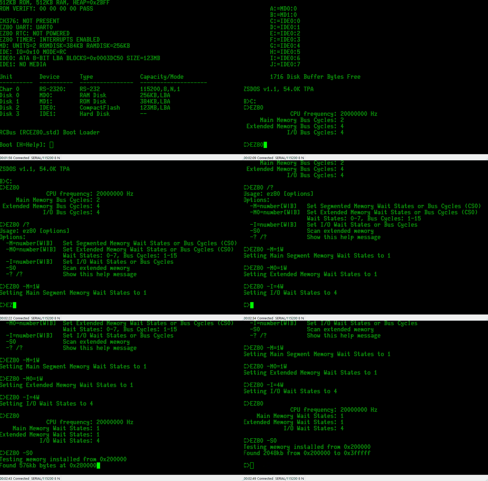
    Thankfully, the eZ80 can also be configured to include its own additional WAIT states.  So with the appropriate configuration, we can drive our Memory and I/O devices at a rate that is kept within the required timing specifications.

    The modes are configured through the use of the eZ80's Chip Select signals (CS0, CS1, CS2, CS3).  Each of these CSx lines can be configured to only be activated for specific address ranges. For example, I have configured CS3 to use *Z80 Compatible Bus Mode* and only activate when a memory read or write happens in the address range of 0x030000 to 0x03FFFF.  And configured CS2 to also use *Z80 Compatible Bus Mode* and activate when an I/O request happens in the address range of 0xFF00 to 0xFFFF.

    The eZ80 to RC2014/RCBus mapping

    Below is a brief description of some of the key signals on the RC2014/RCBus backplanes and the eZ80 equivalent and any differences.

    A0-A15 and D0-D7

    These signals are as expected; the address from the CPU and the bi-directional data bus.

    19 M1

    The eZ80 does not have an M1 signal - it has INSTRD (instruction read) signal.  For simplicities sake, I have not mapped this line -- I just pulled it high with a 10K resistor.

    21 - Bus Clock

    My eZ80 CPU module has an onboard oscillator.  I have tested oscillator's with frequencies from as low as 7.3728MHz up to the CPU's rated 20MHZ and overclocked to 32Mhz.  But I don't send this clock...

    Read more »

  • eZ80 i2c Interface

    Dean Netherton08/18/2024 at 06:02 0 comments

    Been learning about i2c over the last few days.  Today I managed to get the eZ80's i2c interface to drive a little Adafruit 8x8 LED matrix i2c module.

  • Video Evidence

    Dean Netherton08/17/2024 at 02:40 0 comments

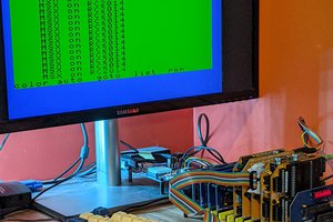
    Thought I should share a quick little demo video, showcasing some of the progress with porting RomWBW to the eZ80 CPU.

    The RC2014 system is configured with:

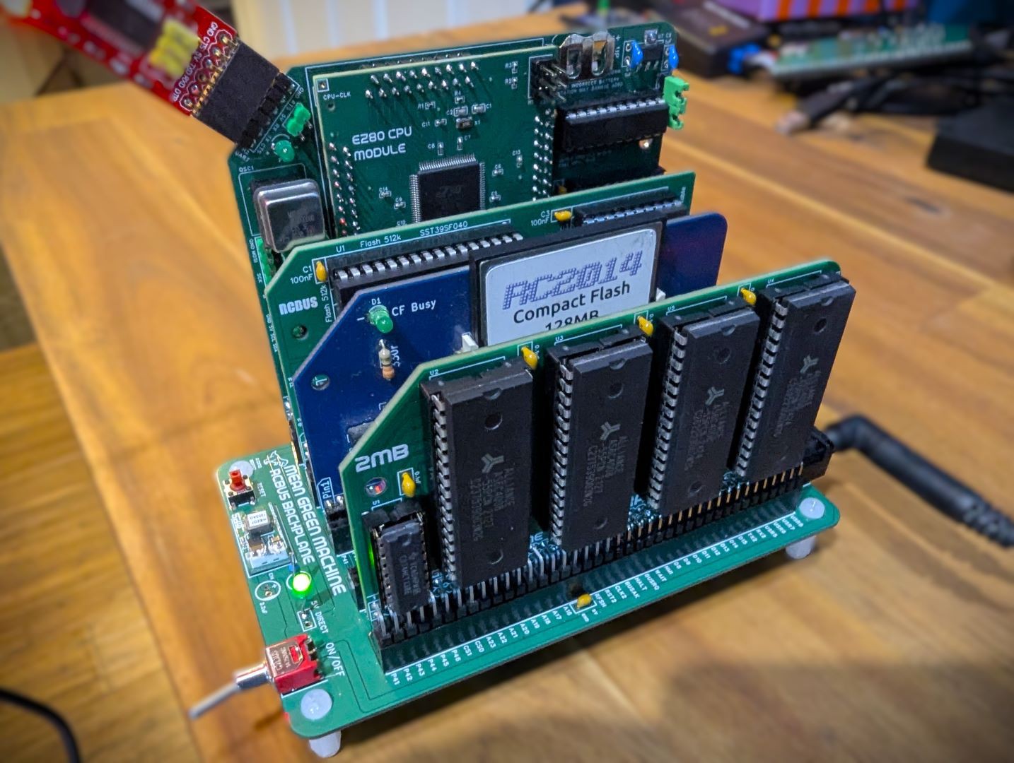
    1. The Official RC2014 Backplane Pro
    2. The Official RC2014 512k ROM 512k RAM Module
    3. The Official RC2014 Digital I/O
    4. My Yellow MSX V99x8 Video Module
    5. My Yellow MSX Keyboard Module
    6. J. B. Langston's SN76489 Sound Card for RC2014
    7. WD37C65 Based Floppy Adapter*

    * Can not remember where I got this module from, but its based on Dr. Scott M. Baker's design.

    The Video shows me using RomWBW, via the MSX Keyboard and Video modules, to load some CP/M applications from a floppy disk.


  • Power on reset

    Dean Netherton08/11/2024 at 02:22 0 comments

    One issue I hit when I was attempting to port the V9958 driver code (TMS9918 compatible driver), was an apparent intermittent fault. After a few frustrating hours, I figured out that the V9958 was not being 'reset' on power up - and could not be initialised correctly by the CPU.

    I think the V9958 is very fussy on requiring that its held in RESET during power-up. If not, it will be in a state that does not seem to be correctable in software.

    I realised that I forgotten to include a Power-On-Reset circuit in my design.

    A quick work around is to press the RESET button on the backplane after initial powering on the kit.

    The original RC2014 Dual clock module does include a Power-On-Reset circuit, but this module is not required for the eZ80 Interface module as it has its own high speed clock on board.

    I have drafted a new PCB design that includes a Power-on-Reset facility; this should ensure the whole system is held in RESET state for a few milliseconds when its initially powered on, and allow the V9958 to initialise itself correctly.

View all 28 project logs

Enjoy this project?

Share

Discussions

mustower wrote 10/01/2024 at 17:54 point

Hi Dean,
thanks for your answer. I've looked closely at everything on https://github.com/dinoboards/ez80-for-rc/, but I just don't understand the boot sequence.
Is the HBIOS ROM plugged into the 512K RAM/ROM module and can then be accessed at address 0x03xxxx?
I noticed that the schematics were not in sync with the software.
e.g. ez80-cpu-1.7.pld shows that EZ_X0 and EZ_X1 are no longer needed.
However, these signals can still be found in the schematics.
Likewise, EZ_XRD and EZ_RD are no longer needed as EZ_RD is probably mapped directly to the Bus.
You write in your answer that CS3 is mapped directly to MREQ, but in the schematics CS3 is mapped to EZ16_MREQ and EZ_MREQ from the eZ80 is mapped to 24MREQ via U6 and then placed on the Bus on User signal D8. It's difficult for me to understand and it confuses me.
I find the project really interesting. I've already written that I would like to recreate it.
I think it's good that you want to offer it on Tindie, but some Tindie sets cannot be delivered to Germany, but that's where I live.
I will have to be patient and wait for your update.

Cheers

Hajo

  Are you sure? yes | no

Dean Netherton wrote 10/01/2024 at 22:07 point

Hi Hajo,

I am very sorry - I had some old versions of the schematics on the site - apologies.  I have since updated them - now i understand some of the confusion i was creating...

Latest versions available at: https://github.com/dinoboards/ez80-for-rc/tree/main/hardware

In that version you can see the CS3 for the eZ80 (EZ_CS3) is directed to one of the buffers (U6), and from there mapped to the MREQ.

> ...but I just don't understand the boot sequence.Is the HBIOS ROM plugged into the 512K RAM/ROM module and can then be accessed at address 0x03xxxx?

Essentially yes ..


When power is first applied, the eZ80 boots up, and starts from address 0x000000 - the code for that is in vectors16.asm (line 51, `reset:`)

It then jumps to __init.  This routine will initialise all the internal on-chip ports and configure CS2 and CS3 to their initial configuration.  CS3 is configured to activate for any memory access in range 0x03xxxx.

__init then passes to __main (in file main.s) where further initialisation is performed.  Things like internal timers are configured, the UART and its buffers are setup etc.

Then it eventually get to the code on line 30 of `main.s`


        LD      A, Z80_ADDR_MBASE               ; set MBASE to $03
        LD      MB, A
        JP.SIS  0

This is where we jump to RomWBW code.  The eZ80 is configured to run code at address 0x030000 in Z80 Mode.  RomWBW will not "see" the 0x03 upper byte of the address, as we are in Z80 mode.  The MBASE register is used for the upper byte of the address.  So now, normal 16bit Z80 code can executed.  All 16 bit jumps and calls within RomWBW will say within the 0x03xxxx address range.

---

In regards to sending kits to Germany, I have delievered some of my Tindie products to Gemany.  I cant say if the receiptants needed to pay any duties on receipt of the goods - but they got them.

I am looking also at list (no time frame yet) also on lectronz.com, where the corect processing of VAT is done.

Hope this helps

Dean

  Are you sure? yes | no

mustower wrote 09/30/2024 at 15:12 point

I am very interested in this project. I would like to build such a system. However, I don't understand the memory mapping of the entire system. /CS0, /CS1 and /CS3 are also applied to user signals of the RC2014 bus. But I can't find any information on how to address the RC2014 512K RAM/ROM card. I think the Memory-Card has to be modified somehow. Where in the eZ80 address space is the ROMWBW ROM  and RAM mapped ?
I would appreciate an answer.
Hajo

PS. Mail contact would be great.

  Are you sure? yes | no

Dean Netherton wrote 10/01/2024 at 04:49 point

Sorry think reply got posted incorrectly....
----

Hello,

Thanks for the interest in my little project.

You may be interested in the github repo that contains much of the project code (and schematics).  https://github.com/dinoboards/ez80-for-rc/tree/main/hardware

I am in the process of documenting the solution and build steps. etc.

For my design, no need to change the 512K RAM/ROM Module - or any other module.

CS3 is mapped to memory MREQ on the RC2014 bus, and is configured for addresses 0x03xxxx (with appropriate wait states applied)

The IORQ eZ80 line is mapped to the RC2014 bus's IORQ -- and CS2 is configured for IO - and is mapped to address range 0xFFxx

CS1 and CS0 are mapped to some spare RCBus lines - in expectation of a future module that can support 24 bit memory addressing.

I intend to list this as a kit on my Tindie store as soon as I can.

Cheers

Dean

  Are you sure? yes | no

Similar Projects

Does this project spark your interest?

Become a member to follow this project and never miss any updates