Close
0%
0%

Swirl Dice

A Moving Magnet based Dice Roller

Public Chat
Similar projects worth following
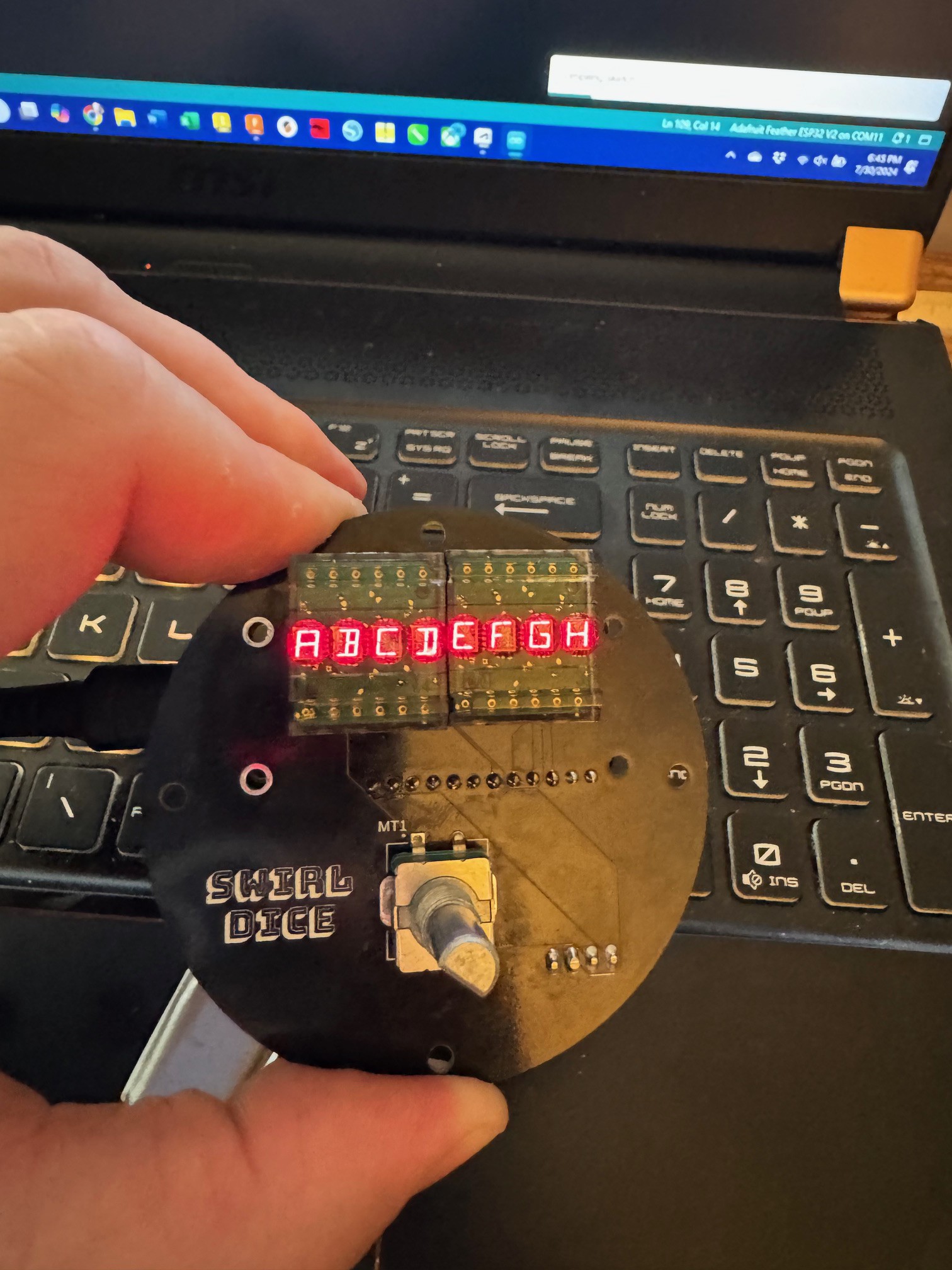
This handheld dice roller uses a 3-Axis magnetometer to generate random numbers which are mapped to a chosen number of sides. A rotary encoder allows selection of the number of sides and whether to roll with advantage/disadvantage or straight.

Initial Idea

My previous dice project Radiant Dice used a Geiger Counter and a radioactive source to make true random numbers. It looks and works great, but it's a bit bulky. I wanted to make something handheld that would have a physical interaction to create the rolls.

I saw the 3D magnetometer on Adafruit, and I thought that might fit the bill for way to generate the numbers. I got a big cylinder magnet to give add to the physical interaction. I had some HDPL1414 displays that have been waiting for a project, and this seemed like a good choice.

With the initial mechanism in place, I started to prototype my way through the project.

Body Design

I went for a hi-fi aesthetic with the metal knob, wood body and acrylic plates. I did the CAD in Inventor. I did the 3D printing of prototypes on a Prusa i3 Mk3.9, and used a 60w Epilog laser cutter. I am going to cut the wood parts on my X-Carve router.

Electronics

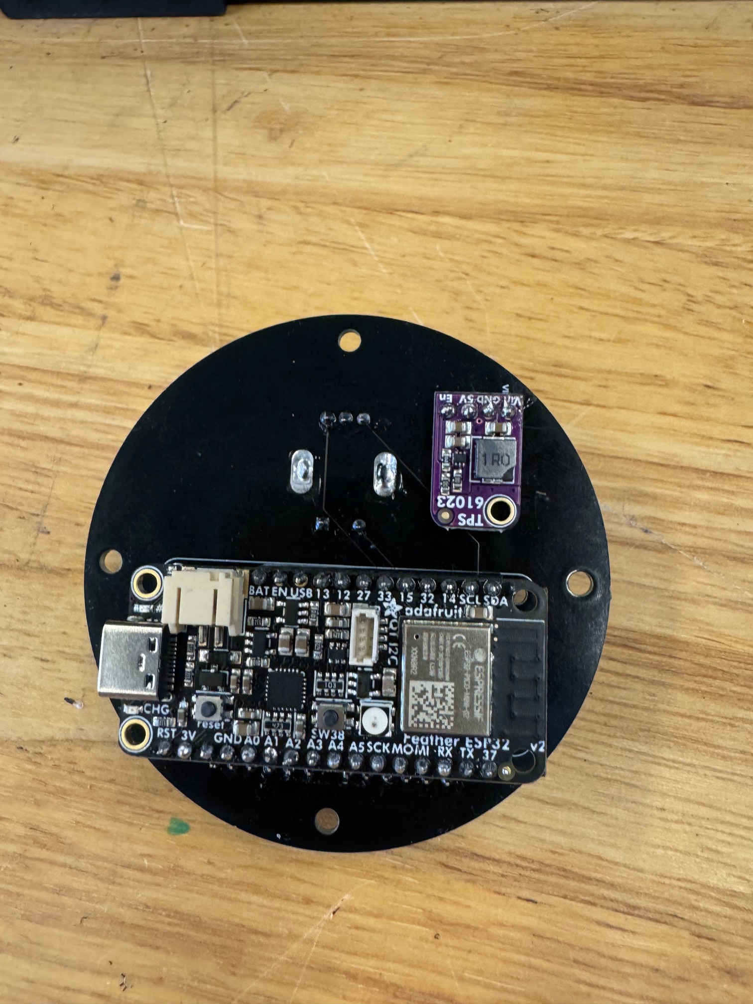
For micro, I went with a  ESP32 V2 Feather. It had the battery circuit built in, had a STEMMA QT port on top. Eventually, it would be nice to have an app collect the rolls so it could perhaps be used with a VTT or to share with the DM.

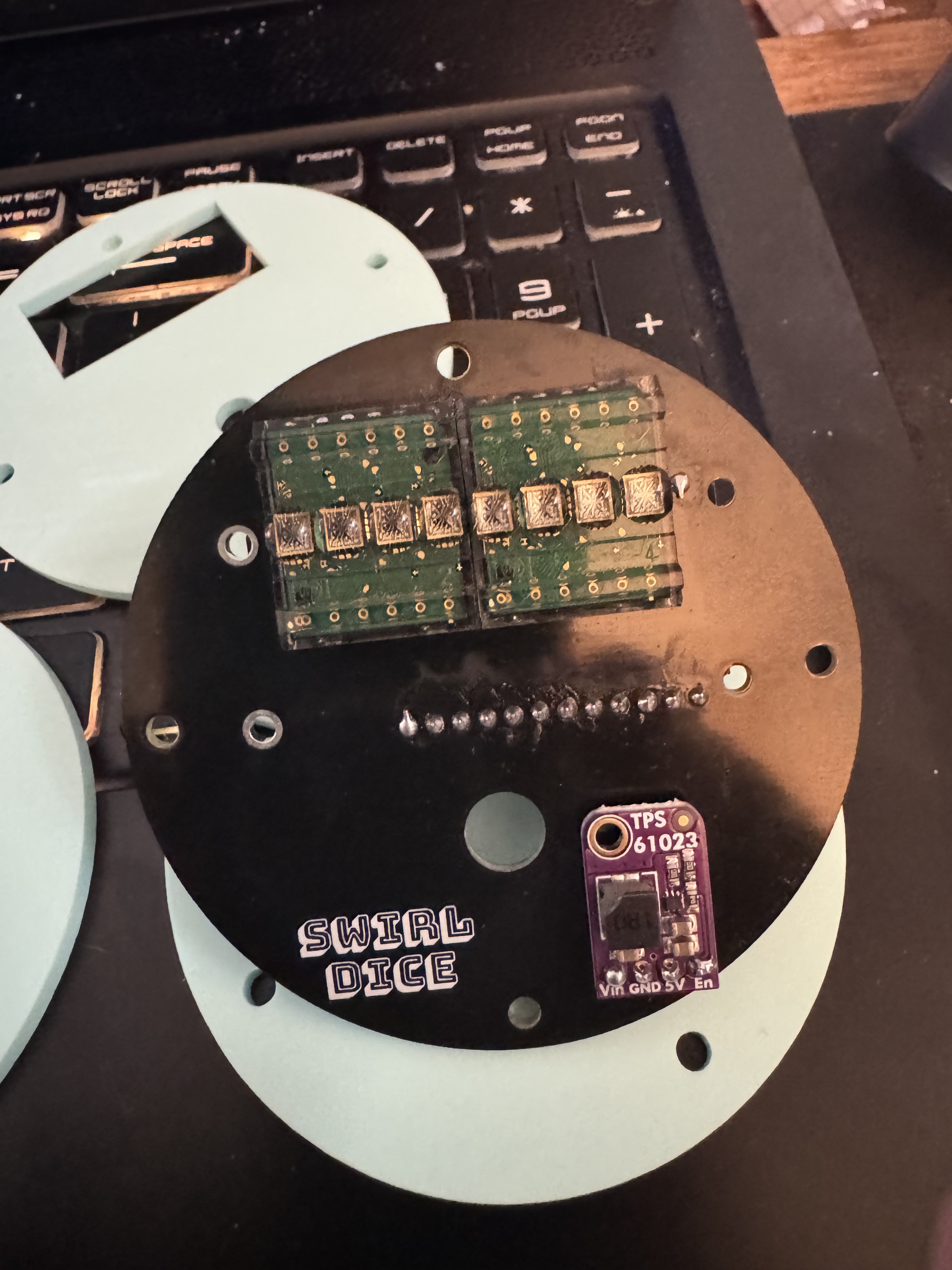
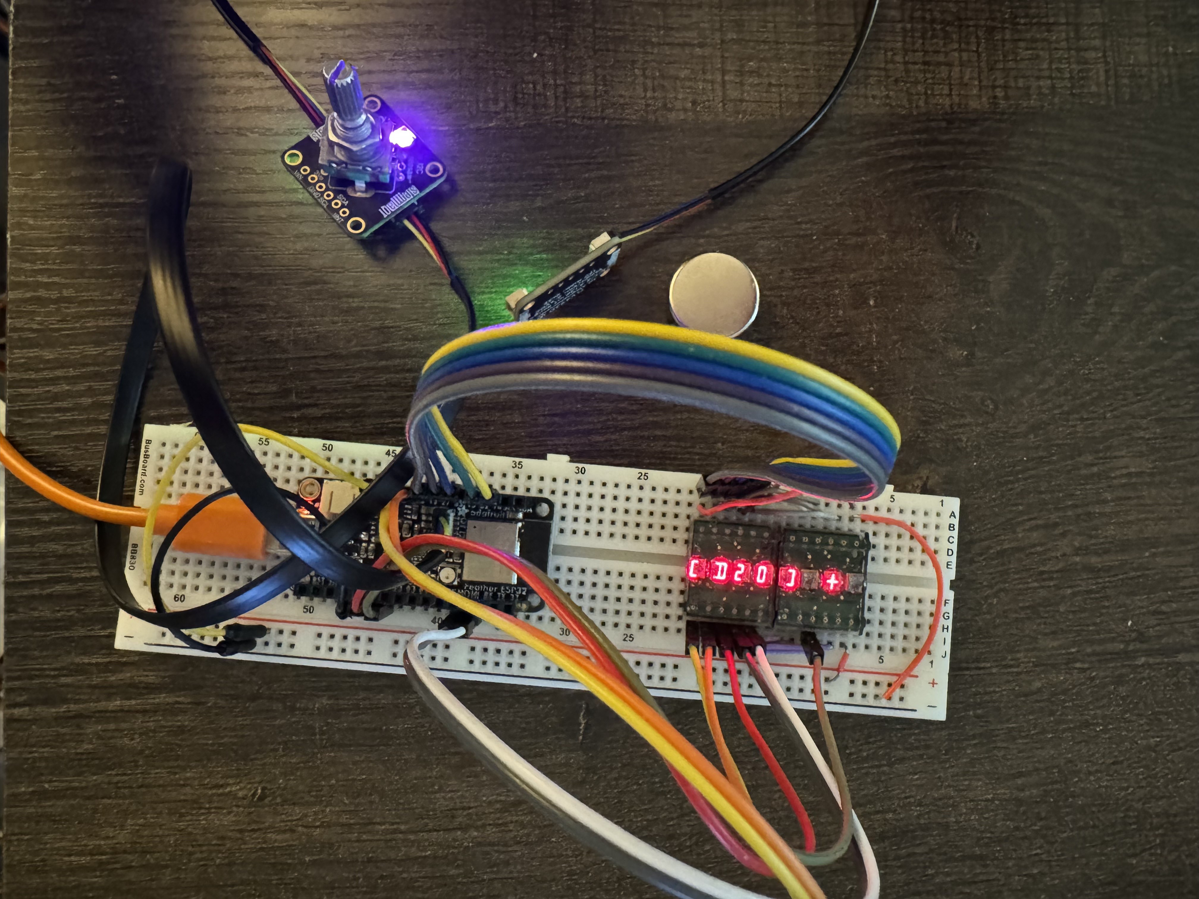
The  HPDL1414 displays, they are alphanumeric  which makes them more flexible than 7-segment displays. They are from the 90s, but not too hard to get a hold of currently. The encoder was also pretty straight forward to incorporate. I started using the Adafruit STEMMA QT Encoder breakout, but it didn't fit in the case, so I put the encoder directly on the board.  I am not an electrical engineering, but I have been working with custom circuit boards to replace wires. I did not consider trace thickness or include passives (beyond the two resistors) that may be required. 

Random Number Generation

I'm using the amount (distance) from the sensor and the polar angle values from the sensor multiplied by 100 to make them integers (keeping the precision) modded by the number of sides. I have done a couple thousand of readings, and them numbers were even though more testing is needed. 

(((distance + polarAngle) * 100) % numberOfSides) + 1

Swirl Dice Acrylic v3.svg

Laser Cutting File for the Acrylic Plates

svg+xml - 9.13 kB - 08/12/2024 at 15:25

Preview

Swirl Dice Shell v5.stl

3D printing files for the full stack.

Standard Tesselated Geometry - 868.44 kB - 08/11/2024 at 02:55

Download

swirlDice_code_v3.ino

This version senses movement of the magnet and automatically goes into the rolling mode.

ino - 4.95 kB - 08/10/2024 at 23:56

Download

Swirl Dice Circuit Board v4.zip

Gerbers for Circuit Boards, I used PCBWay

x-zip-compressed - 34.81 kB - 08/02/2024 at 17:02

Download

View all 20 components

  • New Circuit Boards!

    Andrew Woodbridge07/31/2024 at 05:06 0 comments

    I got the new version of the circuit board in, thanks to PCB Way. Who made iterating fast and easy. The components all fit, and I'm happy with how everything lines up.

    The encoder is not reading correctly. Apparently not all the pins on the feather have pullup resistors. Of course I didn't test it beforehand, I did a quick breadboard to test out the encoder with resistors, and that solved the problem. I am adding 2 10k resistors and hopefully ordering the last circuit board..

    The HDPL displays are not happy in pin header sockets their legs are too thin, so I will be reverting to soldering them in when I get the last set of boards.

    Up next is working on the code to be able to trigger a dice roll by moving the magnet.

  • PCB &Acrylic Fit Testing

    Andrew Woodbridge07/18/2024 at 17:17 0 comments

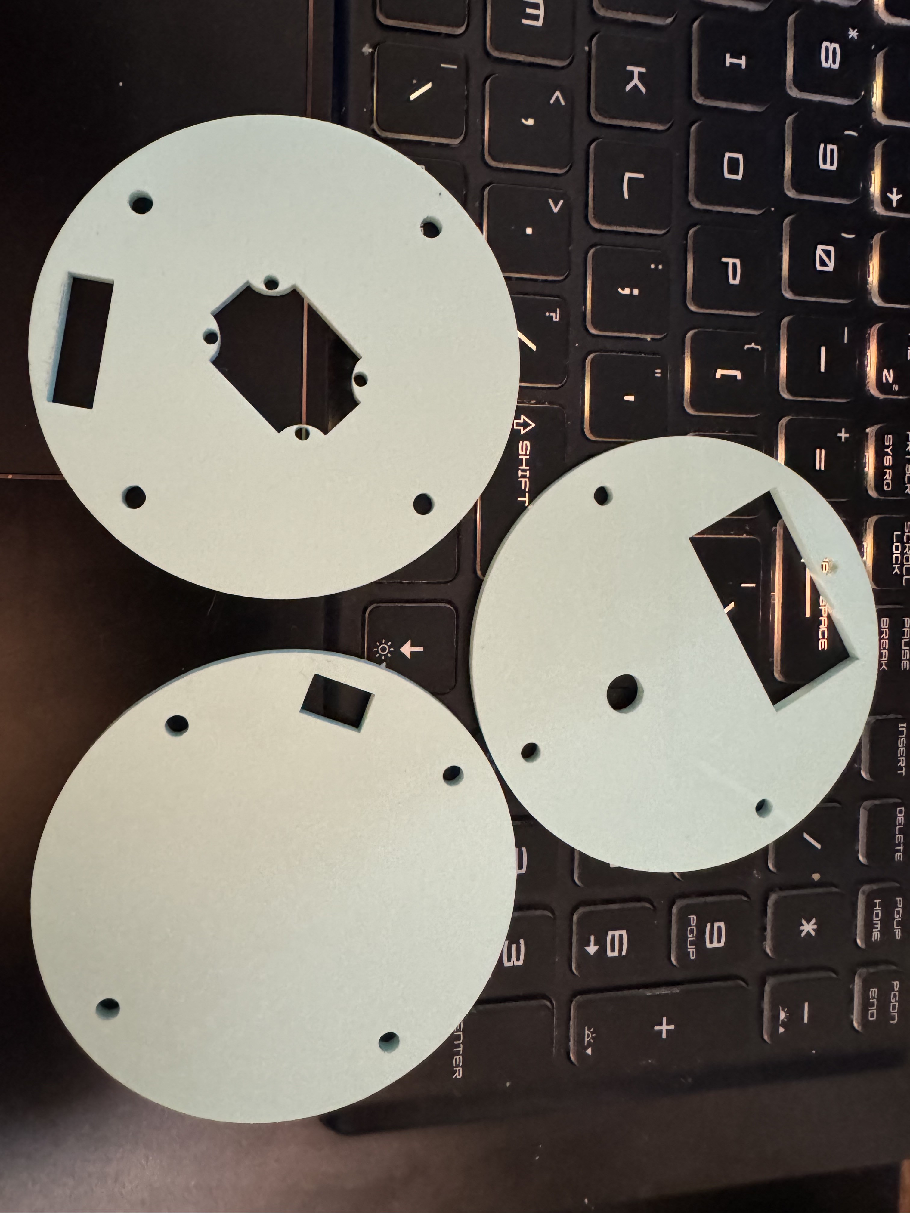
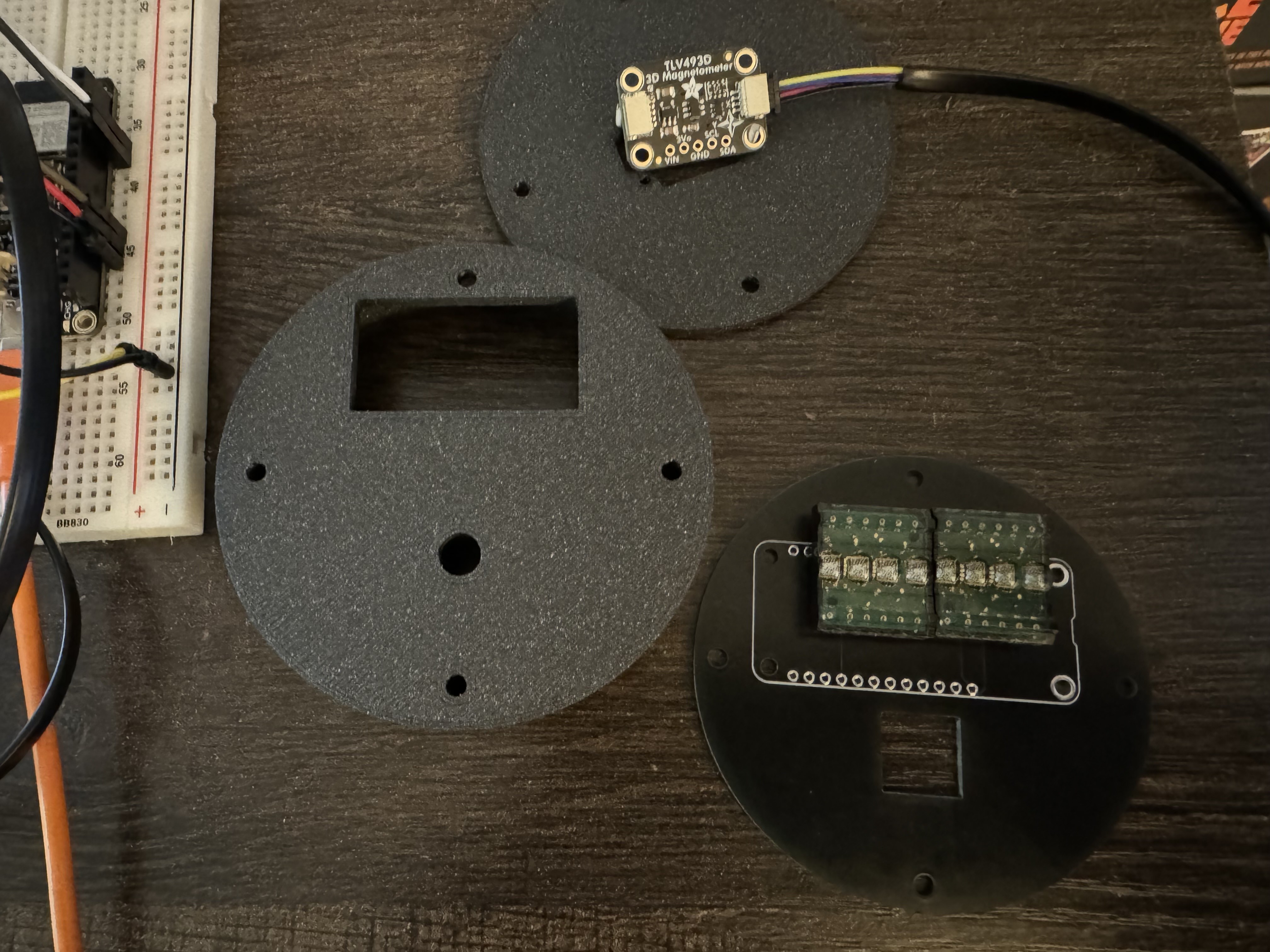
    I did the first test of the laser cut panels, I'm happy with the bottom and  middle panels, the top panel doesn't quite line up with the display. That's an easy fix. The bigger issue is the encoder. I was planning on using Adafruit Rotary Encoder Breakout (to save on GPIO pins), but it just doesn't fit well. with the circuit board below the main circuit board. It interferes with the feather. I will be soldering an EC11 directly to the circuit board. So I will need another iteration of the circuit board, now v3

    I also have a much better feel for the vertical space requirements of the feather. I will need to add some more space for the battery and the tall components of the feather. This will be a fourth layer of acrylic and a third layer 3D printed part (which will hopefully be wood in the final version).

  • Initial Coding & Electronics

    Andrew Woodbridge07/06/2024 at 04:33 0 comments

    The initial code is setup. There are three modes:

    • Sides - How many sides the dice have, D3-D100
    • Advantage/Disadvantage
    • Rolling

    Random Number Generation is currently accomplished by combining amount and distance values from the magnetometer then moded by the number of sides. This method will require further testing for randomness.

    -

  • Initial Component & Case Testing

    Andrew Woodbridge07/06/2024 at 03:59 0 comments

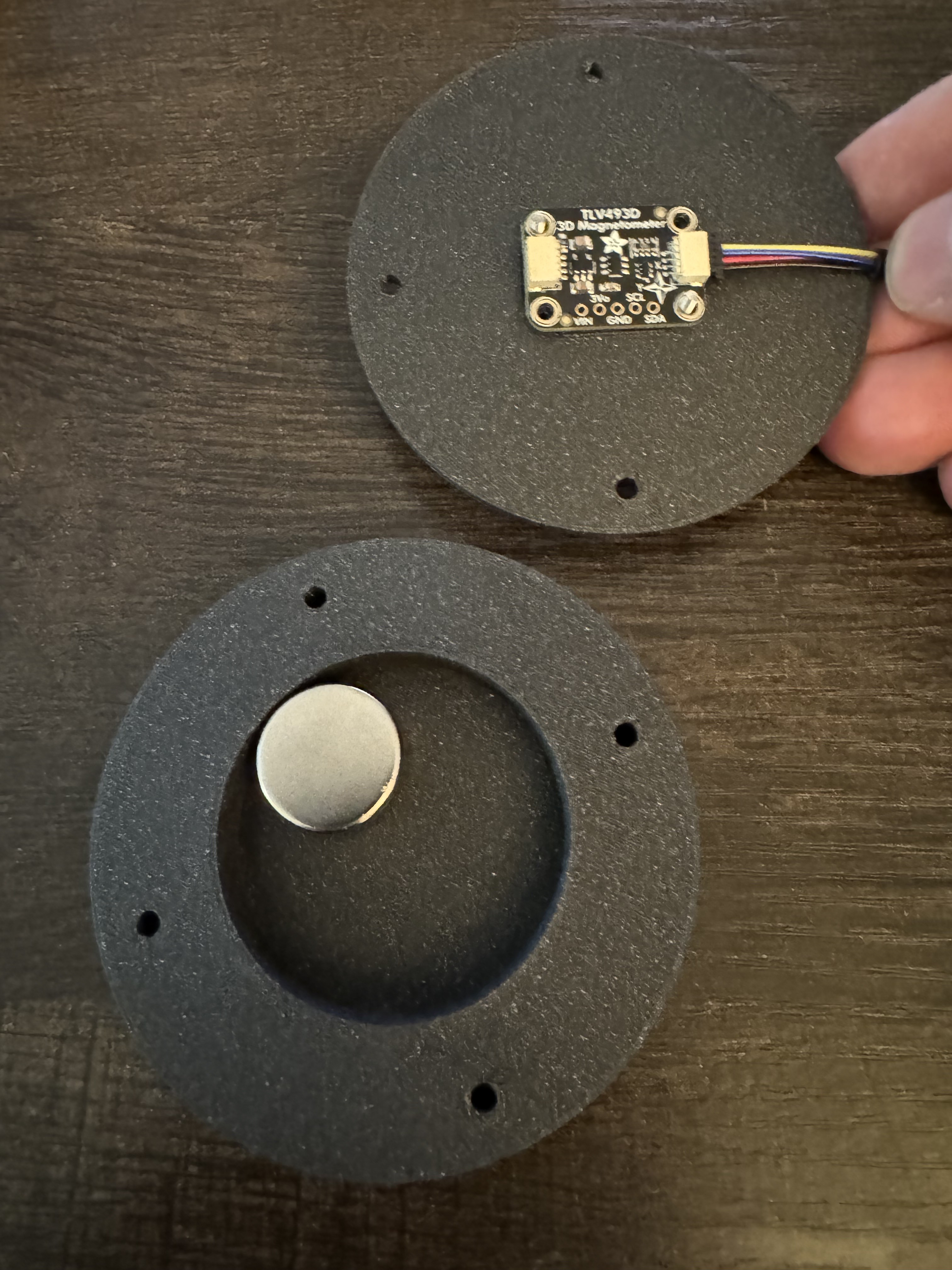
    I 3D printed my initial version of the case. The magnetometer board fits in it's spot, and the magnet fits in it's well, but I expanded the the diameter of the well to get more movement. The M2 button caps interfered with the magnet movement, so I made the well a bit deeper. I also added a space for the power switch

    Revised Version:

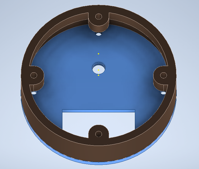
    The upper shell was too thick, so the circuit board didn't fit. So I increased it's diameter a bit. I also spllt the upper section into two pieces. 

    Revised Version:

View all 4 project logs

  • 1
    Order the custom circuit board & parts

    The gerber file attached to the project can be submitted to get circuit boards made. I used PCBWay, it's really easy to do. I kept all the settings except for the board and silkscreen color as the defaults.

    The electronics BOM should pretty easy to get. I included links for the parts I used in the parts section.

  • 2
    Make the body
    •  You can 3D print everything
      • All the parts come as one file. PrusaSlicer has a break into objects button to separate the parts out. I suggest using contrasting colors for the plates and the thicker body parts
    • 3D print the thicker sections and laser cut the plates
      • Break apart the 3D print and delete the four plates. Print the remaining 3 body sections.
      • Use the SVG for the laser cutting. I used acrylic from Cohn which had a matte surface and a glossy surface. If you want the surfaces to match, you need to mirror the bottom panel (it's directional because of the power switch).
    • Mill the thicker sections
      • This is my ultimate goal, I will post details on this process once I test it myself.
  • 3
    Mill/3D Print Mill the Wood Layers

    All the parts come as one file. Prusa slicer has a break into objects button to separate the parts out. If you're laser cutting the acrylic layers, you can delete them.

View all 9 instructions

Enjoy this project?

Share

Discussions

Similar Projects

Does this project spark your interest?

Become a member to follow this project and never miss any updates