-
New Circuit Boards!
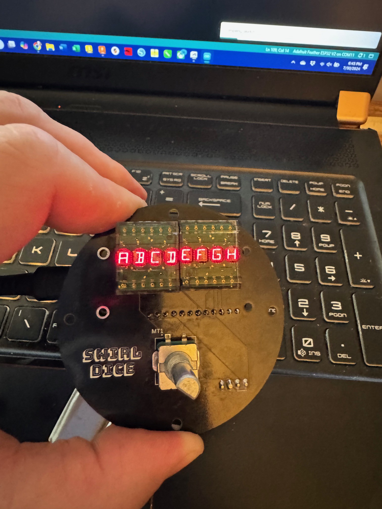
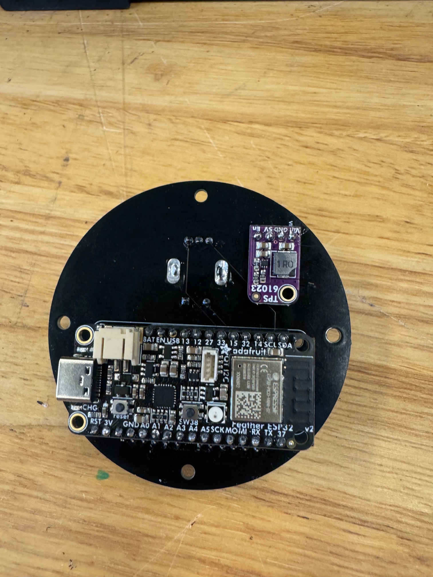
07/31/2024 at 05:06 • 0 commentsI got the new version of the circuit board in, thanks to PCB Way. Who made iterating fast and easy. The components all fit, and I'm happy with how everything lines up.
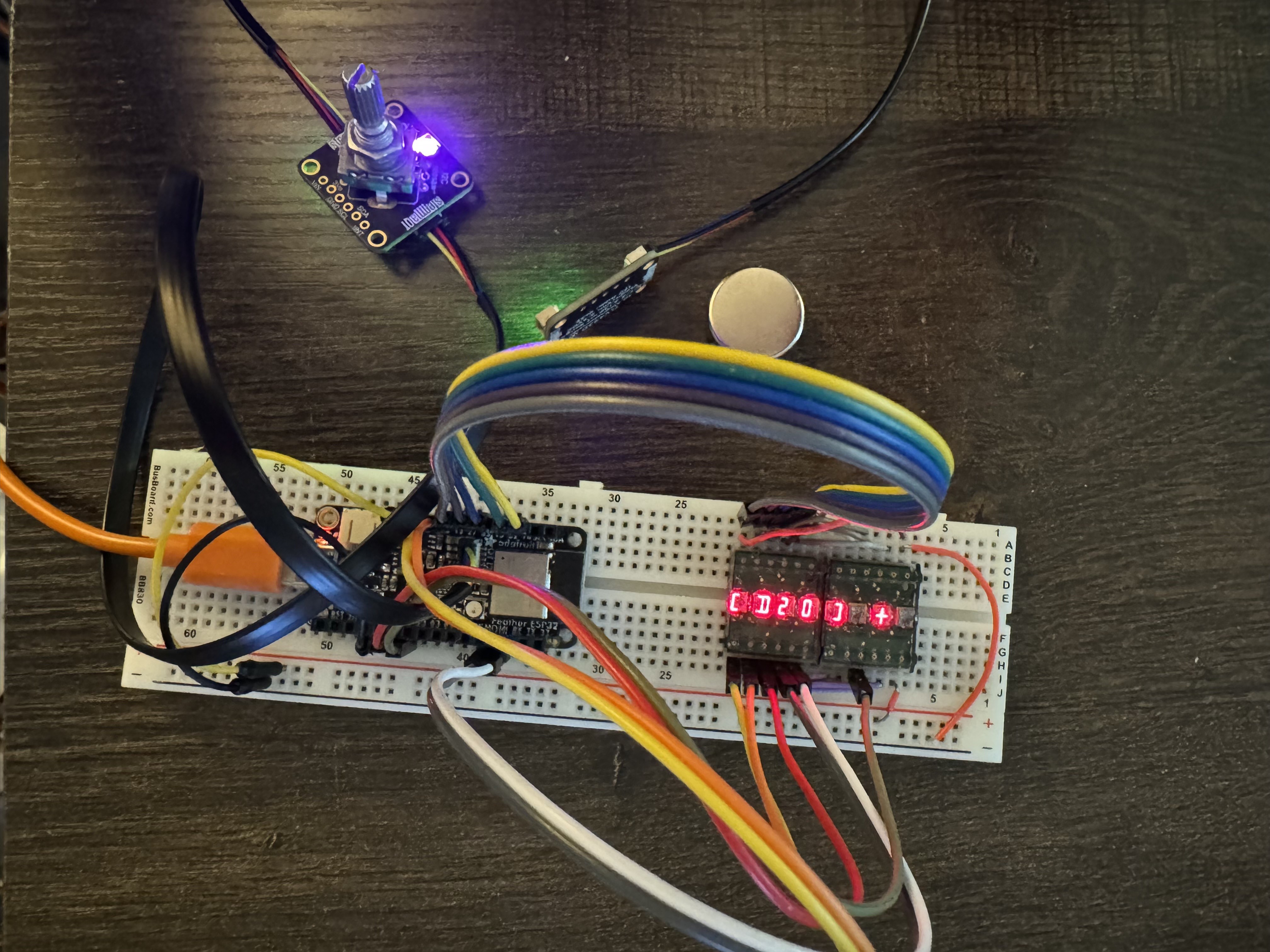
The encoder is not reading correctly. Apparently not all the pins on the feather have pullup resistors. Of course I didn't test it beforehand, I did a quick breadboard to test out the encoder with resistors, and that solved the problem. I am adding 2 10k resistors and hopefully ordering the last circuit board..
The HDPL displays are not happy in pin header sockets their legs are too thin, so I will be reverting to soldering them in when I get the last set of boards.
![]()
![]()
Up next is working on the code to be able to trigger a dice roll by moving the magnet.
-
PCB &Acrylic Fit Testing
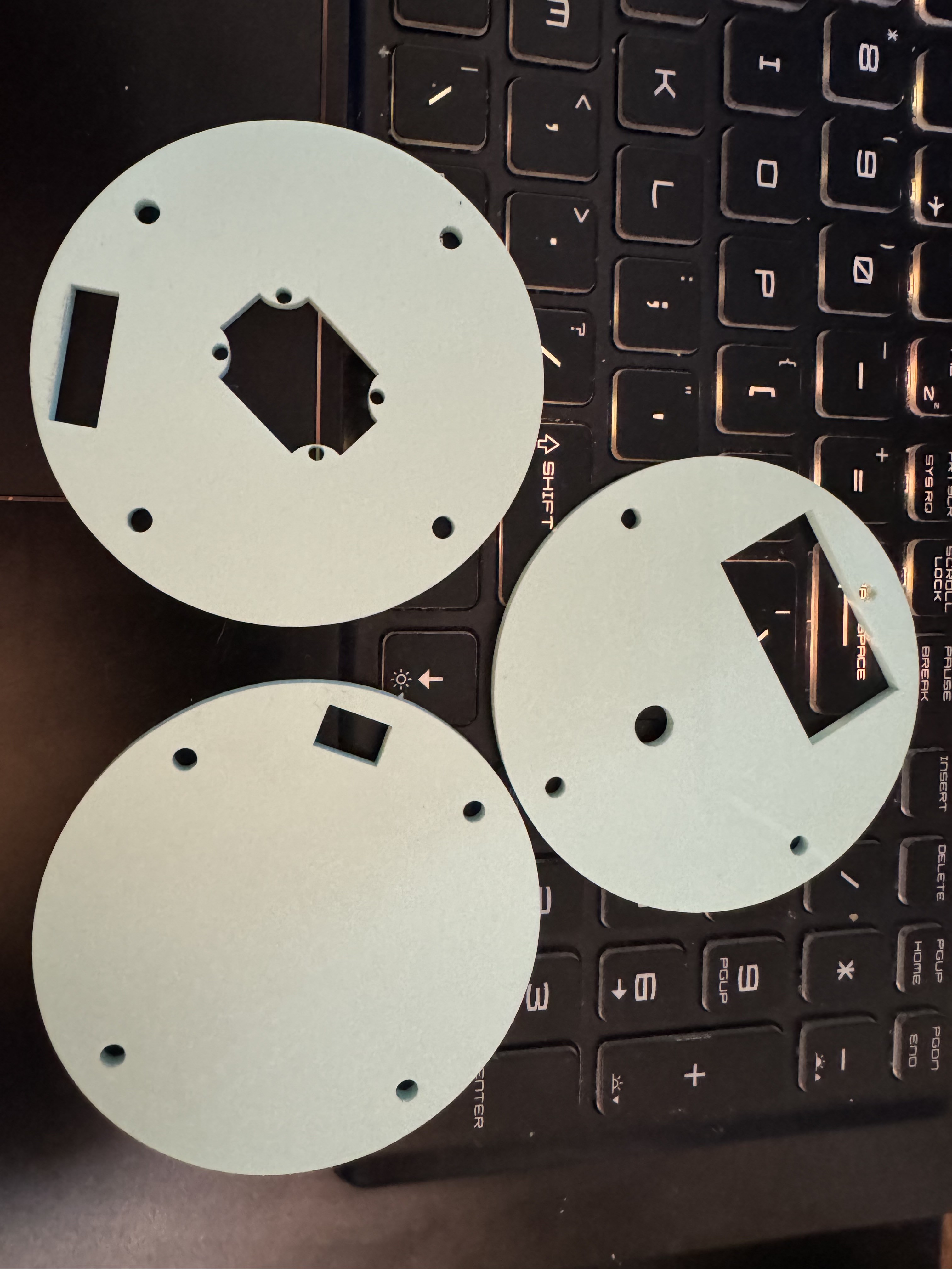
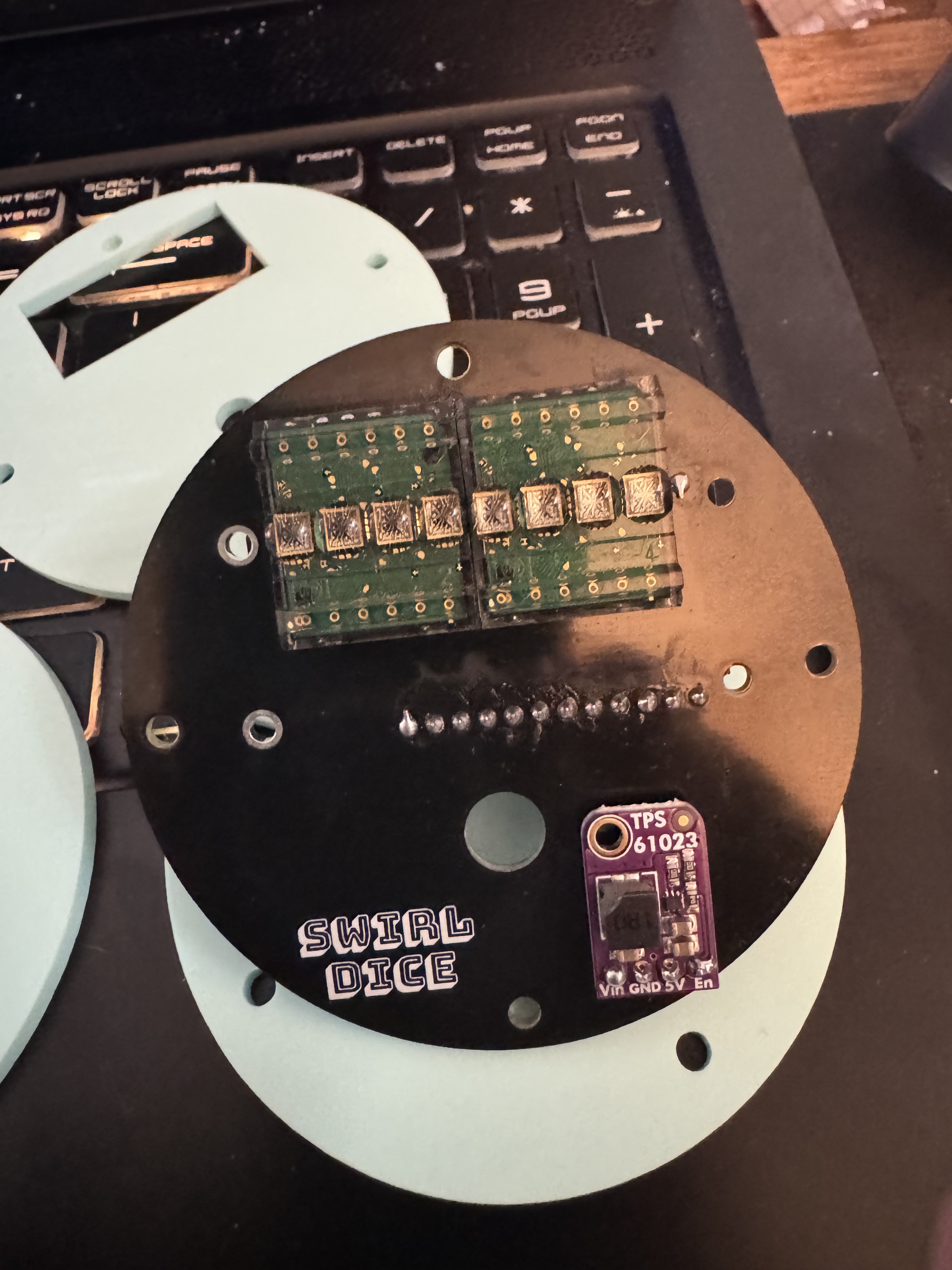
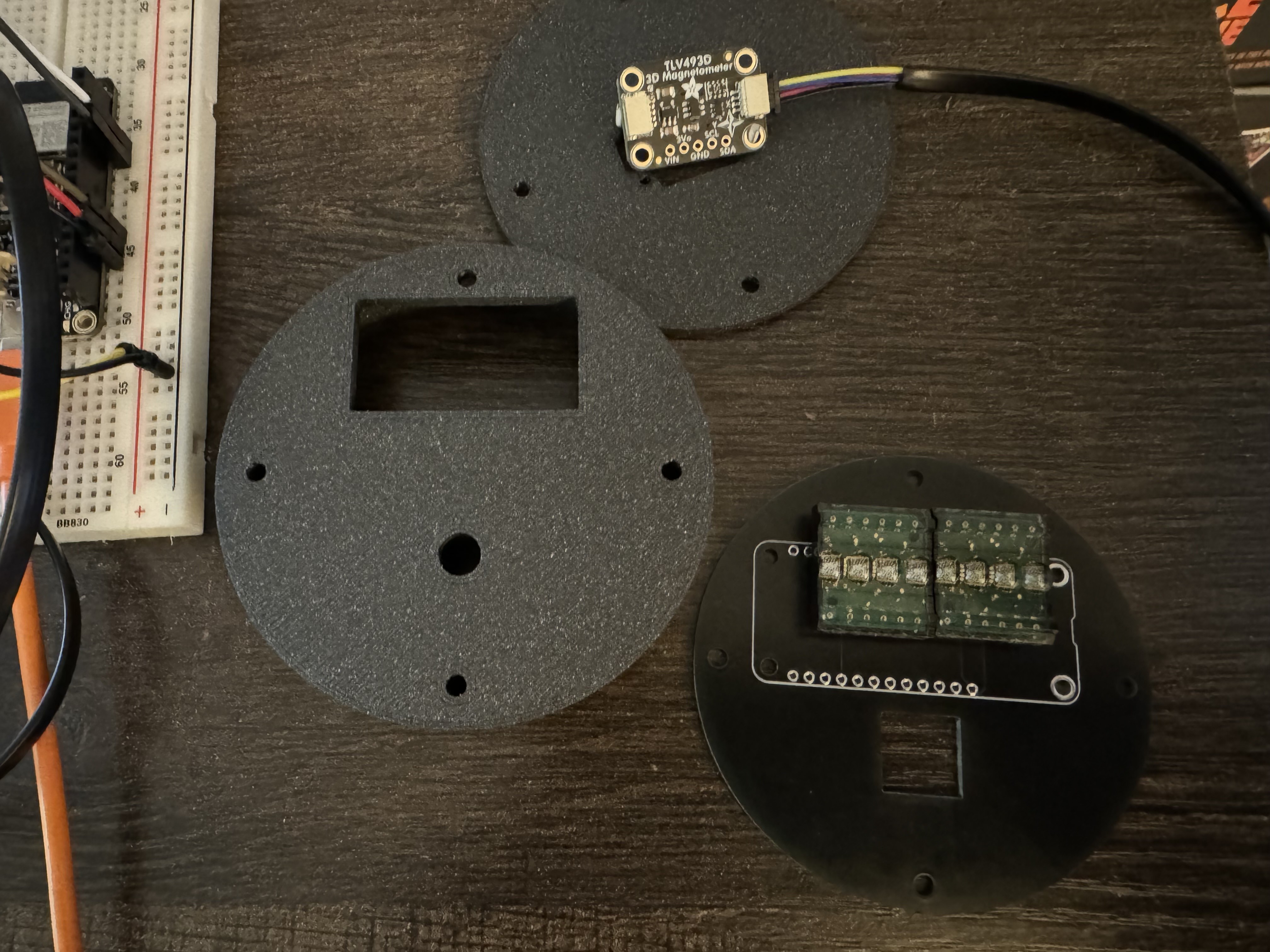
07/18/2024 at 17:17 • 0 commentsI did the first test of the laser cut panels, I'm happy with the bottom and middle panels, the top panel doesn't quite line up with the display. That's an easy fix. The bigger issue is the encoder. I was planning on using Adafruit Rotary Encoder Breakout (to save on GPIO pins), but it just doesn't fit well. with the circuit board below the main circuit board. It interferes with the feather. I will be soldering an EC11 directly to the circuit board. So I will need another iteration of the circuit board, now v3
I also have a much better feel for the vertical space requirements of the feather. I will need to add some more space for the battery and the tall components of the feather. This will be a fourth layer of acrylic and a third layer 3D printed part (which will hopefully be wood in the final version).
![]()
![]()
-
Initial Coding & Electronics
07/06/2024 at 04:33 • 0 commentsThe initial code is setup. There are three modes:
- Sides - How many sides the dice have, D3-D100
- Advantage/Disadvantage
- Rolling
Random Number Generation is currently accomplished by combining amount and distance values from the magnetometer then moded by the number of sides. This method will require further testing for randomness.
![]()
-
-
Initial Component & Case Testing
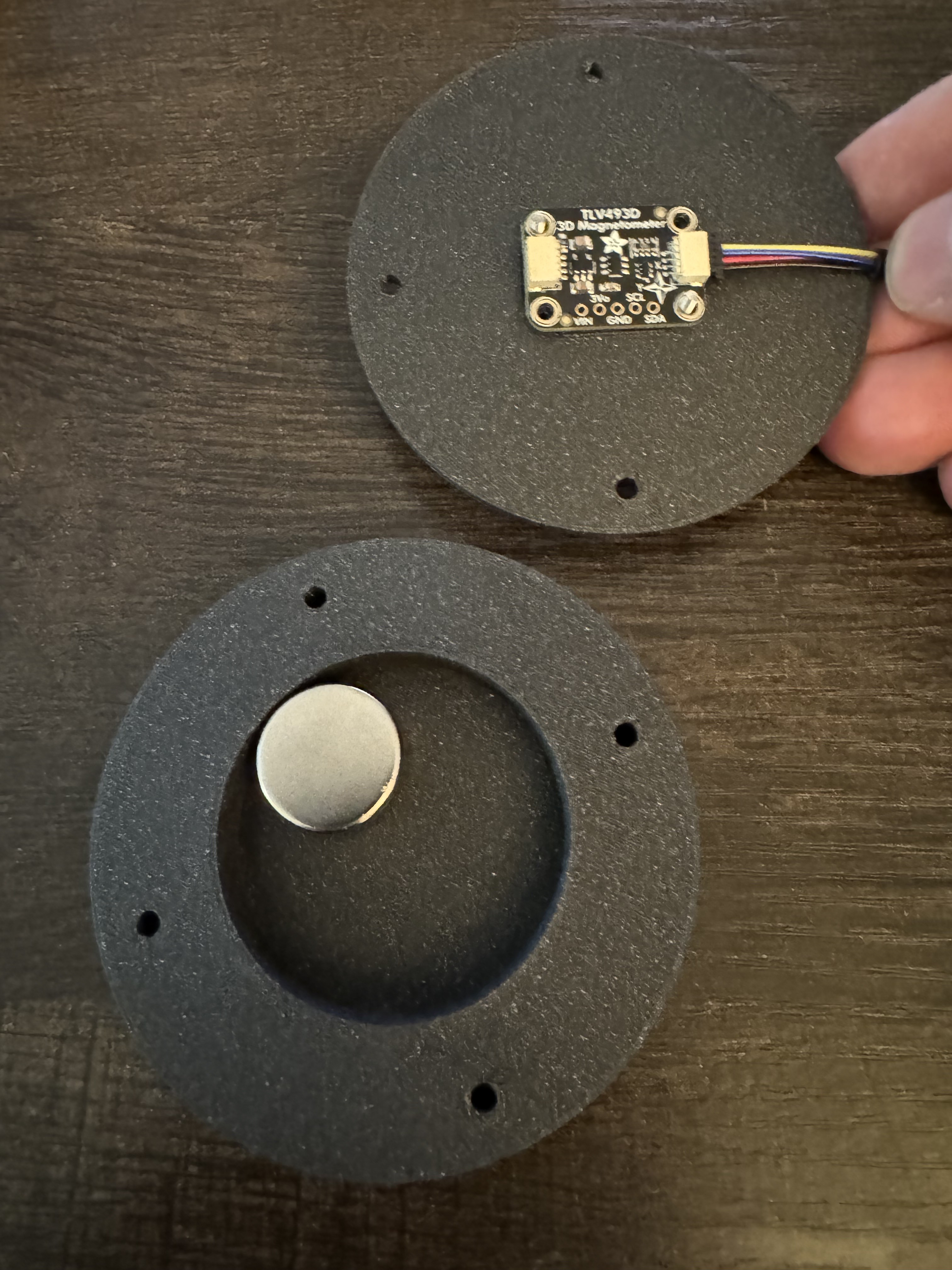
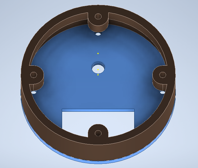
07/06/2024 at 03:59 • 0 commentsI 3D printed my initial version of the case. The magnetometer board fits in it's spot, and the magnet fits in it's well, but I expanded the the diameter of the well to get more movement. The M2 button caps interfered with the magnet movement, so I made the well a bit deeper. I also added a space for the power switch
![]()
Revised Version:
![]()
The upper shell was too thick, so the circuit board didn't fit. So I increased it's diameter a bit. I also spllt the upper section into two pieces.
![]()
Revised Version:
![]()
 Andrew Woodbridge