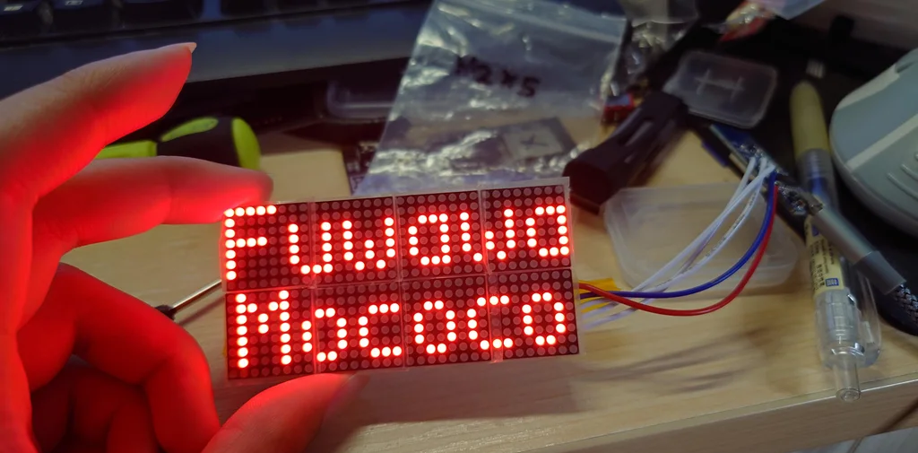
I guess most people had heard of the "Useless box" mechanism. In simple words, it is a motor connected to a switch with some logic gates, when you push the switch to the "ON" position, the robot will start the motor and with the help of a cleverly designed lever and pusher arm, push the switch back to the "OFF" position.
This is a really common toy that many people have already made one and put them on Youtube. It is not considered a really difficult project and it can be easily done by a high school student.
Each year, I challenge myself making a tech product using the tech and skills I learnt that year. This year, I also want to take this chance to create one of my most complex project of the year. That is why I challenge myself to build a Kawaii Useless Robot referencing the design from a Japanese Maker named Kairoshim, who made the world first Kawaii Useless Robot and post it on NicoNico 12 years ago.
Components
1×
3D printed case with PLA (black)
1×
Laser cutted semi-transparent black acrylic (2mm)
1×
Laser cutted black acrylic (2mm)
2×
38mm rubber sealing ring (5mm thickness, for wheels)
This project requires PCBs as this circuits are too complex for wiring with UEW. There are a total of 3 PCBs required for this build. Two of them are designed to be stacked on top of each other and the other one is the main controller that require double side soldering / reflow.
From the front to the back side are the
LED matrix display module with driver ICs
Stepper motor driver ICs with shift register, and FFC connectors for MCU connection
MCU board, which contains the battery charging and boosting to 5V, USB to UART programming interface (via type C) and the main MCU (ESP32E) with SD card (eMMC) as external storage.
All 3 PCBs are printed using 1mm FR4 to save space.
2
Soldering and Assembling the Display Module
Let start with the display module. The display module consists of 8 MAX7219 driver IC and 8 LED dot matrix display. The circuit of this module is identical to those commonly available LED dot matrix modules with 8 units in series.
However, as we are using the 1.95mm LED matrix module here, the relative size of the LED matrix is much smaller than those in the 3mm modules. That is why it is recommended that if you want to hand solder this, make sure you solder it module by module instead of face by face. Which means, you would want to solder one driver IC, then one LED dot matrix module, test it with some code on your MCU and if it works, solder the next set. This helps make sure there are no shots or issue with the soldering, as the IC and the pins of the matrix module is so close, after you soldered the 2nd row of the module, it is pretty much impossible to fix the soldering issue on the first row.
3
Glue Nuts Onto the Back of the Driver Board and Install Switch
Before soldering the board,you can take the chance to glue 3 x M2 nuts on the back of the driver board. This will help with the assembly process later on. After the screws are attached and glues are dried up, you can now install the switch. The switch is held in place with 2 x M2 x 5mm srews on both side of the 3D printed mount as shown in the last photo.
Are you the same guy that made exactly the same device in 2012 ( https://www.youtube.com/watch?v=bOD2-mRphTI )?