Close
0%
0%

Tuba - The Open-Source Glider

creating a blueprint for an underwater glider for hobbyists to explore and study down to a 200m (and later 1000m) of our world oceans

Similar projects worth following
The underwater glider field has experienced a surge of interest in recent years, driven by growing awareness of the oceans and their critical role in our planet’s health. Despite commendable efforts to develop low-cost, open-source gliders, access to this technology remains limited—currently, the only practical option is to purchase a commercial unit, typically costing around $200,000 USD.

My goal is to change that by creating an open, accessible blueprint for an underwater glider that students, researchers, and hobbyists around the world can build, use, and continuously improve. The aim is to enable autonomous exploration and data collection at depths of up to 200 meters—with a long-term goal of reaching 1000 meters—over deployments lasting weeks or even months, without the need for prohibitively expensive commercial systems.

To support this effort, I have also started a wiki dedicated to all aspects of underwater gliders, which is linked below.

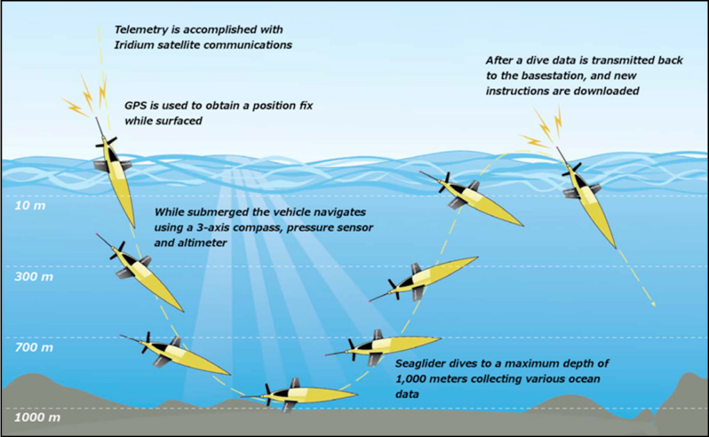
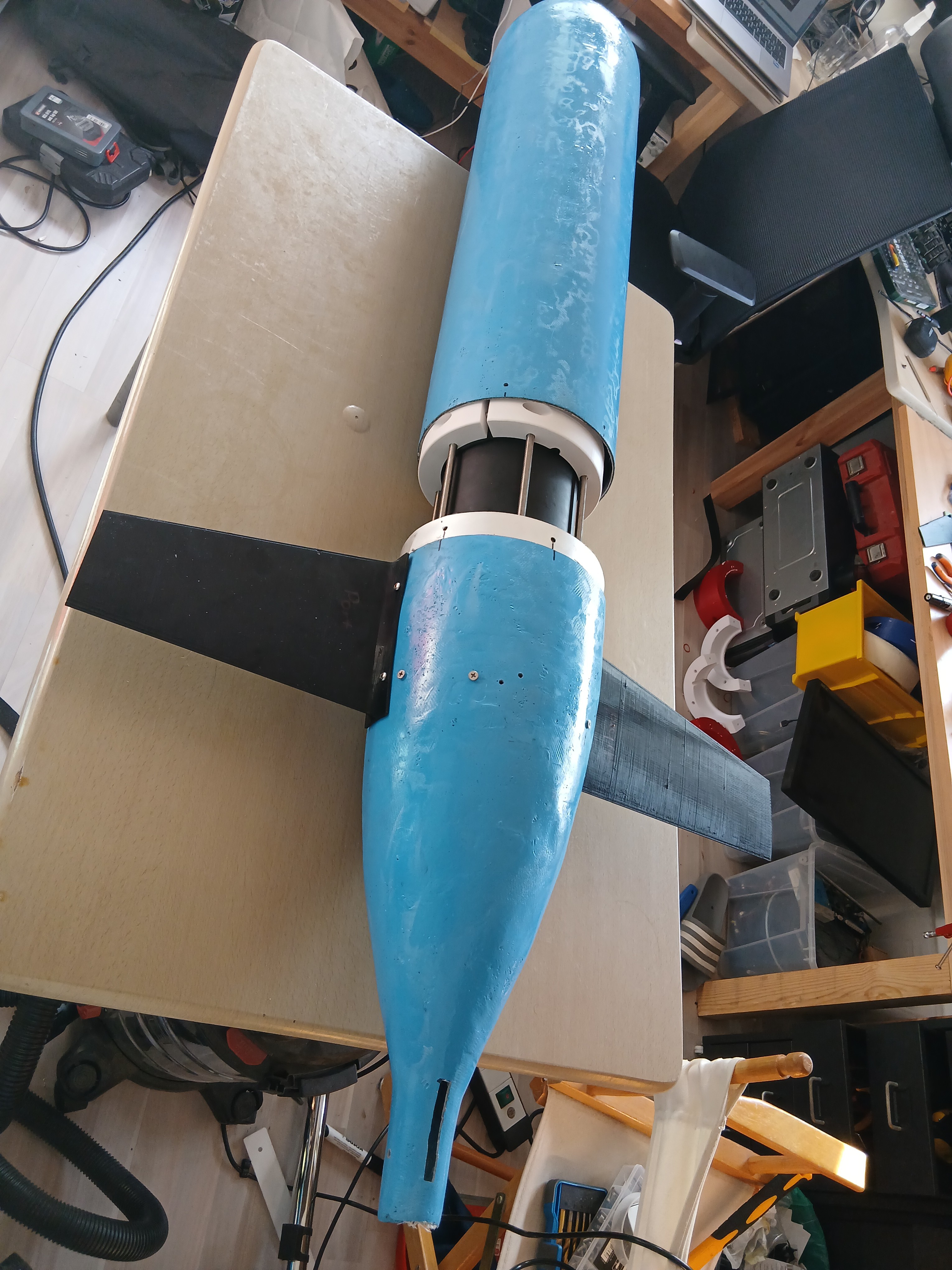
An underwater glider operates on principles similar to those of an aircraft glider, but in water instead of air. Like their airborne counterparts, underwater gliders do not use propellers for propulsion. Instead, they move forward by converting vertical motion into forward glide using their wings.

The key difference lies in how they return upward after descending. Underwater gliders use a clever buoyancy-based mechanism: they are designed to have a density very close to that of the surrounding water. By slightly changing their volume—using systems such as a piston pump or an oil-filled bladder—they can adjust their density. This allows them to alternately become slightly heavier than water (to descend) or slightly lighter (to ascend), effectively “flying” up and down through the water column.

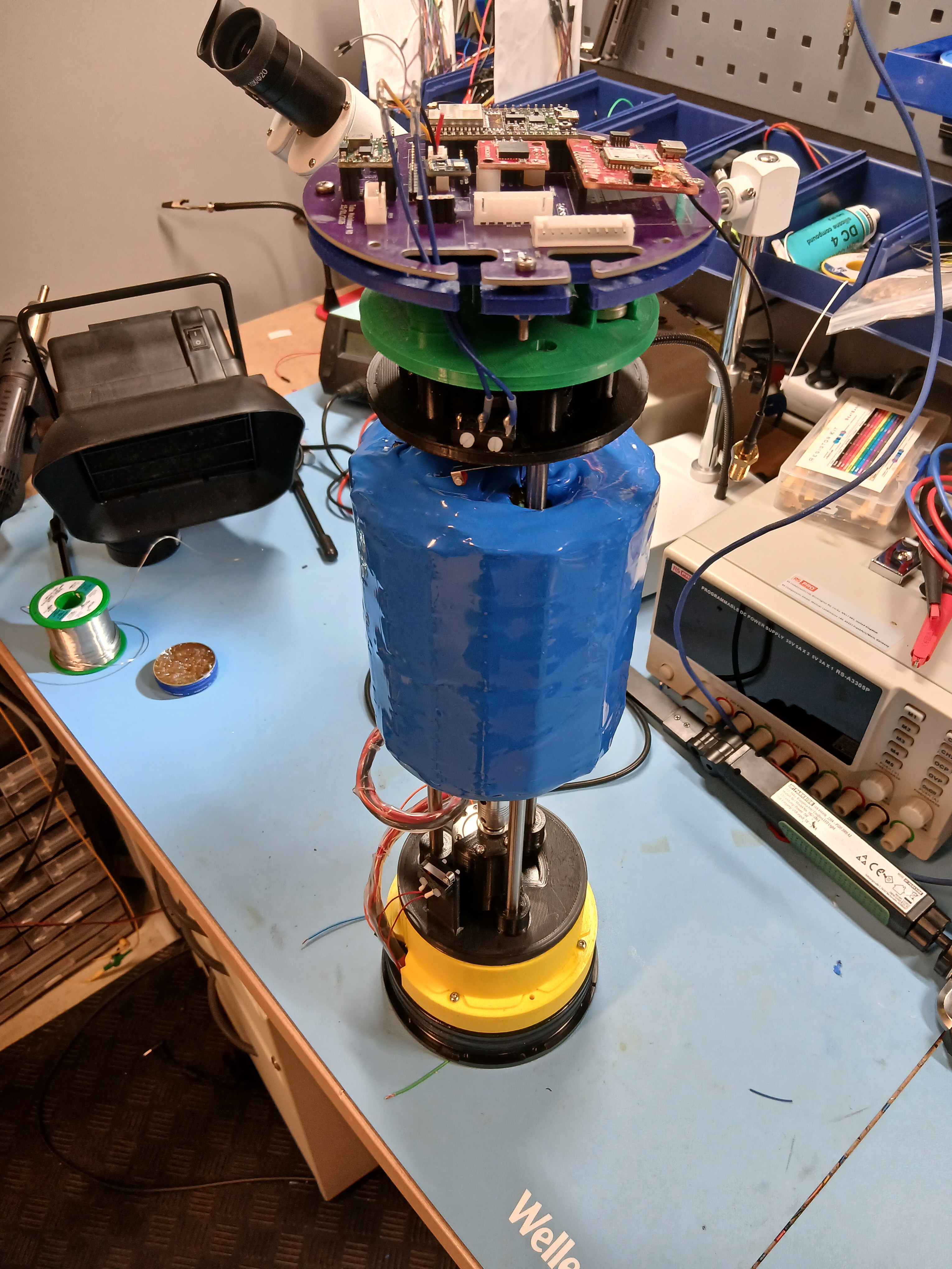
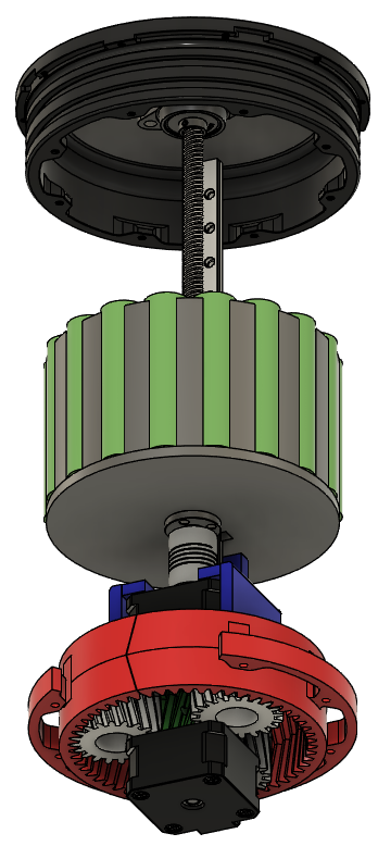
To control their movement, gliders shift an internal mass—typically the battery pack. Moving this mass forward or backward changes the pitch, controlling ascent and descent angles. Rotating the mass laterally induces roll, which in turn allows the glider to steer and maintain a desired heading.

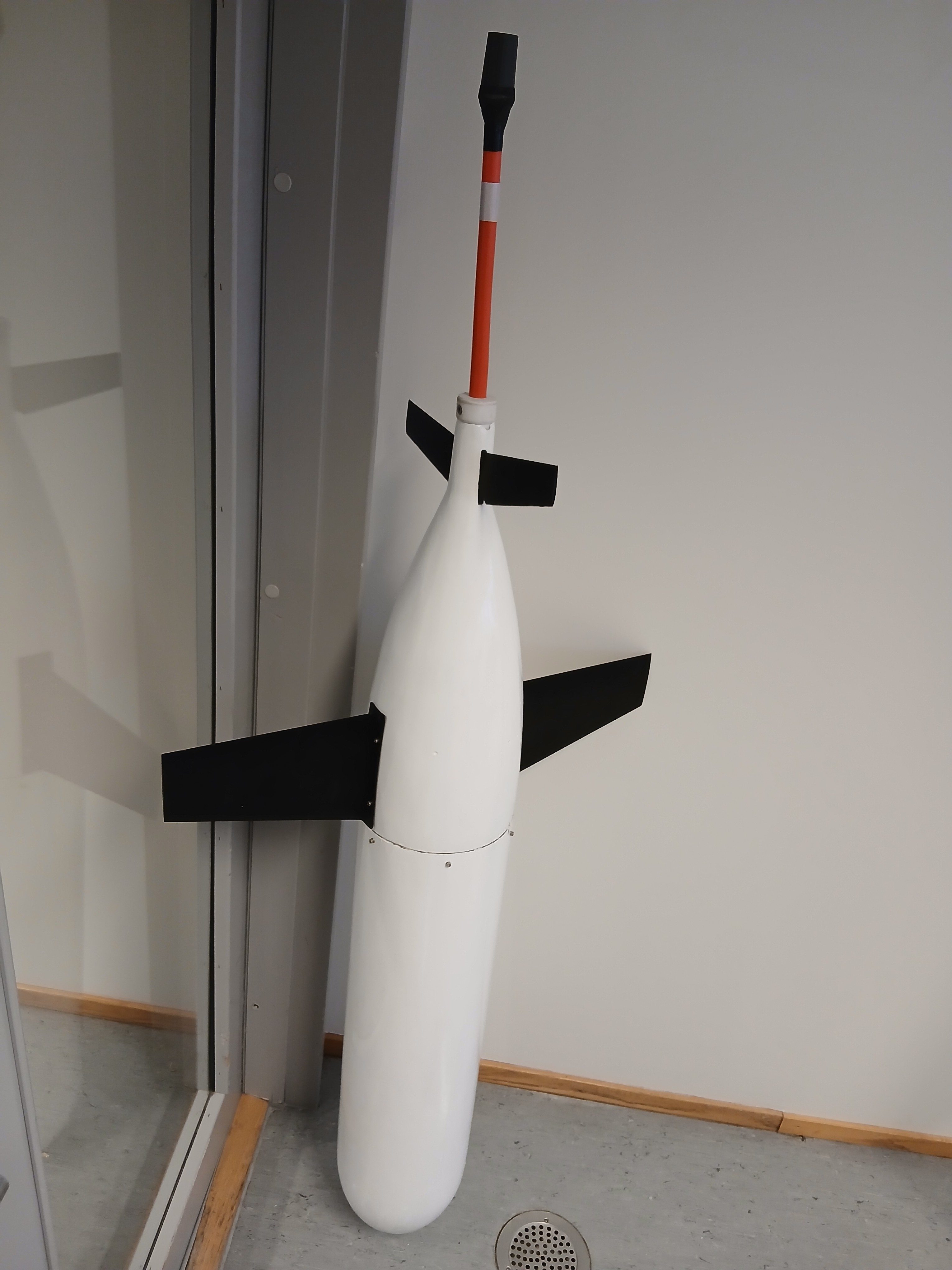
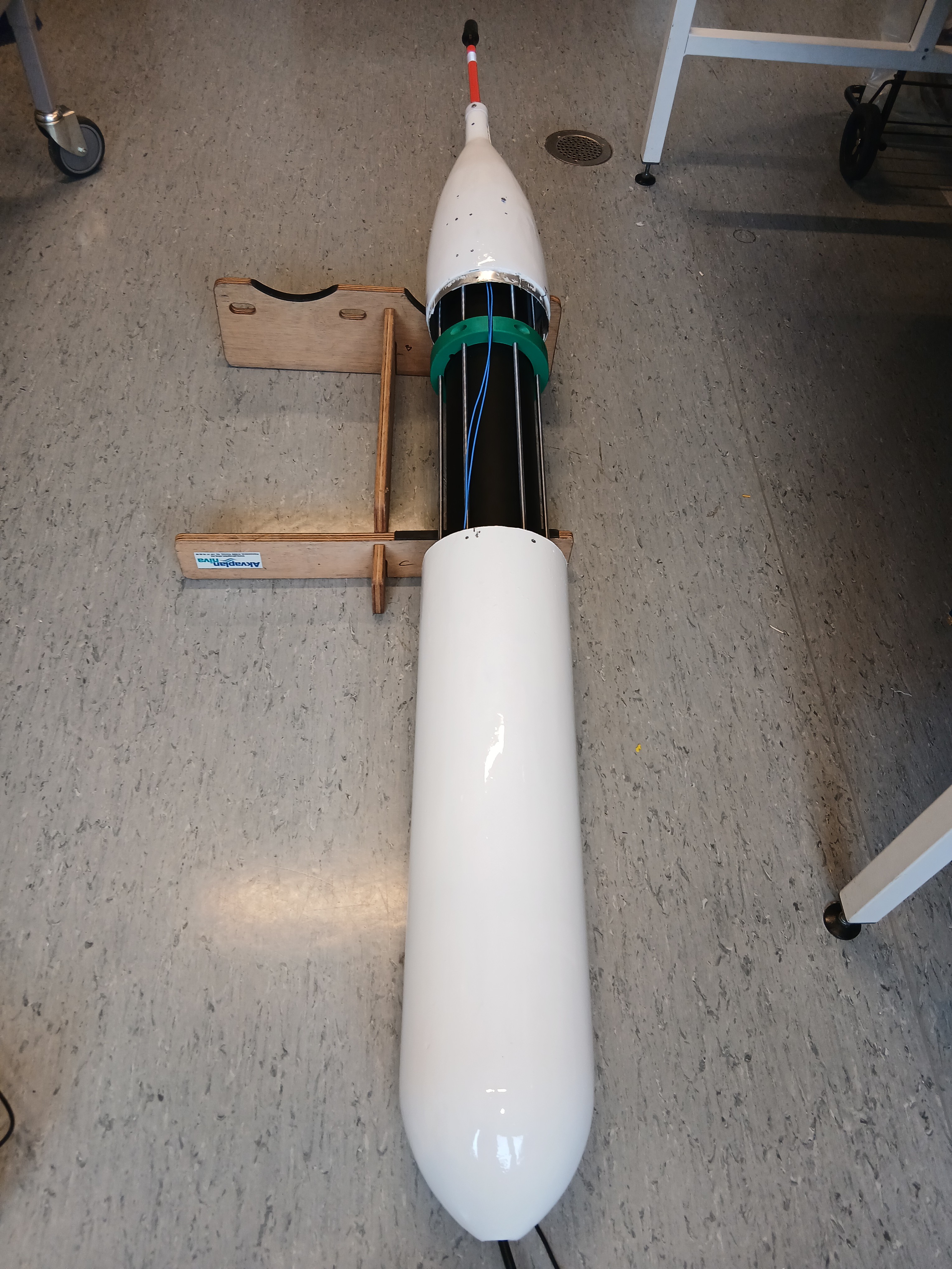
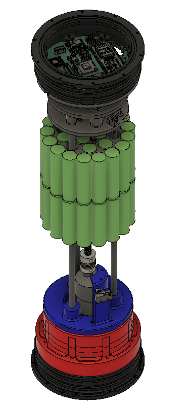
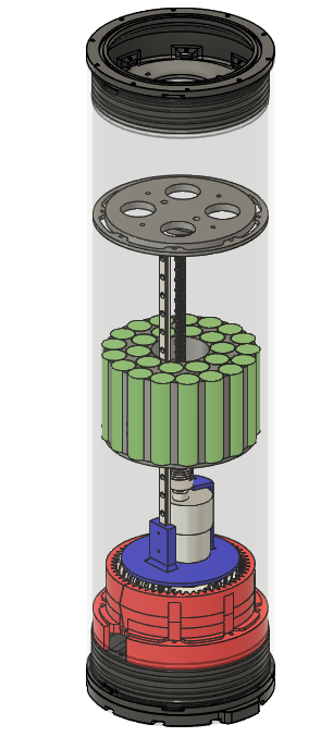
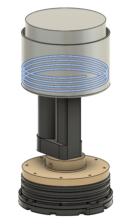
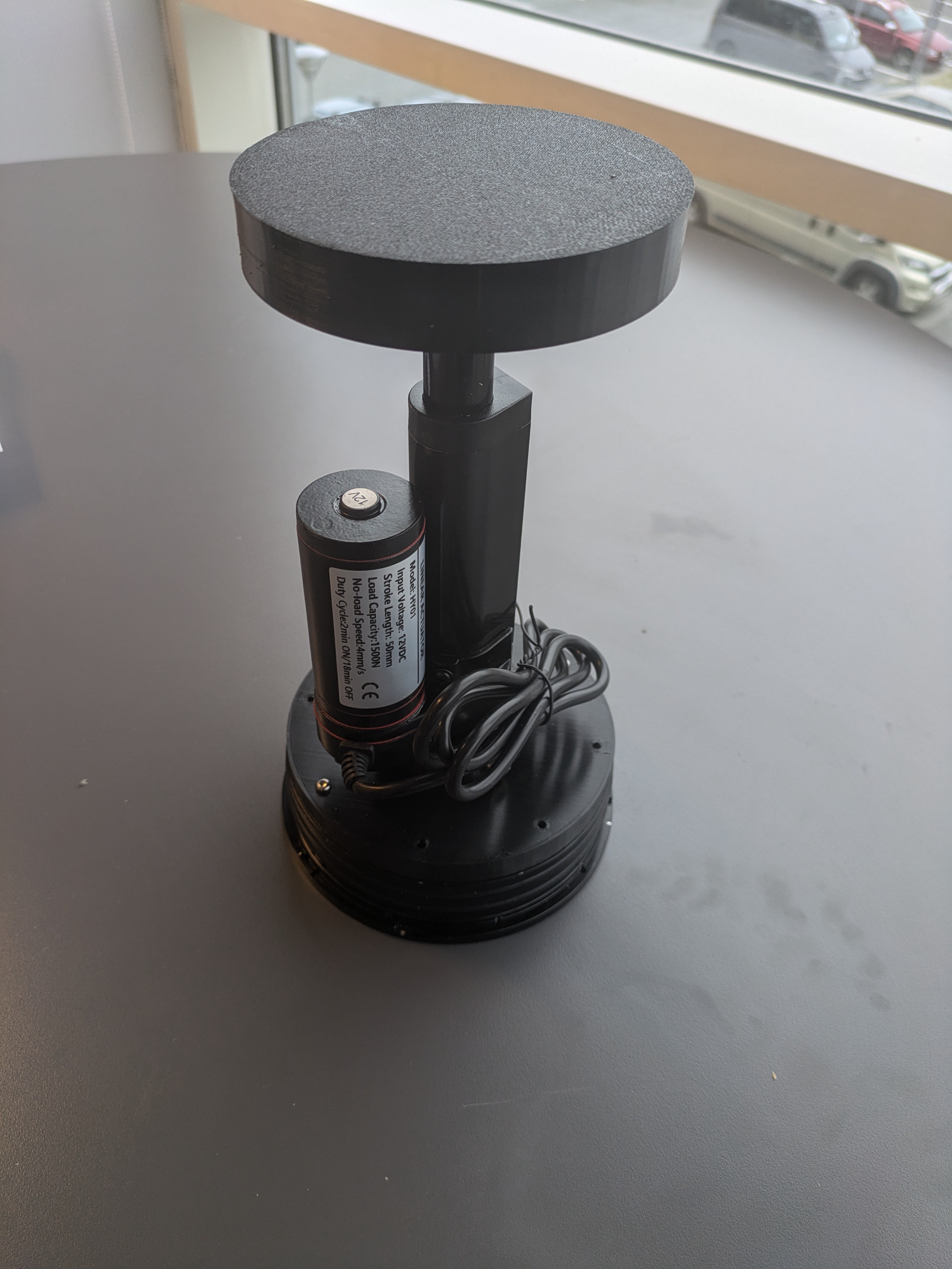
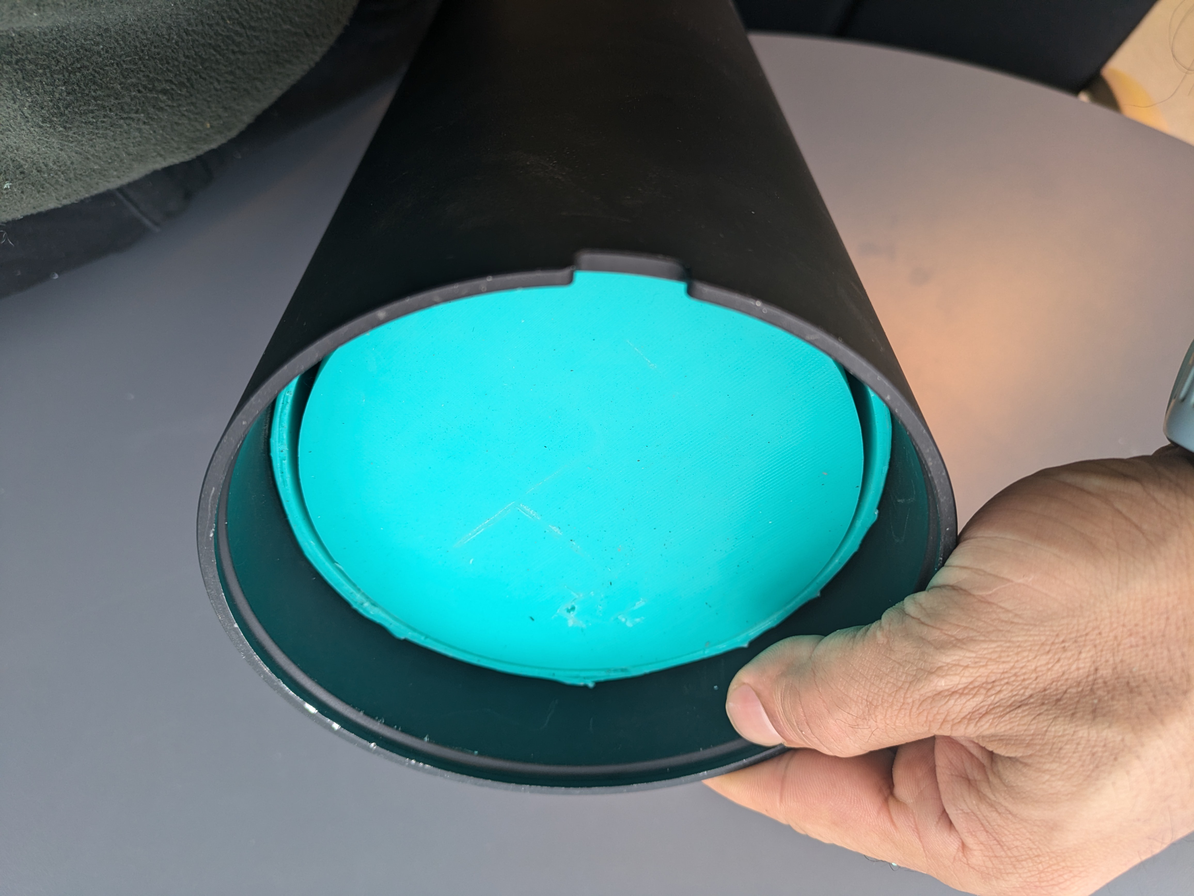
The glider will consist of three separate sections. These are buoyancy drive, mass shifter and electronics sections. Each section will be housed inside a 5" BlueRobotics pressure housing. This way, later we can upgrade the buoancy drive section to reach the full 1000m depth.

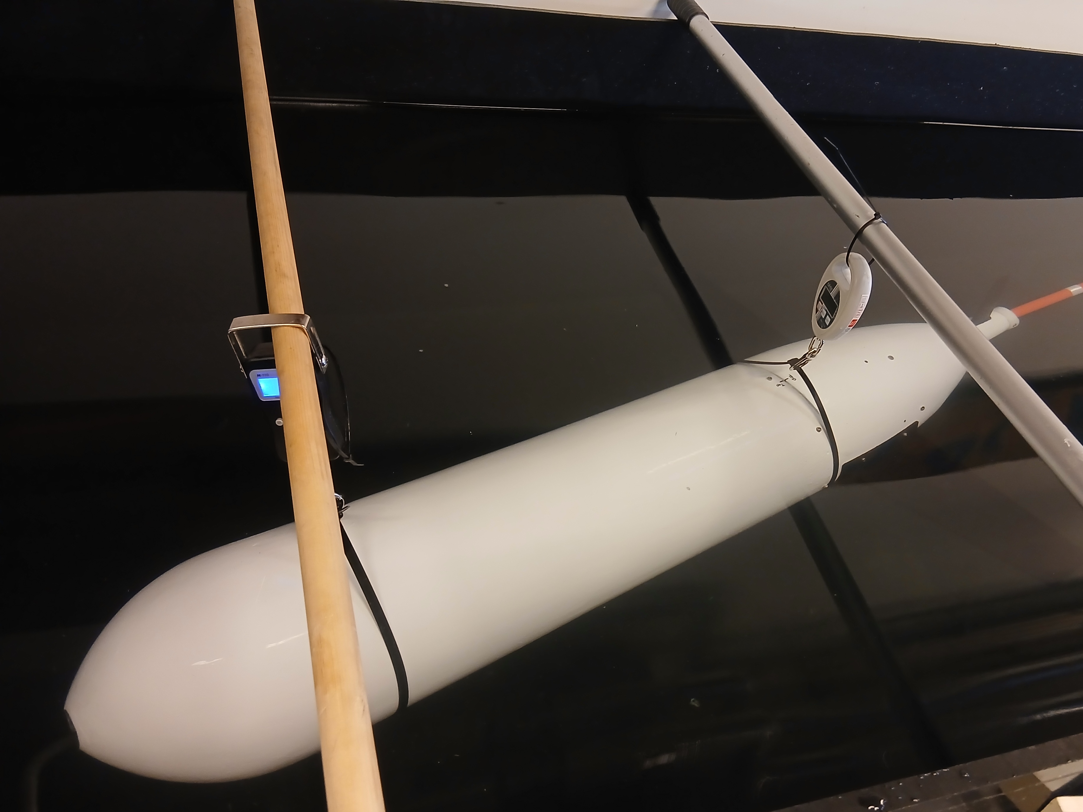
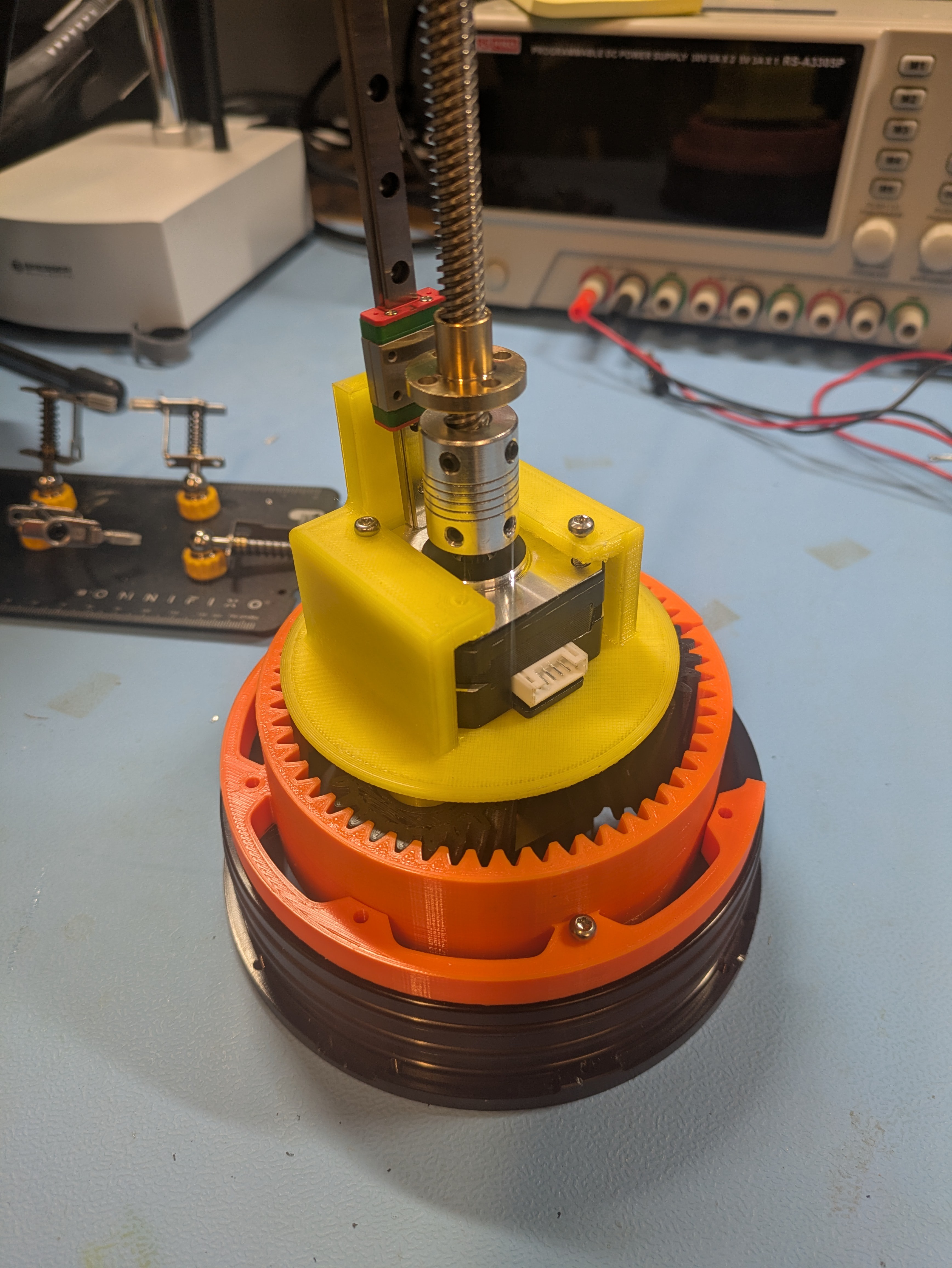
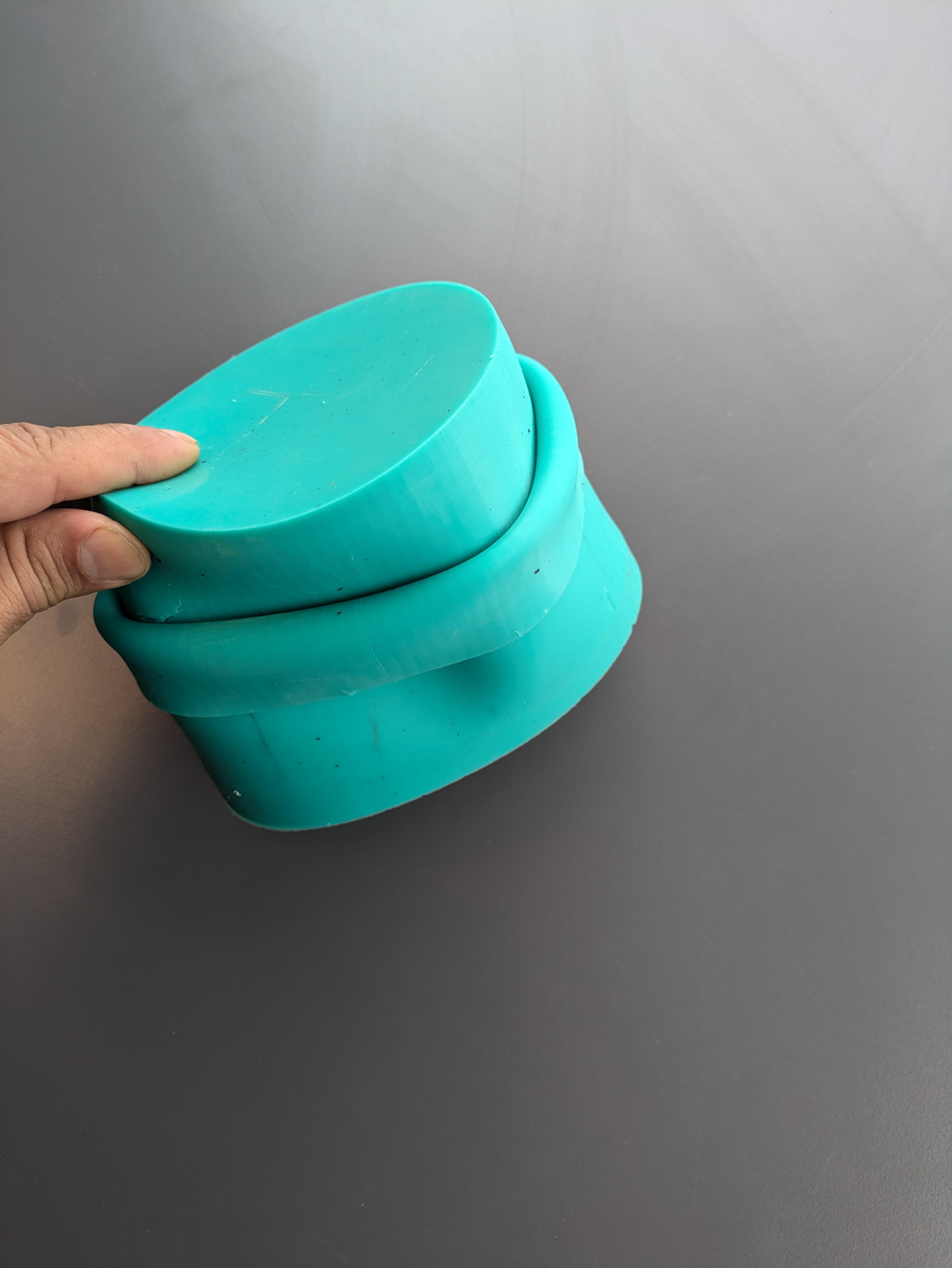
Initially I will focus on making a simple but robust buoyancy drive system. This will inistially consist of a custom-made rolling diaphragm and a linear actoator. Next step is to focus on the mass shifter system. As for comms, I am planning to use GSM and LoRa at the beginning and add Iridium at a later stage. The aim of this first build is to quickly and cheaply put together something functional and see what major changes needs to be done for the next version.

Tuba_step.zip

Full assembly in step

x-zip-compressed - 37.83 MB - 02/18/2026 at 21:15

Download

Tuba.f3d

Full Fusion assembly

fusion - 31.32 MB - 02/18/2026 at 21:14

Download

View all 13 components

  • Ballasting

    Ehsan Abdi4 hours ago 0 comments

    After polishing the fairing a bit, it's now time for ballasting

  • Almost ready for the first test deployment

    Ehsan Abdi02/18/2026 at 20:56 0 comments

    Moving the more detailed week to week logs to Discord. But I will try to post some updates here as well from time to time.

    I did some major changes to the mass shifter assembly 

    and made a proper battery pack for it.

    Added limit switches for pitch as it's the most critical part that really needs them for now but eventually roll, pitch and the pump would all need to have pots to keep track of where they are. 
    Had a friend make fiberglass fairings and we almost went for a deployment, but then decided not to rush it and make some more refinements. 

  • Updates on mass shifter and VBD

    Ehsan Abdi08/11/2025 at 19:14 0 comments

    For the mass shifter, steppers weren't strong enough so switch to geared DC motors. Since these motors are slightly larger, I needed to switch to the 50cm housing instead of the 30cm one.

    It's a quick and dirty design but does the job for now.

    For the buoyancy drive, I played quite a bit with different types of molds for the diaphragm and finally managed to make one in silicon that has no holes. As for the seal, I used this parametric spring tool to make a large snap ring that would push the diaphragm to the housing and create a seal. 

    This together with a little bit of silicon adhesive did the job and I managed to pull a partial vacuum to test for leaks. Then I tested it in water and it does work! Managed to test it down to 5 meters but only have this shot from the initial test.

  • Mass shifter first try

    Ehsan Abdi02/17/2025 at 19:38 0 comments

    I'm still making some slow progress. I'm still experimenting with the design of the mold for the rolling diaphragm seal. I haven't managed to get the result I am looking for just yet. As for the attachment of the seal to the housing, I am now thinking about using some type of snap ring to exert a constant pressure on the walls and create a seal like that. But since I'm waiting for a new order of silicone rubber to arrive up here in the Arctic, I started experimenting with the design of the mass shifter section. I thought it would be easy enough to simply use NEMA steppers for both roll and pitch. I found this cool herringbone planetary gear which would do well for roll mechanism. 

    After printing and putting things together and some testing, it seems llike the NEMA steppers won't have enough torque to do the job, at least not reliably. So I will probably move to geared DC motors and potentiometers.

  • Testing the first design

    Ehsan Abdi08/27/2024 at 21:21 0 comments

    I just printed a couple of parts to quickly try everything together. 

    The hardest part was to glue the seal to the housing. The seal is made of silicon rubber which does not really adhere to anything. But finally, using some silicon-base adhesive I managed to quickly test things together. 

  • Making a Rolling Diaphragm Try#1

    Ehsan Abdi07/11/2024 at 13:46 0 comments

    The idea was to try to make a rolling diaphragm the easiest way I could think of and see what happens. Since it needs to be flexible, I decided to make the first out of silicone rubber. I used the housing itself as part of the mold and 3D printed a few more parts to act as the rest of the mold.

    It didn't turn out too bad but I think I will try another way next time and not using the housing as a part of the mold because I had a really hard time removing the piece!

View all 6 project logs

Enjoy this project?

Share

Discussions

Similar Projects

Does this project spark your interest?

Become a member to follow this project and never miss any updates