-
Final thougts
09/03/2024 at 07:45 • 0 commentsThe contest gets to an end and there is unfortunately no time to make any hardware improvements.
But i think it turned out pretty well. Game is working on two AA batteries and the BOM is quite low.Also its reusable for any future software/game project : )
Lets see what the future holds.Only thing i can improve for a next version would be:
Ditch the power button and make it sleep/wakeup on a button push -> Save 0,56€
Replace the two battery holders with a single one for two batteries -> Save 1,30€
-> New total cost of ~10,74€Maybe add some additional Caps for protection. They cost almost nothing ...
However.
If you decide to use this project as a base: Have fun :D
-
Game logic
09/03/2024 at 07:34 • 0 commentsWe can now show something on the screen. Lets write the game
-> You can find the game logic in the main.c
The game logic itself is pretty much straight forward but with one twist:
For the playing field every LED is numbered (0-63, bottom left = 0, top right =63) and every LED got an signed integer. (so its a 64Byte array)This way the head position of each player is just a number instead of coordinates.
Moving up = position +8, down -8, left -1, right +1Also the reason to use a signed integer:
Positive value = Player 1
Negative value = Player 2
-> Storing both players in one Array saving some data. -
Driving the LED´s
09/03/2024 at 07:26 • 0 commentsThe LED´s are controlled row for row.
Every row is two bytes, one for RED, one for GREEN (= 16Led per row -> 16Bit)
So we have a screen buffer of (2*8Bit)*8Rows = 16BytesDisplaying frame therefore consists of:
1. Combining RED and GREEN buffer of current row to a 16Bit integer
2. Sending the 16Bit via Data pin
3. Pulling LAT HIGH(driver will output last data received)
4. Pull PNP Transostor of corresponding row LOW
5. Wait for a ON-time
6. Pull NPN HIGH
7. Pull LAT LOW
8. Repeat for every rowSince this is happening so fast, the LED´s are in fact blinking, but since our eyes are so "slow" we see it as a constant on.
-
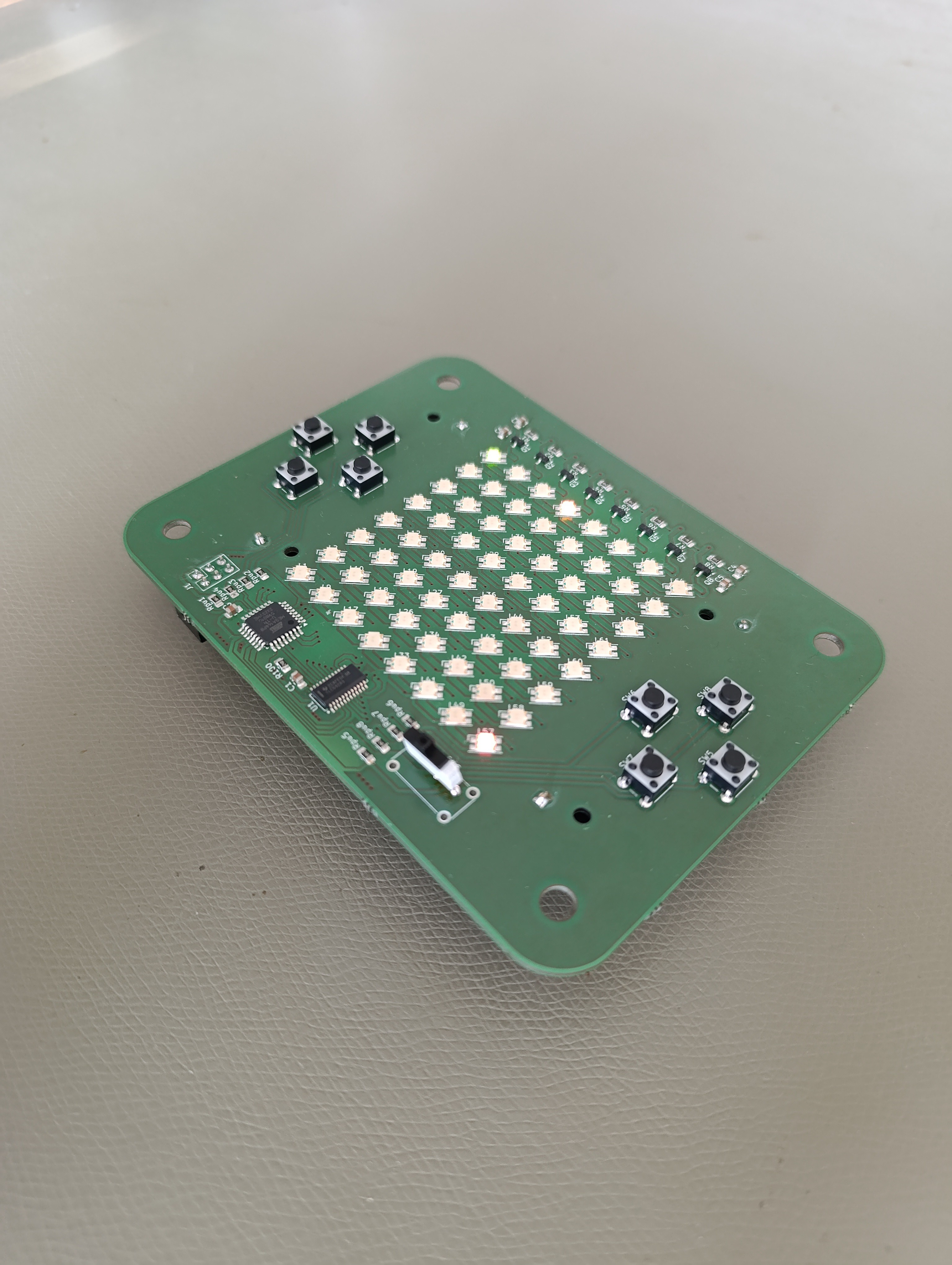
Soldering time
09/03/2024 at 06:39 • 0 commentsWell, *german shipping company* somehow lost my package. But thanks to the incredible guys from Aisler i still got some new PCB´s just in time.

Turned out quite nice. I somehow managed to order the wrong powerswitch so i had to use a substitute.
Lets get programming.
-
First calculation
07/29/2024 at 20:27 • 0 commentsWhile im waiting for the pcb, i ordered the parts on digikey and did my first calculation.
For the other components i did not crunsh the numbers as much. The reason being: im just a lazy bum.
Parts list so far:LED, 64x 0,078€
Atmega168, 1x 1.36€
AA Battery holder, 2x 1.30€
0805 Capacitor, 8x 0.063€
0805 Resistor, 17x 0.034€
PNP BJT, 8x 0.065€
Driver, 1x 0.56€
Pushbutton, 8x 0.115€
Powerswitch, 1x 0.56€= 12.60€
Well a bit over the hoped outcome.
In hindsight there a a few points i could have done better:
I used a AA Battery holder, just using clips or coin cells would cut the cost of them by half or 2/3.
Ditching the Buttons and go for capacitive touch. (I didnt dare to for the contest because i never tried it)
Maybe i can even find a row-driver?
Programming the game will let me see if i can go for a smaller controller.
Heck you could even ditch the powerbutton. Just use the sleep mode and wake him up with a button and ......But first things first, im getting ahead of myself. Lets make get the first version to work....
-
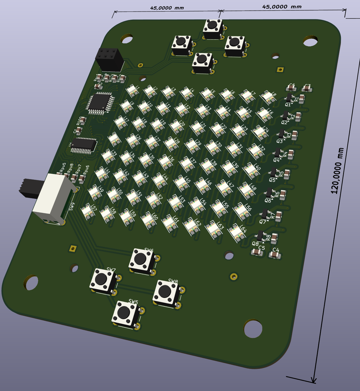
Prototyping time
07/29/2024 at 20:01 • 0 commentsTwo long evenings later, a layout was born and a first prototype ordered.
Well first prototype is nice to say, considering the short time available it will propably be the final version.
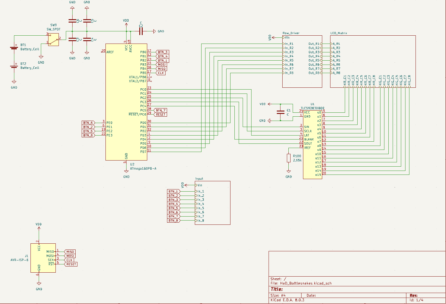
The rest of the circuit is pretty straightforward. WIth the shift register i managed to have only 2 free pins left (besides the programming pins). Also the driver/register has this nice function that it limits the current for us. No need for resistors, some cents saved.
Oscillator? No need, internal is good enough.
Voltage regulator/supervisor? No need, input range of the components is wide enough.
It would be possible to multiplex the inputs too but there is no need here.In hindsight the only critical thing i forgot for now would be a diode for reverse polarity protection.
But that would bring down the already low 3V from the planned AA batteries. Which reminds me that the driver wants a VCC of 3V-5V.
Quite Exciting. The datasheet does not mention any undervoltage lockout. Will it work? Only the first assembly will show. -
How to control those LED´s .....
07/29/2024 at 16:35 • 0 commentsOk so after selecting the type of display i want to use we have one problem.
8 rows + 8 columns red + 8 columns green = 24 pins i need for the controller
Adding 8 buttons brings us to 32 needed IO pins .... too much for the average ATMega i want to use.
Now what?
Enter: Shift registers for LED´s
Now we can control a whole column by a serial interface. But why 16 bit you might ask? Well, we can split the register into 8 red and 8 green. So we can control both colors per row at the same time in one go.
Also we can ditch 16 transistors. Looking at the cheapest i found at this time we effectively even save half a euro (1,04€ for 16 Transistors VS 0,56€ for 1 driver)
-
First Ideas
07/29/2024 at 16:15 • 0 commentsFirst thought is obviously on what to use as a display. Modules are first too expensive and second against my own rule.
So whats left ... 7 segment display? The LED´s look like snakes so it might be a fun idea. But no.
Since i want to make it a two player game, i might want to add some color to distinguish between the players. So RGB LED´s it is. But there are two problems. Affordable ones are in crazy small packages, and programmable ones are too expensive.
Enter: Dual Color LED´s.
They might not be as fancy, but do the job for a bit lower price. Also with the added advantage of having one pin less which will be useful later.
For size i settled for a classic 8x8 matrix. Increasing the playfield just increases the cost exponentially and this feels OK.
Maybe something for another project.
Project Battlesnakes
A classic game of snake, but with a twist and added hardware constraints.