 kutluhan_aktar
-
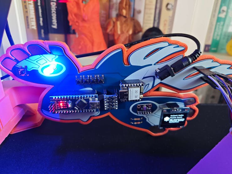
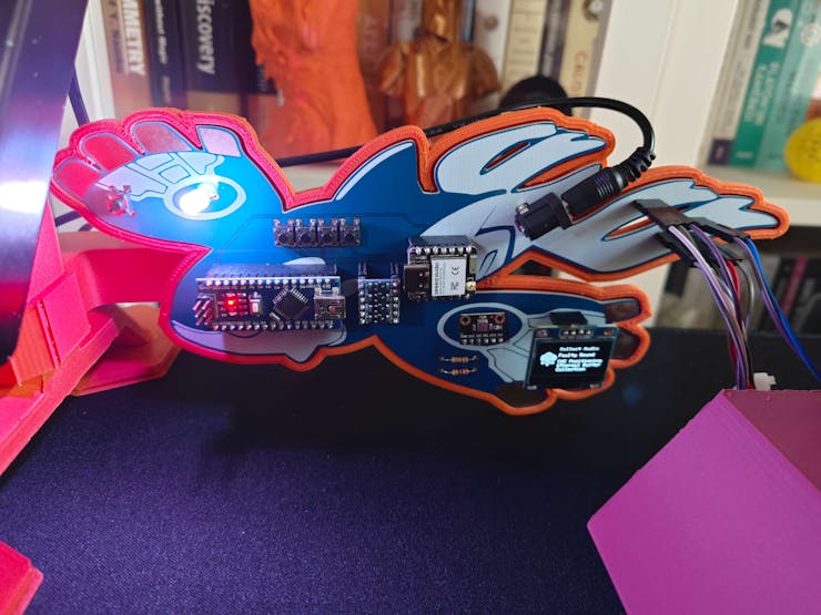
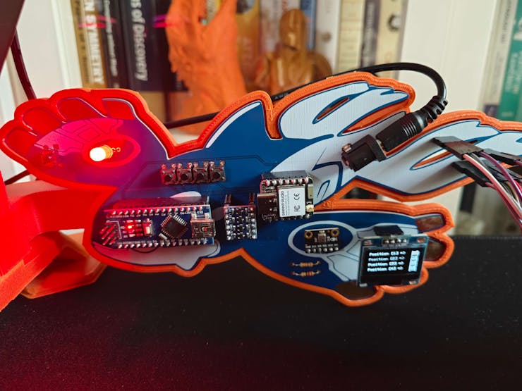
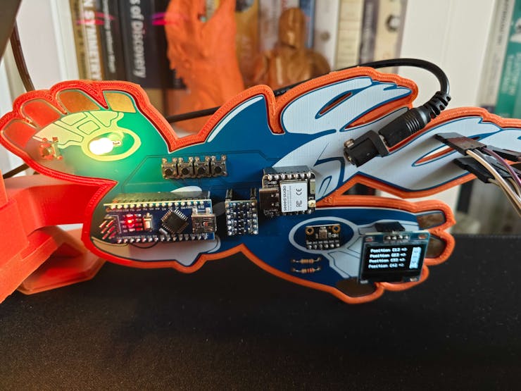
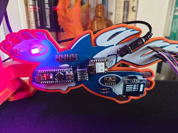
21Step 6.c: Displaying images on the SSD1306 OLED screen and the ST7735 TFT display
I followed the exact same process to display images on the SSD1306 OLED screen (XIAO ESP32C6) and the ST7735 TFT display (Photon 2).
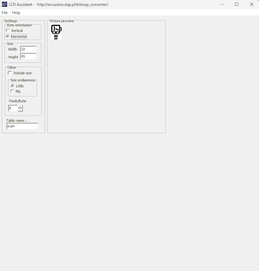
#️⃣ To be able to display images (icons), first convert image files (PNG or JPG) to monochromatic bitmaps. Then, convert the generated bitmaps to compatible C data arrays. I decided to utilize LCD Assistant to create C data arrays.
#️⃣ After installing LCD Assistant, upload a monochromatic bitmap and select Vertical or Horizontal, depending on the screen type.
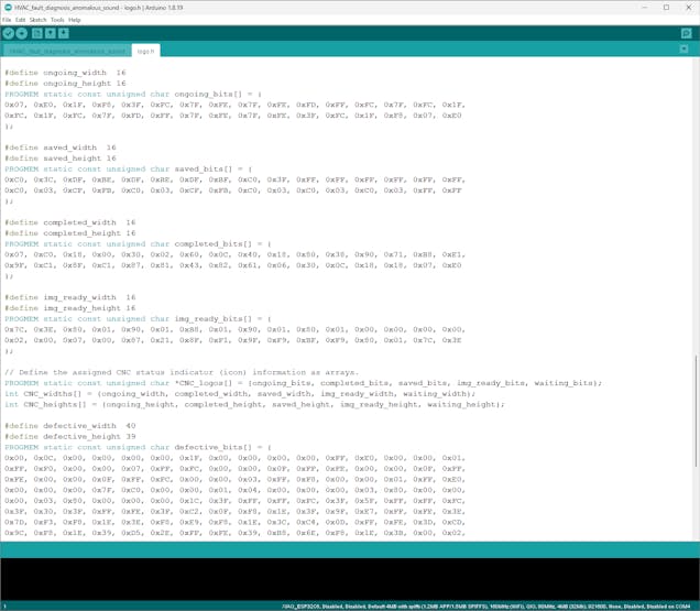
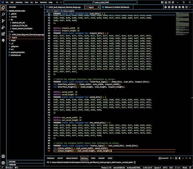
#️⃣ Then, save all the converted C data arrays to the logo.h file.
⭐ In the logo.h file, I defined multi-dimensional arrays to group the assigned logos and their sizes — width and height.
// XIAO ESP32C6 ://// Define the assigned interface logo information as arrays.PROGMEM static const unsigned char *interface_logos[] = {home_bits, audio_bits, faulty_audio_bits, cnc_pos_bits};int interface_widths[] = {home_width, audio_width, faulty_audio_width, cnc_pos_width};int interface_heights[] = {home_height, audio_height, faulty_audio_height, cnc_pos_height};//display.drawBitmap(0, (SCREEN_HEIGHT-l_h)/2, interface_logos[menu_option], l_w, l_h, SSD1306_WHITE);&&&// Particle Photon 2 : //// Define the assigned interface logo information as arrays.PROGMEM static const unsigned char *interface_logos[] = {home_bits, scan_bits, inspect_bits};int interface_widths[] = {home_width, scan_width, inspect_width};int interface_heights[] = {home_height, scan_height, inspect_height};//st7735.drawBitmap((SCREEN_WIDTH-interface_widths[i_x])/2, (SCREEN_HEIGHT-interface_heights[i_x])/2, interface_logos[i_x], interface_widths[i_x], interface_heights[i_x], _menu.scan_c);![]()
![]()
![]()
-
22Step 7: Collecting the raw audio buffers produced by the I2S MEMS microphone
After setting up all development boards on their associated software, I started to work on improving and refining code to perform functions flawlessly. First, I focused on programming XIAO ESP32C6, which manages audio sample collection and data transmission to the web application.
As explained in the previous steps, the device performs lots of interconnected features between different development boards and the web application for data collection and running advanced AI models. Thus, the described code snippets show the different aspects of the same code file. Please refer to the code files or the demonstration videos to inspect all interconnected functions in detail.
📁 HVAC_fault_diagnosis_anomalous_sound.ino
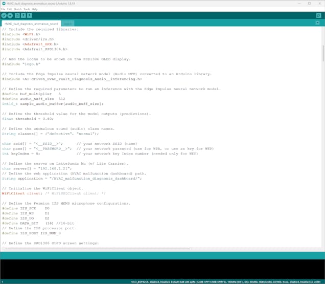
⭐ Include the required libraries.
#include <WiFi.h>#include <driver/i2s.h>#include <Adafruit_GFX.h>#include <Adafruit_SSD1306.h>
⭐ Add the icons to be shown on the SSD1306 OLED display, which are saved and grouped in the logo.h file.
#include "logo.h"
⭐ Define the required server configurations for the web application hosted on LattePanda Mu.
⭐ Then, initialize the WiFiClient object.
char server[] = "192.168.1.21";// Define the web application (HVAC malfunction dashboard) path.String application = "/HVAC_malfunction_diagnosis_dashboard/";// Initialize the WiFiClient object.WiFiClient client; /* WiFiSSLClient client; */
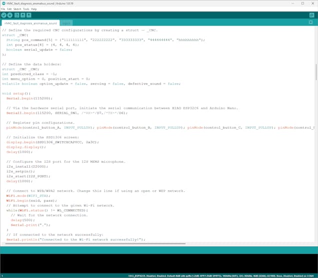
⭐ Define the Fermion I2S MEMS microphone pin configurations, audio sample bits, and the I2S processor port.
#define I2S_SCK D0#define I2S_WS D1#define I2S_DO D2#define DATA_BIT (16) //16-bit// Define the I2S processor port.#define I2S_PORT I2S_NUM_0
⭐ Configure the SSD1306 screen settings.
#define SCREEN_WIDTH 128 // OLED display width, in pixels#define SCREEN_HEIGHT 64 // OLED display height, in pixels#define OLED_RESET -1 // Reset pin # (or -1 if sharing Arduino reset pin)Adafruit_SSD1306 display(SCREEN_WIDTH, SCREEN_HEIGHT, &Wire, OLED_RESET);
⭐ In the i2s_install function, configure the I2S processor port with the passed sampling rate and set the channel format as ONLY_RIGHT.
void i2s_install(uint32_t sampling_rate){ // Configure the I2S processor port for the I2S microphone (ONLY_RIGHT). const i2s_config_t i2s_config = { .mode = i2s_mode_t(I2S_MODE_MASTER | I2S_MODE_RX), .sample_rate = sampling_rate, .bits_per_sample = (i2s_bits_per_sample_t)DATA_BIT, .channel_format = I2S_CHANNEL_FMT_ONLY_RIGHT, .communication_format = i2s_comm_format_t(I2S_COMM_FORMAT_STAND_I2S), .intr_alloc_flags = 0, .dma_buf_count = 16, .dma_buf_len = audio_buff_size, .use_apll = false }; i2s_driver_install(I2S_PORT, &i2s_config, 0, NULL);}⭐ In the i2s_setpin function, assign the given I2S microphone pin configurations to the defined I2S port via the built-in I2S driver.
void i2s_setpin(){ // Set the I2S microphone pin configurations. const i2s_pin_config_t pin_config = { .bck_io_num = I2S_SCK, .ws_io_num = I2S_WS, .data_out_num = -1, .data_in_num = I2S_DO }; i2s_set_pin(I2S_PORT, &pin_config);}⭐ Wait until XIAO ESP32C6 establishes a successful connection with the given Wi-Fi network.
WiFi.mode(WIFI_STA); WiFi.begin(ssid, pass); // Attempt to connect to the given Wi-Fi network. while(WiFi.status() != WL_CONNECTED){ // Wait for the network connection. delay(500); Serial.print("."); } // If connected to the network successfully: Serial.println("Connected to the Wi-Fi network successfully!");⭐ According to the pressed control button (A or C), adjust the highlighted menu option number by one — -1 (UP) or +1 (DOWN).
if(!digitalRead(control_button_A)){ menu_option-=1; if(menu_option < 0) menu_option = 3; delay(500); } if(!digitalRead(control_button_C)){ menu_option+=1; if(menu_option > 3) menu_option = 0; delay(500); }⭐ In the show_interface function:
⭐ According to the passed screen command and menu option number, get the assigned icon information, show the home screen with the highlighted menu option, or display the associated layout after the highlighted menu option is selected.
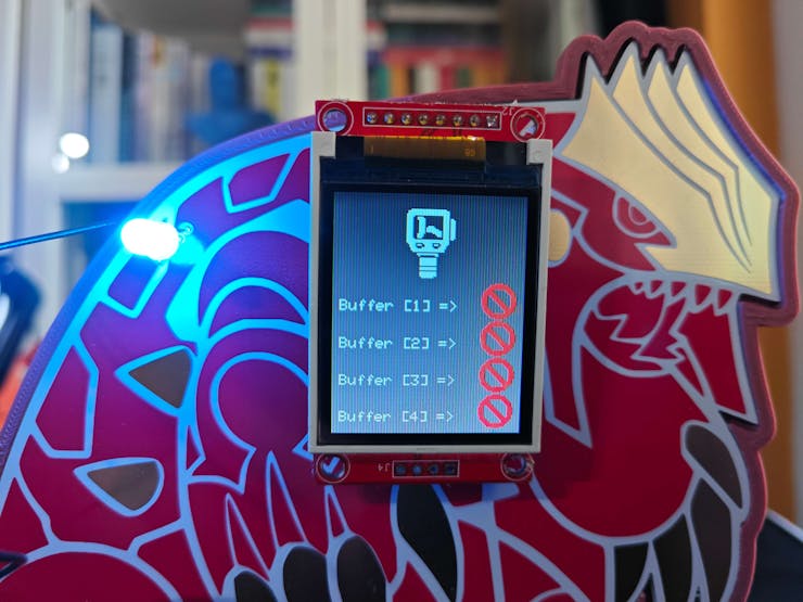
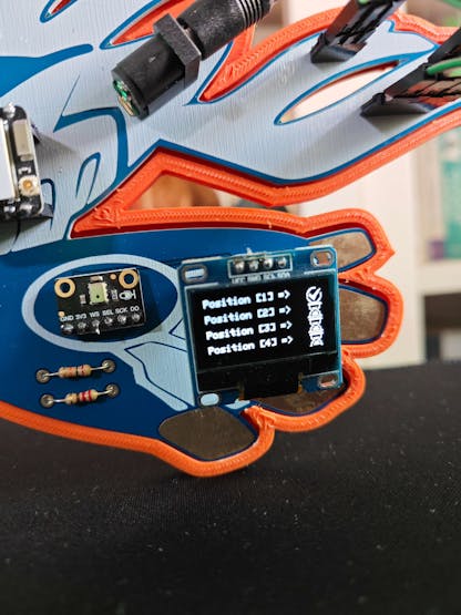
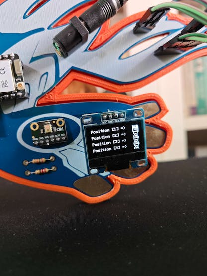
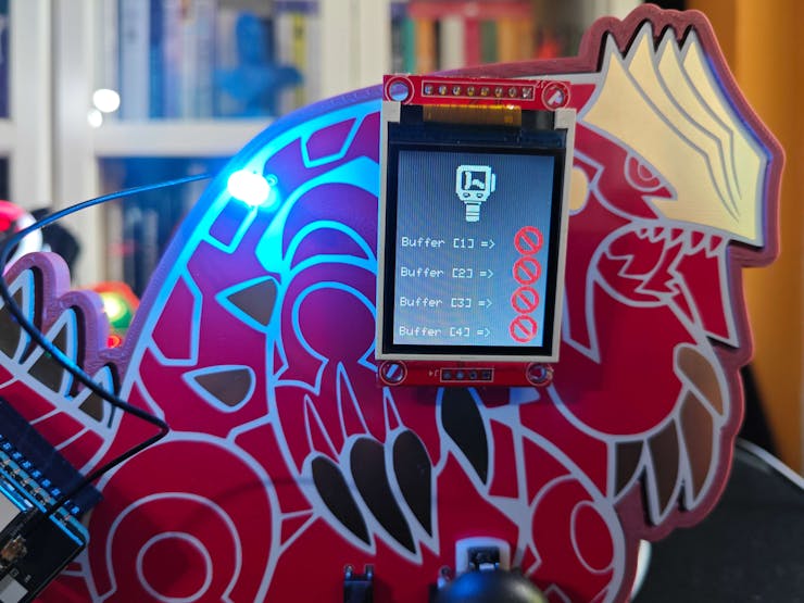
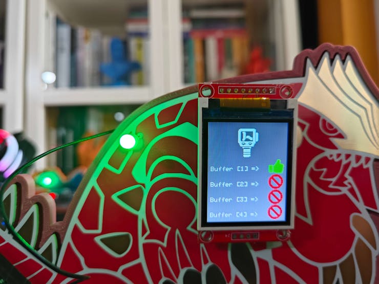
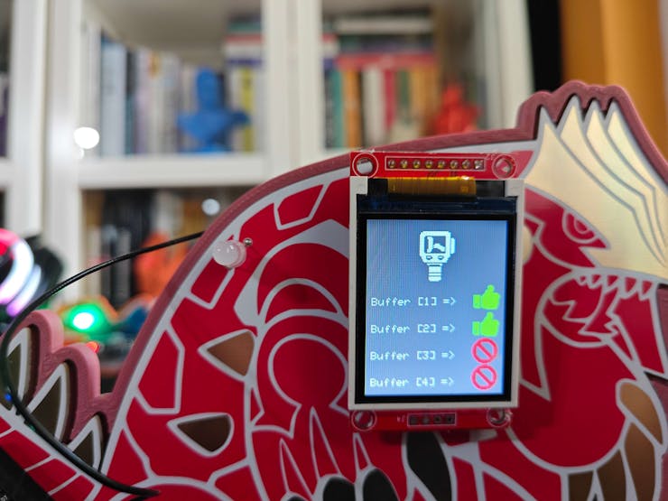
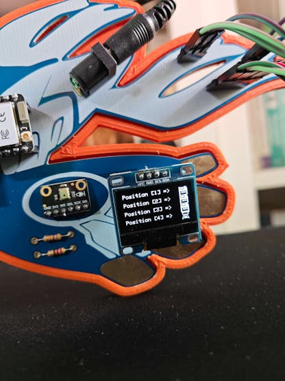
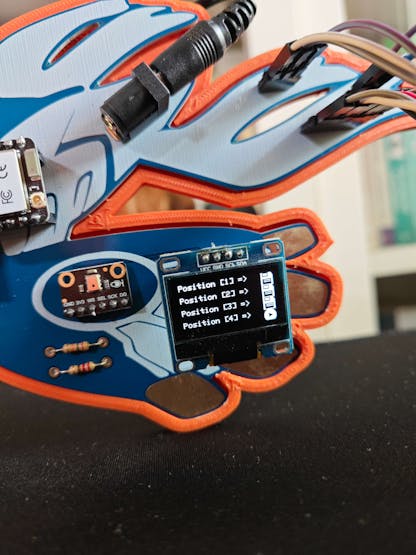
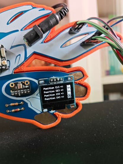
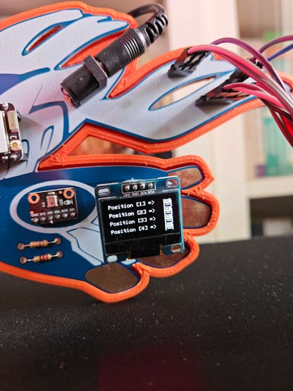
⭐ Depending on the status of the CNC positioning process (Waiting, Ongoing, Saved, or Image Ready), display the associated buffer operation status indicator on the screen for each positioning point (location).
⭐ Show the associated class icon and name according to the audio class predicted by the Audio MFE model.
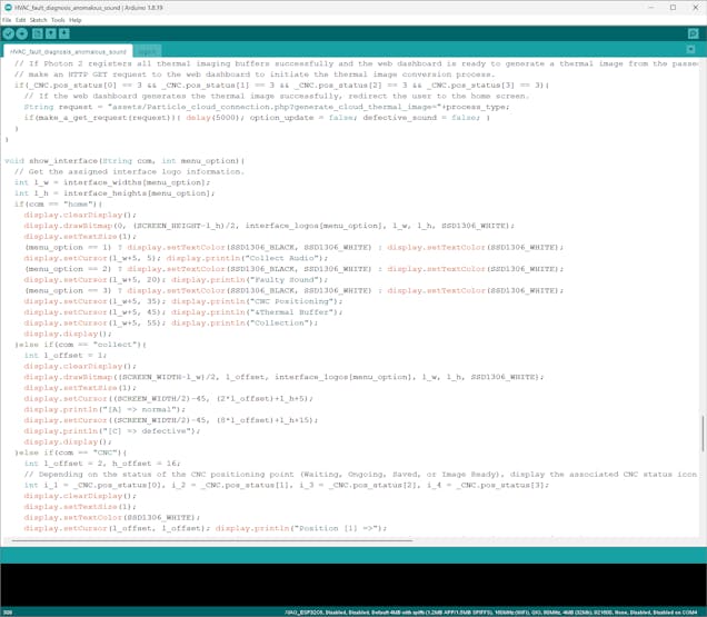
void show_interface(String com, int menu_option){ // Get the assigned interface logo information. int l_w = interface_widths[menu_option]; int l_h = interface_heights[menu_option]; if(com == "home"){ display.clearDisplay(); display.drawBitmap(0, (SCREEN_HEIGHT-l_h)/2, interface_logos[menu_option], l_w, l_h, SSD1306_WHITE); display.setTextSize(1); (menu_option == 1) ? display.setTextColor(SSD1306_BLACK, SSD1306_WHITE) : display.setTextColor(SSD1306_WHITE); display.setCursor(l_w+5, 5); display.println("Collect Audio"); (menu_option == 2) ? display.setTextColor(SSD1306_BLACK, SSD1306_WHITE) : display.setTextColor(SSD1306_WHITE); display.setCursor(l_w+5, 20); display.println("Faulty Sound"); (menu_option == 3) ? display.setTextColor(SSD1306_BLACK, SSD1306_WHITE) : display.setTextColor(SSD1306_WHITE); display.setCursor(l_w+5, 35); display.println("CNC Positioning"); display.setCursor(l_w+5, 45); display.println("&Thermal Buffer"); display.setCursor(l_w+5, 55); display.println("Collection"); display.display(); }else if(com == "collect"){ int l_offset = 1; display.clearDisplay(); display.drawBitmap((SCREEN_WIDTH-l_w)/2, l_offset, interface_logos[menu_option], l_w, l_h, SSD1306_WHITE); display.setTextSize(1); display.setCursor((SCREEN_WIDTH/2)-45, (2*l_offset)+l_h+5); display.println("[A] => normal"); display.setCursor((SCREEN_WIDTH/2)-45, (8*l_offset)+l_h+15); display.println("[C] => defective"); display.display(); }else if(com == "CNC"){ int l_offset = 2, h_offset = 16; // Depending on the status of the CNC positioning point (Waiting, Ongoing, Saved, or Image Ready), display the associated CNC status icon on the screen. int i_1 = _CNC.pos_status[0], i_2 = _CNC.pos_status[1], i_3 = _CNC.pos_status[2], i_4 = _CNC.pos_status[3]; display.clearDisplay(); display.setTextSize(1); display.setTextColor(SSD1306_WHITE); display.setCursor(l_offset, l_offset); display.println("Position [1] =>"); display.drawBitmap(SCREEN_WIDTH-CNC_widths[i_1]-l_offset, l_offset, CNC_logos[i_1], CNC_widths[i_1], CNC_heights[i_1], SSD1306_WHITE); display.setCursor(l_offset, l_offset + h_offset); display.println("Position [2] =>"); display.drawBitmap(SCREEN_WIDTH-CNC_widths[i_2]-l_offset, l_offset+h_offset, CNC_logos[i_2], CNC_widths[i_2], CNC_heights[i_2], SSD1306_WHITE); display.setCursor(l_offset, l_offset + (2*h_offset)); display.println("Position [3] =>"); display.drawBitmap(SCREEN_WIDTH-CNC_widths[i_3]-l_offset, l_offset+(2*h_offset), CNC_logos[i_3], CNC_widths[i_3], CNC_heights[i_3], SSD1306_WHITE); display.setCursor(l_offset, l_offset + (3*h_offset)); display.println("Position [4] =>"); display.drawBitmap(SCREEN_WIDTH-CNC_widths[i_4]-l_offset, l_offset+(3*h_offset), CNC_logos[i_4], CNC_widths[i_4], CNC_heights[i_4], SSD1306_WHITE); display.display(); }else if(com == "run"){ int l_c_w = class_widths[predicted_class], l_c_h = class_heights[predicted_class], l_offset = 2; String p_c = "[ "+classes[predicted_class]+" ]"; p_c.toUpperCase(); int p_c_l = p_c.length()*5; display.clearDisplay(); display.drawBitmap((SCREEN_WIDTH-l_c_w)/2, l_offset, class_logos[predicted_class], l_c_w, l_c_h, SSD1306_WHITE); display.setTextSize(1); display.setTextColor(SSD1306_WHITE); display.setCursor((SCREEN_WIDTH-p_c_l)/2, SCREEN_HEIGHT-(6*l_offset)); display.println(p_c); display.display(); }}⭐ In the microphone_sample function:
⭐ Obtain the information generated by the I2S microphone and save it to the input buffer — sample_audio_buffer.
⭐ If the I2S microphone generates raw audio data successfully, scale the produced raw audio buffer depending on the model requirements. Otherwise, the sound might be too quiet for classification.
⭐ If requested for debugging, display the average (mean) output values on the serial plotter.
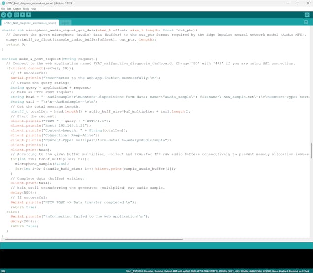
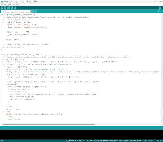
bool microphone_sample(bool _debug){ // Obtain the information generated by the I2S microphone and save it to the input buffer — sample_audio_buffer. size_t bytesIn = 0; esp_err_t result = i2s_read(I2S_PORT, &sample_audio_buffer, audio_buff_size, &bytesIn, portMAX_DELAY); // If the I2S microphone generates raw audio data successfully: if(result == ESP_OK){ Serial.println("\nAudio Data Generated Successfully!"); // Depending on the given model, scale (resize) the raw audio buffer (data) collected by the I2S microphone. Otherwise, the sound might be too quiet for classification. for(int x = 0; x < bytesIn/2; x++){ sample_audio_buffer[x] = (int16_t)(sample_audio_buffer[x]) * 8; } // If requested, display the average (mean) audio data reading on the serial plotter. if(_debug){ int16_t samples_read = bytesIn / 8; if(samples_read > 0){ float mean = 0; for(int16_t i = 0; i < samples_read; ++i){ mean += (sample_audio_buffer[i]); } mean /= samples_read; Serial.println(mean); } } // Exit. return true; }else{ Serial.println("\nAudio Data Collection Failed!"); // Exit. return false; }}⭐ In the make_a_post_request function:
⭐ Connect to the web application with the configured server settings.
⭐ Create the query string by appending the passed URL query (GET) parameters.
⭐ Define the AudioSample boundary parameter to transfer the produced raw audio sample to the web application as a plain text file.
⭐ Estimate the total message (content) length.
⭐ Initiate an HTTP POST request with the created query string as additional URL parameters to the web application.
⭐ While making the POST request, according to the defined buffer multiplier, collect and write (transfer) raw audio buffers consecutively to prevent memory allocation issues.
⭐ Then, conclude data (buffer) writing and the POST request.
⭐ Wait until fully transferring the raw audio sample produced from individual buffers.
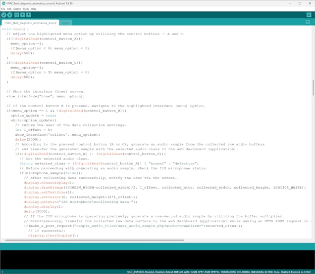
boolean make_a_post_request(String request){ // Connect to the web application named HVAC_malfunction_diagnosis_dashboard. Change '80' with '443' if you are using SSL connection. if(client.connect(server, 80)){ // If successful: Serial.println("\nConnected to the web application successfully!\n"); // Create the query string: String query = application + request; // Make an HTTP POST request: String head = "--AudioSample\r\nContent-Disposition: form-data; name=\"audio_sample\"; filename=\"new_sample.txt\";\r\nContent-Type: text/plain;\r\n\r\n"; String tail = "\r\n--AudioSample--\r\n"; // Get the total message length. uint32_t totalLen = head.length() + audio_buff_size*buf_multiplier + tail.length(); // Start the request: client.println("POST " + query + " HTTP/1.1"); client.println("Host: 192.168.1.21"); client.println("Content-Length: " + String(totalLen)); client.println("Connection: Keep-Alive"); client.println("Content-Type: multipart/form-data; boundary=AudioSample"); client.println(); client.print(head); // According to the given buffer multiplier, collect and transfer I2S raw audio buffers consecutively to prevent memory allocation issues. for(int t=0; t<buf_multiplier; t++){ microphone_sample(false); for(int i=0; i<audio_buff_size; i++) client.print(sample_audio_buffer[i]); } // Complete data (buffer) writing. client.print(tail); // Wait until transferring the generated (multiplied) raw audio sample. delay(5000); // If successful: Serial.println("HTTP POST => Data transfer completed!\n"); return true; }else{ Serial.println("\nConnection failed to the web application!\n"); delay(2000); return false; }}⭐ After highlighting a menu option on the home screen, if the control button B is pressed, navigate to the selected option's layout.
⭐ If the first option (Collect Audio) is activated:
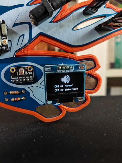
⭐ Inform the user of the audio sample collection settings on the SSD1306 screen.
⭐ According to the pressed control button (A or C), select an audio class for the sample.
- A ➜ normal
- C ➜ defective
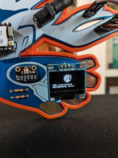
⭐ Before producing an audio sample, check the I2S microphone status by running the microphone_sample function once.
⭐ If the I2S microphone generates a raw audio buffer as expected, notify the user on the screen.
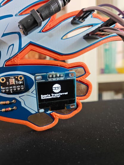
⭐ Then, collect raw audio buffers and transfer them simultaneously to the web application until reaching the predefined buffer multiplier number in order to send the produced audio sample without triggering memory allocation errors.
⭐ Notify the user of the web application data transmission success on the screen by showing the associated status icons.
⭐ If the control button D is pressed, redirect the user to the home screen.
if(menu_option == 1 && !digitalRead(control_button_B)){ option_update = true; while(option_update){ // Inform the user of the data collection settings. int l_offset = 5; show_interface("collect", menu_option); delay(2000); // According to the pressed control button (A or C), generate an audio sample from the collected raw audio buffers // and transfer the generated sample with the selected audio class to the web dashboard (application). if(!digitalRead(control_button_A) || !digitalRead(control_button_C)){ // Get the selected audio class. String selected_class = (!digitalRead(control_button_A)) ? "normal" : "defective"; // Before proceeding with generating an audio sample, check the I2S microphone status. if(microphone_sample(false)){ // After collecting data successfully, notify the user via the screen. display.clearDisplay(); display.drawBitmap((SCREEN_WIDTH-collected_width)/2, l_offset, collected_bits, collected_width, collected_height, SSD1306_WHITE); display.setTextSize(1); display.setCursor(0, collected_height+(2*l_offset)); display.println("I2S microphone\ncollecting data!"); display.display(); delay(3000); // If the I2S microphone is operating precisely, generate a one-second audio sample by utilizing the buffer multiplier. // Simultaneously, transfer the collected raw data buffers to the web dashboard (application) while making an HTTP POST request in order to avoid memory allocation errors. if(make_a_post_request("sample_audio_files/save_audio_sample.php?audio=new&class="+selected_class)){ // If successful: display.clearDisplay(); display.drawBitmap((SCREEN_WIDTH-connected_width)/2, l_offset, connected_bits, connected_width, connected_height, SSD1306_WHITE); display.setTextSize(1); display.setCursor(0, connected_height+(2*l_offset)); display.println("Sample Transferred\nSuccessfully!"); display.display(); delay(5000); }else{ display.clearDisplay(); display.drawBitmap((SCREEN_WIDTH-error_width)/2, l_offset, error_bits, error_width, error_height, SSD1306_WHITE); display.setTextSize(1); display.setCursor(0, error_height+(2*l_offset)); display.println("Server => Connection\nFailed!"); display.display(); delay(5000); } }else{ display.clearDisplay(); display.drawBitmap((SCREEN_WIDTH-error_width)/2, l_offset, error_bits, error_width, error_height, SSD1306_WHITE); display.setTextSize(1); display.setCursor(0, error_height+(2*l_offset)); display.println("Sample Collection\nFailed!"); display.display(); delay(3000); } } // If the control button D is pressed, redirect the user to the home screen. if(!digitalRead(control_button_D)){ option_update = false; } } }![]()
![]()
![]()
![]()
![]()
-
23Step 7.1: Generating raw audio samples and passing the produced samples to the web application for saving them as WAV files
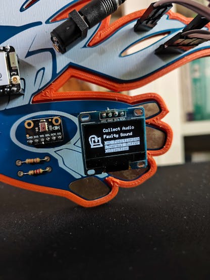
⚠️🔊♨️🖼️ If XIAO ESP32C6 establishes a successful connection with the given Wi-Fi network and all connected components operate as expected, the device shows the home screen on the SSD1306 OLED display.
- Collect Audio
- Faulty Sound
- CNC Positioning & Thermal Buffer Collection
![]()
⚠️🔊♨️🖼️ The device lets the user adjust the highlighted menu option on the home screen by pressing the control buttons — A (↑) and C (↓).
⚠️🔊♨️🖼️ After changing the highlighted menu option, the device also updates the icon on the home screen with the assigned option icon.
⚠️🔊♨️🖼️ As a menu option is highlighted, if the control button B is pressed, the device navigates to the selected option's layout.
⚠️🔊♨️🖼️ Note: If the user presses the control button D, XIAO ESP32C6 returns to the home screen.
![]()
⚠️🔊♨️🖼️ If the user activates the first menu option — Collect Audio:
⚠️🔊♨️🖼️ On the associated layout, the device informs the user of the audio sample collection settings, which allow the user to assign an audio class to the sample by pressing a control button.
- A ➜ normal
- C ➜ defective
![]()
⚠️🔊♨️🖼️ After selecting an audio class, the device checks whether the I2S microphone operates accurately and informs the user regarding the microphone status on the screen before producing an audio sample.
![]()
⚠️🔊♨️🖼️ If the I2S microphone works as expected, the device collects raw audio buffers and transfers them simultaneously to the web application until reaching the predefined buffer multiplier number while maintaining an HTTP POST request.
⚠️🔊♨️🖼️ In this regard, the device can produce and send long raw audio samples to the web application without triggering memory allocation issues.
⚠️🔊♨️🖼️ After concluding the POST request, the device notifies the user of the data transmission success on the screen by showing the associated status icons.
![]()
⚠️🔊♨️🖼️ As explained in the previous steps, after receiving the produced raw audio sample, the web application saves the sample as a plain text file temporarily.
⚠️🔊♨️🖼️ Then, the web application runs a Python script to convert the raw audio sample to a WAV audio file compatible with Edge Impulse.
⚠️🔊♨️🖼️ After converting the given sample with the passed audio conversion parameters successfully, the web application updates the system log on the MariaDB database accordingly.
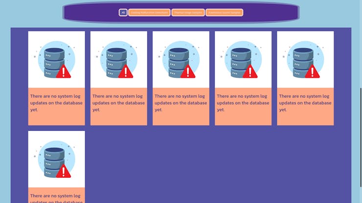
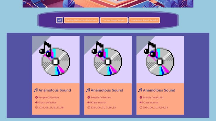
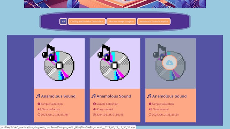
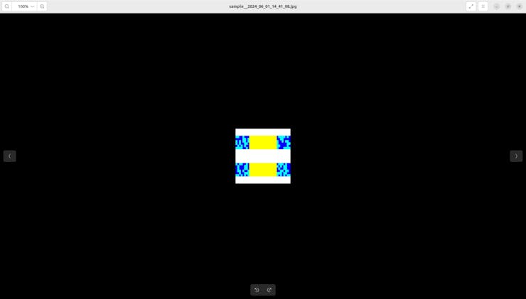
⚠️🔊♨️🖼️ Finally, the web application updates its home (index) page automatically to showcase the latest system log entries. In addition to displaying the collection dates and the assigned audio classes, the web application lets the user download audio samples individually on the home page.
![]()
![]()
![]()
![]()
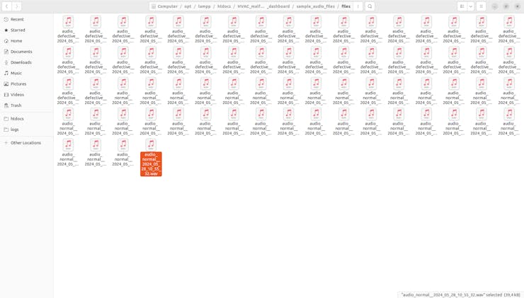
After collecting samples of normal and defective sound originating from the HVAC system cooling fans, I managed to construct a valid audio data set stored on the web application.
![]()
-
24Step 8.a: Controlling CNC (thermal camera container head) motions via Arduino Nano
Since I decided to build a fully 3D-printable custom CNC router to position the MLX90641 thermal imaging camera, I needed to design a separate CNC control mechanism based on Arduino Nano. In this regard, I was able to move the thermal camera container head according to the CNC commands received via serial communication.
After programming XIAO ESP32C6, I focused on improving and refining CNC functions performed by Arduino Nano.
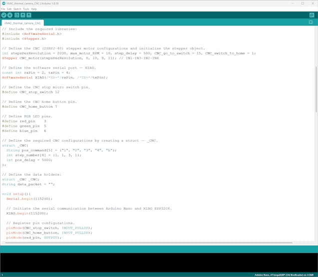
📁 HVAC_thermal_camera_CNC.ino
⭐ Include the required libraries.
#include <SoftwareSerial.h>#include <Stepper.h>
⭐ Define the 28BYJ-48 stepper motor configurations and initialize the stepper object.
int stepsPerRevolution = 2038, max_motor_RPM = 10, step_delay = 500, CNC_go_to_switch = 15, CNC_switch_to_home = 1;Stepper CNC_motor(stepsPerRevolution, 8, 10, 9, 11); // IN1-IN3-IN2-IN4
⭐ Define a software serial port (XIAO) since the default (USB) hardware serial port is occupied for debugging.
const int rxPin = 2, txPin = 4;SoftwareSerial XIAO(/*RX=*/rxPin, /*TX=*/txPin);
⭐ Define all of the required CNC commands and step numbers by creating a struct — _CNC — so as to organize and call them efficiently.
struct _CNC{ String pos_command[5] = {"1", "2", "3", "4", "h"}; int step_number[4] = {1, 1, 3, 1}; int pos_delay = 5000;};⭐ Initiate the defined software serial port to communicate with XIAO ESP32C6.
XIAO.begin(115200);
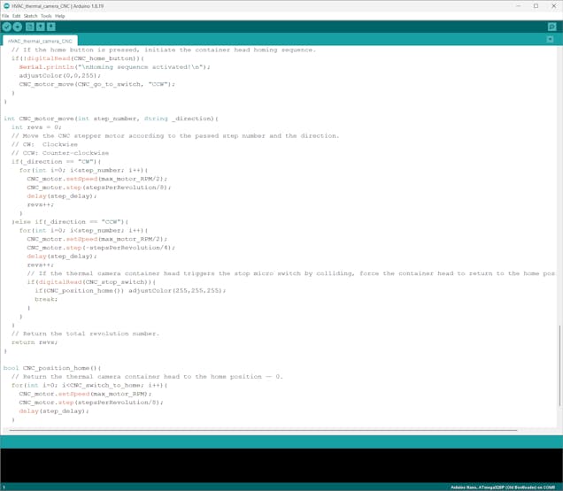
⭐ In the CNC_motor_move function:
⭐ Rotate the stepper motor of the CNC router to move the thermal camera container head according to the passed step number and the direction.
- CW: Clockwise
- CCW: Counter-clockwise
⭐ While turning the stepper motor counter-clockwise, check whether the thermal camera container head triggers the micro switch by colliding.
⭐ If so, force the container head to return to the home position. Then, turn the RGB LED to white.
int CNC_motor_move(int step_number, String _direction){ int revs = 0; // Move the CNC stepper motor according to the passed step number and the direction. // CW: Clockwise // CCW: Counter-clockwise if(_direction == "CW"){ for(int i=0; i<step_number; i++){ CNC_motor.setSpeed(max_motor_RPM/2); CNC_motor.step(stepsPerRevolution/8); delay(step_delay); revs++; } }else if(_direction == "CCW"){ for(int i=0; i<step_number; i++){ CNC_motor.setSpeed(max_motor_RPM/2); CNC_motor.step(-stepsPerRevolution/4); delay(step_delay); revs++; // If the thermal camera container head triggers the stop micro switch by colliding, force the container head to return to the home position. if(digitalRead(CNC_stop_switch)){ if(CNC_position_home()) adjustColor(255,255,255); break; } } } // Return the total revolution number. return revs;}⭐ In the CNC_position_home function, return the thermal camera container head to the home position — 0.
bool CNC_position_home(){ // Return the thermal camera container head to the home position — 0. for(int i=0; i<CNC_switch_to_home; i++){ CNC_motor.setSpeed(max_motor_RPM); CNC_motor.step(stepsPerRevolution/8); delay(step_delay); } return true;}⭐ Obtain the data packet transferred by XIAO ESP32C6 via serial communication.
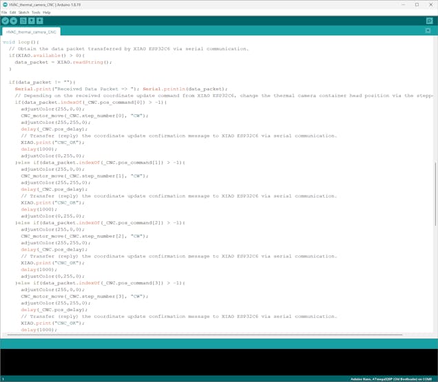
if(XIAO.available() > 0){ data_packet = XIAO.readString(); }⭐ Depending on the received CNC coordinate update command, change the thermal camera container head position by rotating the stepper motor by the predefined step number.
⭐ When starting the positioning process, turn the RGB LED to red. After completing the positioning process, turn the RGB LED to yellow.
⭐ Then, send the coordinate update confirmation message — CNC_OK — to XIAO ESP32C6 via serial communication.
⭐ After sending the confirmation message, turn the RGB LED to green.
⭐ After going through four coordinate updates, if XIAO ESP32C6 transmits the zeroing command, return the thermal camera container head to the starting point (zeroing) by estimating the total revolved step number.
⭐ When starting the zeroing process, turn the RGB LED to red. After completing the zeroing process, turn the RGB LED to yellow.
⭐ Then, send the zeroing confirmation message — CNC_OK — to XIAO ESP32C6 via serial communication.
⭐ After sending the zeroing confirmation message, turn the RGB LED to purple.
⭐ Finally, clear the received data packet.
if(data_packet != ""){ Serial.print("Received Data Packet => "); Serial.println(data_packet); // Depending on the received coordinate update command from XIAO ESP32C6, change the thermal camera container head position via the stepper motor. if(data_packet.indexOf(_CNC.pos_command[0]) > -1){ adjustColor(255,0,0); CNC_motor_move(_CNC.step_number[0], "CW"); adjustColor(255,255,0); delay(_CNC.pos_delay); // Transfer (reply) the coordinate update confirmation message to XIAO ESP32C6 via serial communication. XIAO.print("CNC_OK"); delay(1000); adjustColor(0,255,0); }else if(data_packet.indexOf(_CNC.pos_command[1]) > -1){ adjustColor(255,0,0); CNC_motor_move(_CNC.step_number[1], "CW"); adjustColor(255,255,0); delay(_CNC.pos_delay); // Transfer (reply) the coordinate update confirmation message to XIAO ESP32C6 via serial communication. XIAO.print("CNC_OK"); delay(1000); adjustColor(0,255,0); }else if(data_packet.indexOf(_CNC.pos_command[2]) > -1){ adjustColor(255,0,0); CNC_motor_move(_CNC.step_number[2], "CW"); adjustColor(255,255,0); delay(_CNC.pos_delay); // Transfer (reply) the coordinate update confirmation message to XIAO ESP32C6 via serial communication. XIAO.print("CNC_OK"); delay(1000); adjustColor(0,255,0); }else if(data_packet.indexOf(_CNC.pos_command[3]) > -1){ adjustColor(255,0,0); CNC_motor_move(_CNC.step_number[3], "CW"); adjustColor(255,255,0); delay(_CNC.pos_delay); // Transfer (reply) the coordinate update confirmation message to XIAO ESP32C6 via serial communication. XIAO.print("CNC_OK"); delay(1000); adjustColor(0,255,0); }else if(data_packet.indexOf(_CNC.pos_command[4]) > -1){ // If requested, after going through four coordinate updates, return the thermal camera container head to the starting point (zeroing). int zeroing = 0; for(int i=0; i<4; i++) zeroing+=_CNC.step_number[i]; Serial.print("Zeroing the container head for "); Serial.print(zeroing); Serial.println(" steps!\n"); adjustColor(255,0,0); CNC_motor_move(zeroing, "CCW"); adjustColor(255,255,0); delay(_CNC.pos_delay); // Transfer (reply) the coordinate update confirmation message to XIAO ESP32C6 via serial communication. XIAO.print("CNC_OK"); delay(1000); adjustColor(255,0,255); } // Clear the received data packet. data_packet = ""; }⭐ If the home button is pressed, initiate the container head homing sequence, which returns the container head to the home position (0) by utilizing the micro switch.
if(!digitalRead(CNC_home_button)){ Serial.println("\nHoming sequence activated!\n"); adjustColor(0,0,255); CNC_motor_move(CNC_go_to_switch, "CCW"); }![]()
![]()
![]()
-
25Step 8.b: Communicating with Arduino Nano and the web application to initiate the four-step CNC positioning sequence for consecutive thermal imaging buffer collection via the Particle Cloud
After completing the CNC router programming, controlled by Arduino Nano, I focused on improving the remaining XIAO ESP32C6 features, including transferring commands to Arduino Nano and communicating with the web application regarding thermal imaging buffer collection.
As explained in the previous steps, the device performs lots of interconnected features between different development boards and the web application for data collection and running advanced AI models. Thus, the described code snippets show the different aspects of the same code file. Please refer to the code files or the demonstration videos to inspect all interconnected functions in detail.
📁 HVAC_fault_diagnosis_anomalous_sound.ino
⭐ Define all of the required CNC commands and variables by creating a struct — _CNC — so as to organize and call them efficiently.
struct _CNC{ String pos_command[5] = {"111111111", "222222222", "333333333", "444444444", "hhhhhhhhh"}; int pos_status[4] = {4, 4, 4, 4}; boolean serial_update = false;};⭐ Initiate the hardware serial port (Serial1) to communicate with Arduino Nano.
Serial1.begin(115200, SERIAL_8N1, /*RX=*/D7,/*TX=*/D6);
⭐ In the make_a_get_request function:
⭐ Connect to the web application with the configured server settings.
⭐ Create the query string by appending the passed URL query (GET) parameters.
⭐ Make an HTTP GET request with the given URL parameters to the web application.
⭐ Wait until successfully completing the request process.
boolean make_a_get_request(String request){ // Connect to the web application named HVAC_malfunction_diagnosis_dashboard. Change '80' with '443' if you are using SSL connection. if(client.connect(server, 80)){ // If successful: Serial.println("\nConnected to the web application successfully!\n"); // Create the query string: String query = application + request; // Make an HTTP GET request: client.println("GET " + query + " HTTP/1.1"); client.println("Host: 192.168.1.21"); client.println("Connection: close"); client.println(); // Wait until completing the request process. delay(2000); // If successful: Serial.println("HTTP GET => Connection established!\n"); return true; }else{ Serial.println("\nConnection failed to the web application!\n"); delay(2000); return false; }}⭐ In the nano_update_response function:
⭐ Wait until Arduino Nano transfers a data packet via serial communication.
⭐ Then, return the obtained data packet.
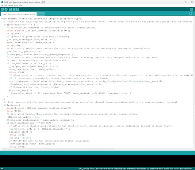
String nano_update_response(){ // Wait until Arduino Nano transfers a data packet via serial communication. String data_packet = ""; while(_CNC.serial_update){ if(Serial1.available() > 0){ data_packet = Serial1.readString(); } if(data_packet != ""){ _CNC.serial_update = false; } delay(1000); } // Then, return the obtained data packet. return data_packet;}⭐ In the thermal_buffer_collection_via_CNC function:
⭐ Initiate the four-step CNC positioning sequence consisting of different CNC commands — from 1 to 4.
⭐ For each CNC positioning command:
⭐ Transfer the given command to Arduino Nano via serial communication.
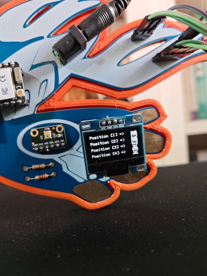
⭐ Update the buffer operation status indicator to Ongoing on the screen with the associated status icon.
⭐ Wait until Arduino Nano replies with the coordinate update confirmation message (CNC_OK) via serial communication after moving the thermal camera container head to the predefined position.
⭐ After obtaining the confirmation message, update the buffer status indicator to Completed on the screen with the associated status icon.
⭐ After positioning the container head according to the passed CNC command, make an HTTP GET request to the web application (dashboard) in order to make Photon 2 collect and register the associated thermal imaging buffer through the Particle Cloud API.
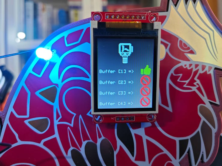
⭐ If the GET request is successful, update the buffer status indicator to Saved on the screen with the associated status icon.
⭐ Then, increase the command number to resume the positioning sequence.
⭐ After concluding the four-step CNC positioning sequence successfully, return the thermal camera container head to the starting point (zeroing) by transmitting the zeroing command to Arduino Nano via serial communication.
⭐ Wait until Arduino Nano replies with the zeroing confirmation message (CNC_OK) via serial communication after moving the thermal camera container head to the starting point.
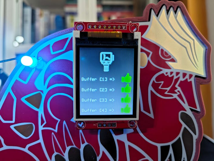
⭐ After obtaining the zeroing confirmation message, change all buffer status indicators on the screen to Image Ready.
⭐ After finalizing the CNC positioning sequence and the zeroing procedure, make a successive HTTP GET request to the web application to initiate the thermal image conversion process with the thermal imaging buffers registered on the Particle Cloud.
⭐ If the GET request is successful, halt all processes and redirect the user to the home screen.
void thermal_buffer_collection_via_CNC(String process_type){ // Initiate the four-step CNC positioning sequence so as to move the thermal camera container head to the predefined points for consecutive data (thermal imaging buffer) collection. if(position_start < 4){ // Transfer CNC commands to Arduino Nano via serial communication. Serial1.print(_CNC.pos_command[position_start]); delay(2000); // Update the given position status to Ongoing. _CNC.pos_status[position_start] = 0; show_interface("CNC", menu_option); delay(500); // Wait until Arduino Nano returns the coordinate update confirmation message via the serial communication. _CNC.serial_update = true; String pos_confirmation = nano_update_response(); // If Arduino Nano transfers the coordinate confirmation message, update the given position status to Completed. // Then, increase the point (position) number. if(pos_confirmation == "CNC_OK"){ _CNC.pos_status[position_start] = 1; show_interface("CNC", menu_option); delay(5000); // After positioning the container head on the given location (point), make an HTTP GET request to the web dashboard in order to make Photon 2 collect and register the associated thermal imaging buffer through the Particle Cloud API. // If registered successfully, update the given position status to Saved. String request = "assets/Particle_cloud_connection.php?collect_particle_cloud_variable="+String(position_start+1); if(make_a_get_request(request)) _CNC.pos_status[position_start] = 2; // Update the position (point) number. position_start++; if(position_start == 4){ show_interface("CNC", menu_option); delay(500); zeroing = true; } } } // After passing all four position points successfully, return the thermal camera container head to the starting point (zeroing). if(zeroing){ Serial1.print(_CNC.pos_command[position_start]); delay(4000); // Wait until Arduino Nano returns the zeroing confirmation message via the serial communication. _CNC.serial_update = true; String zero_confirmation = nano_update_response(); if(zero_confirmation == "CNC_OK"){ // After the container head returns to the starting point, update all position status indicators (icons) to Image Ready. for(int i=0; i<4; i++) _CNC.pos_status[i] = 3; position_start++; delay(1000); zeroing = false; // Notify the user of the latest updated status indicators. show_interface("CNC", menu_option); delay(3000); } } // If Photon 2 registers all thermal imaging buffers successfully and the web dashboard is ready to generate a thermal image from the passed buffers, // make an HTTP GET request to the web dashboard to initiate the thermal image conversion process. if(_CNC.pos_status[0] == 3 && _CNC.pos_status[1] == 3 && _CNC.pos_status[2] == 3 && _CNC.pos_status[3] == 3){ // If the web dashboard generates the thermal image successfully, redirect the user to the home screen. String request = "assets/Particle_cloud_connection.php?generate_cloud_thermal_image="+process_type; if(make_a_get_request(request)){ delay(5000); option_update = false; defective_sound = false; } }}⭐ If the third option (CNC Positioning & Thermal Buffer Collection) is activated:
⭐ Clear the previously assigned buffer status indicators.
⭐ Initiate the four-step CNC positioning sequence so as to move the thermal camera container head to the predefined locations for consecutive thermal scan (imaging) buffer collection through the Particle Cloud API.
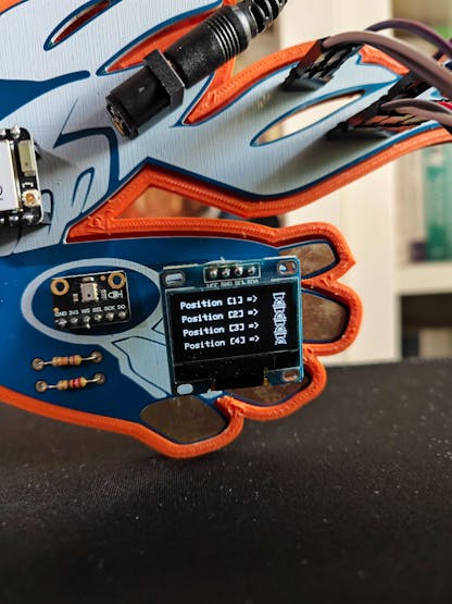
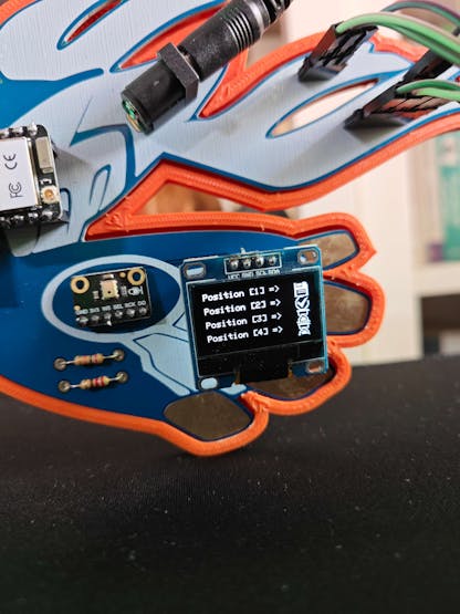
⭐ Notify the user of each buffer status indicator update by showing their associated status icons on the SSD1306 screen — Waiting, Ongoing, Saved, and Image Ready.
⭐ If the control button D is pressed, redirect the user to the home screen.
if(menu_option == 3 && !digitalRead(control_button_B)){ position_start = 0; zeroing = false; option_update = true; // Clear the previously assigned buffer status indicators. for(int i=0; i<4; i++) _CNC.pos_status[i] = 4; while(option_update){ // Notify the user of the CNC positioning status of each individual point by showing their associated status icons on the SSD1306 screen — Waiting, Ongoing, Saved, or Image Ready. show_interface("CNC", menu_option); delay(2000); // Start the CNC positioning sequence and collect thermal scan (imaging) buffers on predefined locations (points) through the Particle Cloud API. thermal_buffer_collection_via_CNC("sample"); // If the control button D is pressed, redirect the user to the home screen. if(!digitalRead(control_button_D)){ option_update = false; } } }![]()
![]()
-
26Step 8.c: Generating the required thermal imaging buffers via a specific color algorithm and registering the produced buffers to Particle Cloud variables
After working on the XIAO ESP32C6 data transmission procedure with the web application and the custom CNC router positioning sequence, I focused on developing and improving Particle Photon 2 functions related to thermal imaging buffer collection and registration.
As discussed earlier, I set up the Particle Workbench on Visual Studio Code (VSCode) to be able to utilize the Particle Device OS to program Photon 2. You can inspect the integrated Particle Cloud transmission methods of the Device OS and their limitations from here.
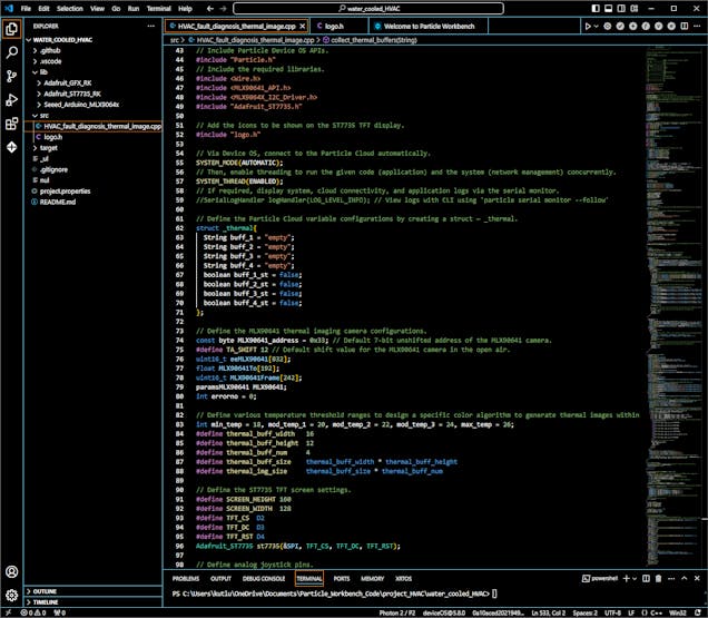
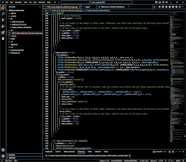
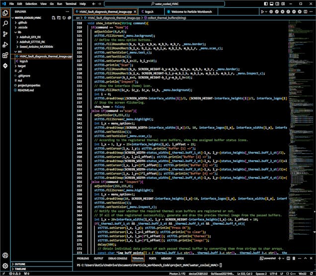
📁 HVAC_fault_diagnosis_thermal_image.cpp
⭐ Include Particle Device OS APIs.
#include "Particle.h"
⭐ Include the required libraries.
#include <Wire.h>#include <MLX90641_API.h>#include <MLX9064X_I2C_Driver.h>#include "Adafruit_ST7735.h"
⭐ Add the icons to be shown on the ST7735 TFT display, which are saved and grouped in the logo.h file.
#include "logo.h"
⭐ Via the built-in Device OS functions, connect to the Particle Cloud automatically.
⭐ Then, enable threading to run the given program (application) and the built-in cloud transmission system (network management) concurrently.
SYSTEM_MODE(AUTOMATIC);SYSTEM_THREAD(ENABLED);
⭐ Define the Particle Cloud variable names and registration status indicators by creating a struct — _thermal — so as to organize and call them efficiently.
struct _thermal{ String buff_1 = "empty"; String buff_2 = "empty"; String buff_3 = "empty"; String buff_4 = "empty"; boolean buff_1_st = false; boolean buff_2_st = false; boolean buff_3_st = false; boolean buff_4_st = false;};⭐ Define the MLX90641 thermal imaging camera configurations, including the 7-bit unshifted device address and the open air shift value.
const byte MLX90641_address = 0x33; // Default 7-bit unshifted address of the MLX90641 camera.#define TA_SHIFT 12 // Default shift value for the MLX90641 camera in the open air.uint16_t eeMLX90641[832];float MLX90641To[192];uint16_t MLX90641Frame[242];paramsMLX90641 MLX90641;int errorno = 0;
⭐ To create a specific color algorithm for converting IR array data items to color-based indicators to produce a thermal imaging buffer, define temperature threshold ranges. Then, define the required information to generate a preview (snapshot) thermal image from the produced buffers.
int min_temp = 18, mod_temp_1 = 20, mod_temp_2 = 22, mod_temp_3 = 24, max_temp = 26;#define thermal_buff_width 16#define thermal_buff_height 12#define thermal_buff_num 4#define thermal_buff_size thermal_buff_width * thermal_buff_height#define thermal_img_size thermal_buff_size * thermal_buff_num
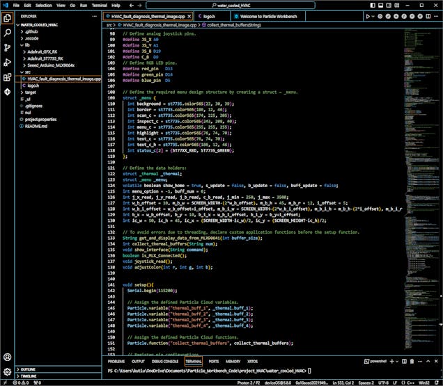
⭐ Configure the ST7735 TFT screen settings.
#define SCREEN_HEIGHT 160#define SCREEN_WIDTH 128#define TFT_CS D2#define TFT_DC D3#define TFT_RST D4Adafruit_ST7735 st7735(&SPI, TFT_CS, TFT_DC, TFT_RST);
⭐ Define the required variables for the home screen and the option layouts by creating a struct — _menu — so as to organize and call them efficiently.
struct _menu { int background = st7735.color565(23, 30, 39); int border = st7735.color565(186, 12, 46); int scan_c = st7735.color565(174, 225, 205); int inspect_c = st7735.color565(243, 208, 40); int menu_c = st7735.color565(255, 255, 255); int highlight = st7735.color565(76, 74, 70); int text_c = st7735.color565(76, 74, 70); int text_c_h = st7735.color565(186, 12, 46); int status_c[2] = {ST77XX_RED, ST7735_GREEN};};⭐ To prevent errors due to threading that manages simultaneous cloud transmission, declare custom application functions before the setup function.
String get_and_display_data_from_MLX90641(int buffer_size);int collect_thermal_buffers(String num);void show_interface(String command);boolean is_MLX_Connected();void joystick_read();void adjustColor(int r, int g, int b);
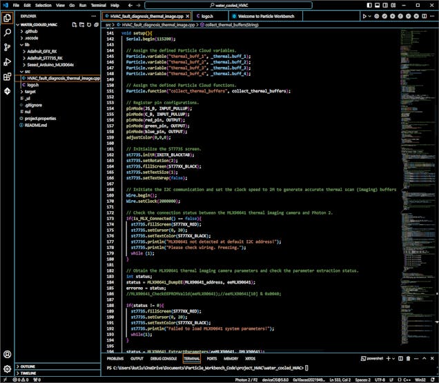
⭐ Assign new variables to the Particle Cloud by utilizing the built-in Particle.variable method.
Particle.variable("thermal_buff_1", _thermal.buff_1); Particle.variable("thermal_buff_2", _thermal.buff_2); Particle.variable("thermal_buff_3", _thermal.buff_3); Particle.variable("thermal_buff_4", _thermal.buff_4);⭐ Assign new functions to the Particle Cloud by utilizing the built-in Particle.function method.
Particle.function("collect_thermal_buffers", collect_thermal_buffers);⭐ Initialize the ST7735 screen with the required configurations.
st7735.initR(INITR_BLACKTAB); st7735.setRotation(2); st7735.fillScreen(ST77XX_BLACK); st7735.setTextSize(1); st7735.setTextWrap(false);
⭐ Initiate the I2C communication and set the clock speed to 2M to generate accurate thermal scan (imaging) buffers via the MLX90641 thermal imaging camera.
Wire.begin(); Wire.setClock(2000000);
⭐ Check the I2C connection success with the MLX90641 thermal imaging camera and the camera parameter extraction status.
⭐ If the thermal imaging camera operates as expected and the parameter extraction is successful, release the eeMLX90641 array and set the refresh rate to 16 Hz.
if(is_MLX_Connected() == false){ st7735.fillScreen(ST77XX_RED); st7735.setCursor(0, 20); st7735.setTextColor(ST77XX_BLACK); st7735.println("MLX90641 not detected at default I2C address!"); st7735.println("Please check wiring. Freezing."); while (1); } // Obtain the MLX90641 thermal imaging camera parameters and check the parameter extraction status. int status; status = MLX90641_DumpEE(MLX90641_address, eeMLX90641); errorno = status; //MLX90641_CheckEEPROMValid(eeMLX90641);//eeMLX90641[10] & 0x0040; if(status != 0){ st7735.fillScreen(ST77XX_RED); st7735.setCursor(0, 20); st7735.setTextColor(ST77XX_BLACK); st7735.println("Failed to load MLX90641 system parameters!"); while(1); } status = MLX90641_ExtractParameters(eeMLX90641, &MLX90641); if(status != 0){ st7735.fillScreen(ST77XX_RED); st7735.setCursor(0, 20); st7735.setTextColor(ST77XX_BLACK); st7735.println("MLX90641 parameter extraction failed!"); while(1); } // Once the MLX90641 parameters are extracted successfully, release the eeMLX90641 array and set the refresh rate to 16 Hz. MLX90641_SetRefreshRate(MLX90641_address, 0x05);⭐ According to the analog joystick movements (UP or DOWN), adjust the highlighted menu option number and the screen update status.
joystick_read(); if(j_y_read > j_max) { menu_option = 0; b_update = true; delay(500); } if(j_y_read < j_min) { menu_option = 1; b_update = true; delay(500); }⭐ In the show_interface function:
⭐ According to the passed screen command and the menu option number, show the default home screen or the selected option layout.
⭐ Stop the home screen flickering by showing it for once when requested in the loop.
⭐ If the screen command is scan:
⭐ Show the associated interface icon on the layout.
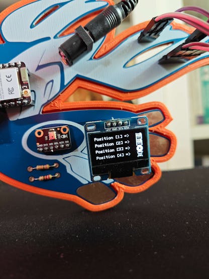
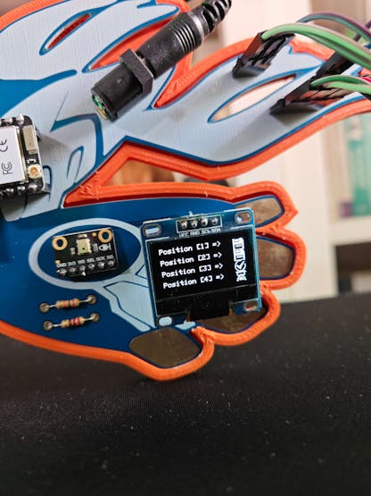
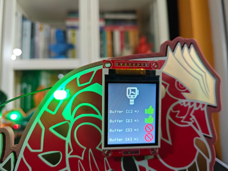
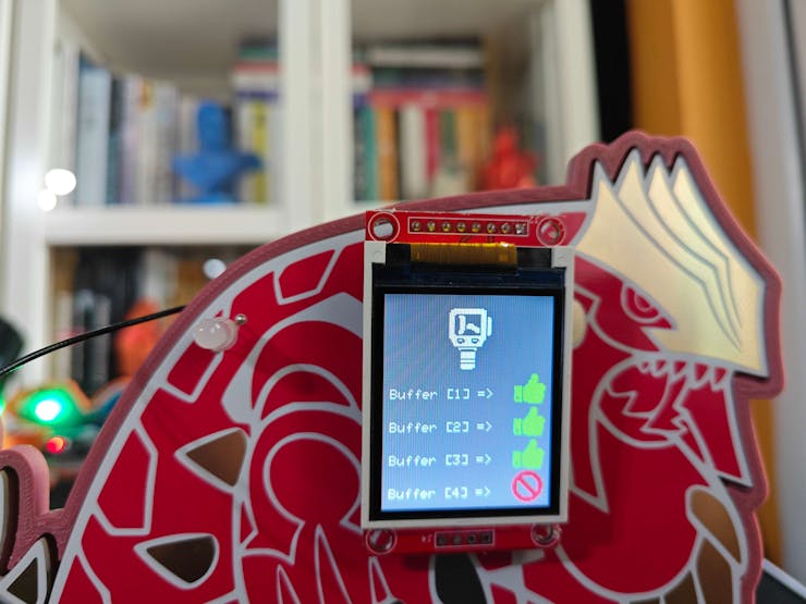
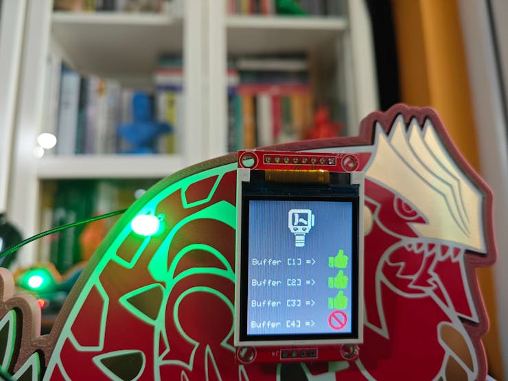
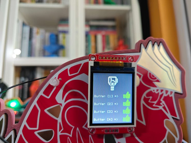
⭐ Then, display the registration status indicators for each thermal imaging buffer with the assigned icons.
⭐ If the screen command is inspect:
⭐ Show the associated interface icon on the layout.
⭐ If all thermal scan (imaging) buffers are collected and registered successfully:
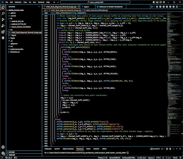
⭐ Obtain individual data points of each produced thermal buffer by converting them from strings to char arrays.
⭐ For each passed thermal imaging buffer ((16x12) x 4):
⭐ Define the coordinates for the first pixel.
⭐ Starting with the first pixel, draw each individual data point with the color indicator to display an accurate preview thermal image on the screen, estimated by the specific color algorithm based on the defined temperature threshold ranges.
⭐ After drawing a pixel successfully, update the successive data point coordinates.
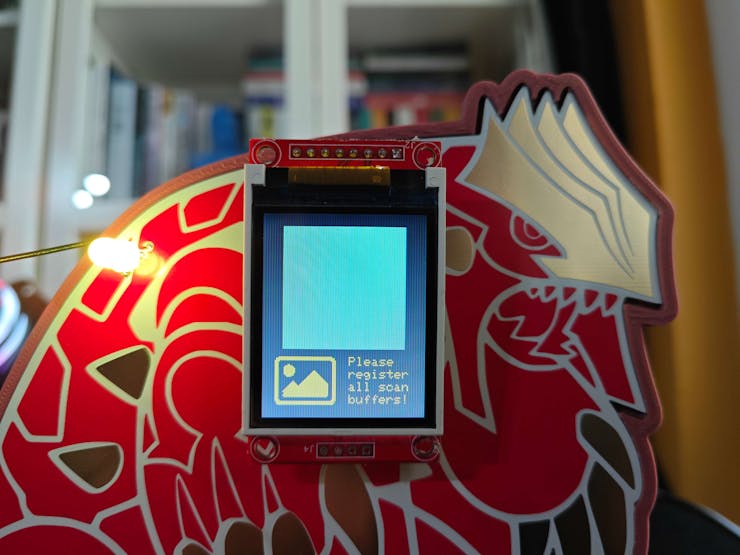
⭐ If the registered thermal buffers do not meet the requirements, show the blank preview image to notify the user.
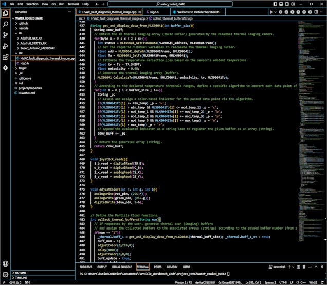
void show_interface(String command){ if(command == "home"){ adjustColor(0,0,0); st7735.fillScreen(_menu.background); // Define the menu option buttons. st7735.fillRoundRect(b_x, b_y, m_b_w, m_b_h, m_b_r, _menu.border); st7735.fillRoundRect(b_i_x, b_i_y, m_b_i_w, m_b_i_h, m_b_i_r, _menu.scan_c); st7735.setTextColor(_menu.text_c); st7735.setTextSize(2); st7735.setCursor(b_i_x+25, b_i_y+10); st7735.println("Scan"); st7735.fillRoundRect(b_x, SCREEN_HEIGHT-b_y-m_b_h, m_b_w, m_b_h, m_b_r, _menu.border); st7735.fillRoundRect(b_i_x, SCREEN_HEIGHT-b_i_y-m_b_i_h, m_b_i_w, m_b_i_h, m_b_i_r, _menu.inspect_c); st7735.setCursor(b_i_x+8, SCREEN_HEIGHT-b_i_y-m_b_i_h+10); st7735.println("Inspect"); // Show the interface (home) icon. st7735.fillRect(ic_x, ic_y, ic_w, ic_h, _menu.background); int i = 0; st7735.drawBitmap((SCREEN_WIDTH-interface_widths[i])/2, (SCREEN_HEIGHT-interface_heights[i])/2, interface_logos[i], interface_widths[i], interface_heights[i], _menu.menu_c); // Stop the screen flickering. show_home = false; }else if(command =="scan"){ adjustColor(0,255,1); st7735.fillScreen(_menu.highlight); int i_x = menu_option+1; st7735.drawBitmap((SCREEN_WIDTH-interface_widths[i_x])/2, 10, interface_logos[i_x], interface_widths[i_x], interface_heights[i_x], _menu.scan_c); st7735.setTextSize(1); st7735.setTextColor(_menu.scan_c); // According to the registered thermal scan buffers, show the assigned buffer status icons. int l_x = 5, l_y = 25+interface_heights[i_x], l_offset = 25; st7735.setCursor(l_x, l_y); st7735.println("Buffer [1] =>"); st7735.drawBitmap(SCREEN_WIDTH-status_widths[_thermal.buff_1_st]-l_x, l_y-(status_heights[_thermal.buff_1_st]/2), status_logos[_thermal.buff_1_st], status_widths[_thermal.buff_1_st], status_heights[_thermal.buff_1_st], _menu.status_c[_thermal.buff_1_st]); st7735.setCursor(l_x, l_y+l_offset); st7735.println("Buffer [2] =>"); st7735.drawBitmap(SCREEN_WIDTH-status_widths[_thermal.buff_2_st]-l_x, l_y-(status_heights[_thermal.buff_2_st]/2)+l_offset, status_logos[_thermal.buff_2_st], status_widths[_thermal.buff_2_st], status_heights[_thermal.buff_2_st], _menu.status_c[_thermal.buff_2_st]); st7735.setCursor(l_x, l_y+(2*l_offset)); st7735.println("Buffer [3] =>"); st7735.drawBitmap(SCREEN_WIDTH-status_widths[_thermal.buff_3_st]-l_x, l_y-(status_heights[_thermal.buff_3_st]/2)+(2*l_offset), status_logos[_thermal.buff_3_st], status_widths[_thermal.buff_3_st], status_heights[_thermal.buff_3_st], _menu.status_c[_thermal.buff_3_st]); st7735.setCursor(l_x, l_y+(3*l_offset)); st7735.println("Buffer [4] =>"); st7735.drawBitmap(SCREEN_WIDTH-status_widths[_thermal.buff_4_st]-l_x, l_y-(status_heights[_thermal.buff_4_st]/2)+(3*l_offset), status_logos[_thermal.buff_4_st], status_widths[_thermal.buff_4_st], status_heights[_thermal.buff_4_st], _menu.status_c[_thermal.buff_4_st]); }else if(command == "inspect"){ adjustColor(255,255,0); st7735.fillScreen(_menu.highlight); int i_x = menu_option+1; st7735.drawBitmap(10, SCREEN_HEIGHT-interface_heights[i_x]-10, interface_logos[i_x], interface_widths[i_x], interface_heights[i_x], _menu.inspect_c); st7735.setTextSize(1); st7735.setTextColor(_menu.inspect_c); // Notify the user whether the required thermal scan buffers are registered or not. // If all of them registered successfully, generate and draw the preview thermal image from the passed buffers. int l_x = 20+interface_widths[i_x], l_y = SCREEN_HEIGHT-interface_heights[i_x]-10, l_offset = 10; if(_thermal.buff_1_st && _thermal.buff_2_st && _thermal.buff_3_st && _thermal.buff_4_st){ st7735.setCursor(l_x, l_y); st7735.println("Press OK"); st7735.setCursor(l_x, l_y+l_offset); st7735.println("to clear"); st7735.setCursor(l_x, l_y+(2*l_offset)); st7735.println("thermal"); st7735.setCursor(l_x, l_y+(3*l_offset)); st7735.println("image!"); delay(500); // Obtain individual data points of each passed thermal buffer by converting them from strings to char arrays. const char *img_buff_points[] = {_thermal.buff_1.c_str(), _thermal.buff_2.c_str(), _thermal.buff_3.c_str(), _thermal.buff_4.c_str()}; // Generate the preview thermal image [{16x12} x 4] by applying the specific color algorithm based on the defined temperature ranges. int p_w = 3, p_h = 4, img_x, img_x_s, img_y, img_y_s, p_num = 1, y_off = 10; int img_w = thermal_buff_width*p_w, img_h = thermal_buff_height*p_h; for(int t = 0; t < thermal_buff_num; t++){ // Define buffer starting points. if(t==0) img_x = img_x_s = (SCREEN_WIDTH-(img_w*2))/2, img_y = img_y_s = y_off; if(t==1) img_x = img_x_s = (SCREEN_WIDTH/2), img_y = img_y_s = y_off; if(t==2) img_x = img_x_s = (SCREEN_WIDTH-(img_w*2))/2, img_y = img_y_s = y_off+img_h; if(t==3) img_x = img_x_s = (SCREEN_WIDTH/2), img_y = img_y_s = y_off+img_h; for(int i = 0; i < thermal_buff_size; i++){ // Draw individual data points of each thermal buffer with the color indicator estimated by the given algorithm to generate a precise thermal image. switch(img_buff_points[t][i]){ case 'w': st7735.fillRect(img_x, img_y, p_w, p_h, ST77XX_WHITE); break; case 'c': st7735.fillRect(img_x, img_y, p_w, p_h, ST77XX_CYAN); break; case 'b': st7735.fillRect(img_x, img_y, p_w, p_h, ST77XX_BLUE); break; case 'y': st7735.fillRect(img_x, img_y, p_w, p_h, ST77XX_YELLOW); break; case 'o': st7735.fillRect(img_x, img_y, p_w, p_h, st7735.color565(255, 165, 0)); break; case 'r': st7735.fillRect(img_x, img_y, p_w, p_h, ST77XX_RED); break; } // Update the successive data point coordinates. img_x += p_w; if(p_num==thermal_buff_width){ img_x = img_x_s; img_y += p_h; p_num=0; } p_num+=1; } } }else{ st7735.setCursor(l_x, l_y); st7735.println("Please"); st7735.setCursor(l_x, l_y+l_offset); st7735.println("register"); st7735.setCursor(l_x, l_y+(2*l_offset)); st7735.println("all scan"); st7735.setCursor(l_x, l_y+(3*l_offset)); st7735.println("buffers!"); // If the registered buffers do not meet the requirements, show the blank thermal image — template. int p_w = 3, p_h = 4; int img_w = thermal_buff_width*p_w*2, img_h = thermal_buff_height*p_h*2, img_x = (SCREEN_WIDTH-img_w)/2, img_y = 10; st7735.fillRect(img_x, img_y, img_w, img_h, st7735.color565(144, 238, 144)); } }}⭐ In the get_and_display_data_from_MLX90641 function:
⭐ Get the required variables generated by the MLX90641 thermal imaging camera to calculate the IR array (16x12).
⭐ Estimate the temperature reflection loss based on the sensor's ambient temperature.
⭐ Then, compute and store the IR array.
⭐ Apply the specific algorithm based on the defined temperature ranges to convert each data point of the given IR array to color-based indicators.
⭐ Then, produce the thermal scan (imaging) buffer by appending each evaluated color indicator to the given string variable.
⭐ Finally, return the produced thermal imaging buffer — string.
String get_and_display_data_from_MLX90641(int buffer_size){ String conv_buff; // Obtain the IR thermal imaging array (16x12 buffer) generated by the MLX90641 thermal imaging camera. for(byte x = 0 ; x < 2 ; x++){ int status = MLX90641_GetFrameData(MLX90641_address, MLX90641Frame); // Get the required MLX90641 variables to calculate the thermal imaging buffer. float vdd = MLX90641_GetVdd(MLX90641Frame, &MLX90641); float Ta = MLX90641_GetTa(MLX90641Frame, &MLX90641); // Estimate the temperature reflection loss based on the sensor's ambient temperature. float tr = Ta - TA_SHIFT; float emissivity = 0.95; // Generate the thermal imaging array (buffer). MLX90641_CalculateTo(MLX90641Frame, &MLX90641, emissivity, tr, MLX90641To); } // According to the declared temperature threshold ranges, define a specific algorithm to convert each data point of the given thermal buffer to color-based indicators. for(int i = 0 ; i < buffer_size ; i++){ String _p; // Assess and assign a color-based indicator for the passed data point via the algorithm. if(MLX90641To[i] <= min_temp) _p = 'w'; if(MLX90641To[i] > min_temp && MLX90641To[i] <= mod_temp_1) _p = 'c'; if(MLX90641To[i] > mod_temp_1 && MLX90641To[i] <= mod_temp_2) _p = 'b'; if(MLX90641To[i] > mod_temp_2 && MLX90641To[i] <= mod_temp_3) _p = 'y'; if(MLX90641To[i] > mod_temp_3 && MLX90641To[i] <= max_temp) _p = 'o'; if(MLX90641To[i] > max_temp) _p = 'r'; // Append the evaluated indicator as a string item to register the given buffer as an array (string). conv_buff += _p; } // Return the generated array (string). return conv_buff;}⭐ After changing the menu option number, highlight the selected option and show the associated icon on the home screen.
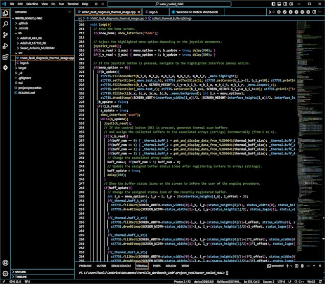
⭐ After highlighting a menu option on the home screen, if the joystick button is pressed, navigate to the selected option's layout.
⭐ If the first option (Scan) is activated:
⭐ If the control button OK is pressed, produce a thermal imaging buffer and assign the generated buffer to the predefined string variable linked to the Particle Cloud variable according to the current buffer number — from 0 to 3. Also, update the associated buffer registration status indicator as registered.
⭐ Then, increase the buffer number incrementally.
⭐ After registering thermal buffers, show the buffer status indicators with the assigned icons on the screen to inform the user of the ongoing procedure.
⭐ To avoid flickering, only update the latest changed buffer status indicator.
⭐ If the analog joystick moves to the left, redirect the user to the default home screen.
#️⃣ As mentioned earlier, the string variables are linked to the Particle Cloud variables. Since Photon 2 updates the cloud variables automatically when the linked variables are modified, do not forget to add delays in while loops. Otherwise, the while loop interrupts and blocks the Particle Cloud network connection (threading).
if(menu_option == 0){ if(b_update){ st7735.fillRoundRect(b_i_x, b_i_y, m_b_i_w, m_b_i_h, m_b_i_r, _menu.highlight); st7735.setTextColor(_menu.text_c_h); st7735.setTextSize(2); st7735.setCursor(b_i_x+25, b_i_y+10); st7735.println("Scan"); st7735.fillRoundRect(b_i_x, SCREEN_HEIGHT-b_i_y-m_b_i_h, m_b_i_w, m_b_i_h, m_b_i_r, _menu.inspect_c); st7735.setTextColor(_menu.text_c); st7735.setCursor(b_i_x+8, SCREEN_HEIGHT-b_i_y-m_b_i_h+10); st7735.println("Inspect"); st7735.fillRect(ic_x, ic_y, ic_w, ic_h, _menu.background); int i_x = menu_option+1; st7735.drawBitmap((SCREEN_WIDTH-interface_widths[i_x])/2, (SCREEN_HEIGHT-interface_heights[i_x])/2, interface_logos[i_x], interface_widths[i_x], interface_heights[i_x], _menu.scan_c); }b_update = false; if(!j_b_read){ s_update = true; show_interface("scan"); while(s_update){ joystick_read(); // If the control button (OK) is pressed, generate thermal scan buffers // and assign the collected buffers to the associated arrays (strings) incrementally (from 1 to 4). if(!c_b_read){ if(buff_num == 0) { _thermal.buff_1 = get_and_display_data_from_MLX90641(thermal_buff_size); _thermal.buff_1_st = true;} if(buff_num == 1) { _thermal.buff_2 = get_and_display_data_from_MLX90641(thermal_buff_size); _thermal.buff_2_st = true;} if(buff_num == 2) { _thermal.buff_3 = get_and_display_data_from_MLX90641(thermal_buff_size); _thermal.buff_3_st = true;} if(buff_num == 3) { _thermal.buff_4 = get_and_display_data_from_MLX90641(thermal_buff_size); _thermal.buff_4_st = true;} // Change the associated array number. buff_num++; if(buff_num > 3) buff_num = 0; // Update the assigned buffer status icons after registering buffers to arrays (strings). buff_update = true; delay(250); } // Show the buffer status icons on the screen to inform the user of the ongoing procedure. if(buff_update){ // Change the assigned status icon of the recently registered buffer. int i_x = menu_option+1, l_x = 5, l_y = 25+interface_heights[i_x], l_offset = 25; if(_thermal.buff_1_st){ st7735.fillRect(SCREEN_WIDTH-status_widths[0]-l_x, l_y-(status_heights[0]/2), status_widths[0], status_heights[0], _menu.highlight); st7735.drawBitmap(SCREEN_WIDTH-status_widths[1]-l_x, l_y-(status_heights[1]/2), status_logos[1], status_widths[1], status_heights[1], _menu.status_c[1]); } if(_thermal.buff_2_st){ st7735.fillRect(SCREEN_WIDTH-status_widths[0]-l_x, l_y-(status_heights[0]/2)+l_offset, status_widths[0], status_heights[0], _menu.highlight); st7735.drawBitmap(SCREEN_WIDTH-status_widths[1]-l_x, l_y-(status_heights[1]/2)+l_offset, status_logos[1], status_widths[1], status_heights[1], _menu.status_c[1]); } if(_thermal.buff_3_st){ st7735.fillRect(SCREEN_WIDTH-status_widths[0]-l_x, l_y-(status_heights[0]/2)+(2*l_offset), status_widths[0], status_heights[0], _menu.highlight); st7735.drawBitmap(SCREEN_WIDTH-status_widths[1]-l_x, l_y-(status_heights[1]/2)+(2*l_offset), status_logos[1], status_widths[1], status_heights[1], _menu.status_c[1]); } if(_thermal.buff_4_st){ st7735.fillRect(SCREEN_WIDTH-status_widths[0]-l_x, l_y-(status_heights[0]/2)+(3*l_offset), status_widths[0], status_heights[0], _menu.highlight); st7735.drawBitmap(SCREEN_WIDTH-status_widths[1]-l_x, l_y-(status_heights[1]/2)+(3*l_offset), status_logos[1], status_widths[1], status_heights[1], _menu.status_c[1]); } // Avoid flickering. buff_update = false; } // Do not forget to add delays in while loops. Otherwise, the while loop interrupts the Particle Cloud network connection. delay(2000); // If the X-axis of the joystick moves to the left, redirect the user to the home screen. if(j_x_read > j_max){ s_update = false; show_home = true; menu_option = -1; } } } }⭐ If the second option (Inspect) is activated:
⭐ Display the preview thermal image generated from the registered thermal imaging buffers on the layout.
⭐ If the registered thermal buffers do not meet the requirements, show the blank preview image.
⭐ If the control button OK is pressed, clear all registered thermal scan buffers and set their status indicators as blank. Then, remove the latest preview thermal image by displaying the blank one.
⭐ If the analog joystick moves to the left, redirect the user to the default home screen.
#️⃣ Do not forget to add delays in while loops. Otherwise, the while loop interrupts and blocks the Particle Cloud network connection (threading).
if(menu_option == 1){ if(b_update){ st7735.fillRoundRect(b_i_x, b_i_y, m_b_i_w, m_b_i_h, m_b_i_r, _menu.scan_c); st7735.setTextColor(_menu.text_c); st7735.setTextSize(2); st7735.setCursor(b_i_x+25, b_i_y+10); st7735.println("Scan"); st7735.fillRoundRect(b_i_x, SCREEN_HEIGHT-b_i_y-m_b_i_h, m_b_i_w, m_b_i_h, m_b_i_r, _menu.highlight); st7735.setTextColor(_menu.text_c_h); st7735.setCursor(b_i_x+8, SCREEN_HEIGHT-b_i_y-m_b_i_h+10); st7735.println("Inspect"); st7735.fillRect(ic_x, ic_y, ic_w, ic_h, _menu.background); int i_x = menu_option+1; st7735.drawBitmap((SCREEN_WIDTH-interface_widths[i_x])/2, (SCREEN_HEIGHT-interface_heights[i_x])/2, interface_logos[i_x], interface_widths[i_x], interface_heights[i_x], _menu.inspect_c); }b_update = false; if(!j_b_read){ s_update = true; show_interface("inspect"); while(s_update){ joystick_read(); // If the control button (OK) is pressed, clear all thermal scan buffers and the latest generated thermal image. if(!c_b_read){ _thermal.buff_1 = _thermal.buff_2 = _thermal.buff_3 = _thermal.buff_4 = "empty"; _thermal.buff_1_st = _thermal.buff_2_st = _thermal.buff_3_st = _thermal.buff_4_st = false; buff_num = 0; delay(500); show_interface("inspect"); delay(500); } // Do not forget to add delays in while loops. Otherwise, the while loop interrupts the Particle Cloud network connection. delay(2000); // If the X-axis of the joystick moves to the left, redirect the user to the home screen. if(j_x_read > j_max){ s_update = false; show_home = true; menu_option = -1; } } } }⭐ In the collect_thermal_buffers function:
#️⃣ As discussed earlier, this function is linked to a Particle Cloud function. Thus, the Particle Cloud API can access and execute the given function remotely.
⭐ According to the passed buffer number (from 1 to 4), produce a thermal imaging buffer and assign the generated buffer to the predefined string variable linked to the Particle Cloud variable.
⭐ Also, update the associated buffer status indicator as registered and blink the RGB LED as green to notify the user of the buffer registration success.
⭐ If requested, clear all registered thermal scan buffers and set their status indicators as blank.
int collect_thermal_buffers(String num){ // If requested by the user, generate thermal scan (imaging) buffers // and assign the collected buffers to the associated arrays (strings) according to the passed buffer number (from 1 to 4). if(num == "1"){ _thermal.buff_1 = get_and_display_data_from_MLX90641(thermal_buff_size); _thermal.buff_1_st = true; buff_num = 1; adjustColor(0,255,0); delay(1000); adjustColor(0,0,0); buff_update = true; return buff_num; }else if(num == "2"){ _thermal.buff_2 = get_and_display_data_from_MLX90641(thermal_buff_size); _thermal.buff_2_st = true; buff_num = 2; adjustColor(0,255,0); delay(1000); adjustColor(0,0,0); buff_update = true; return buff_num; }else if(num == "3"){ _thermal.buff_3 = get_and_display_data_from_MLX90641(thermal_buff_size); _thermal.buff_3_st = true; buff_num = 3; adjustColor(0,255,0); delay(1000); adjustColor(0,0,0); buff_update = true; return buff_num; }else if(num == "4"){ _thermal.buff_4 = get_and_display_data_from_MLX90641(thermal_buff_size); _thermal.buff_4_st = true; buff_num = 4; adjustColor(0,255,0); delay(1000); adjustColor(0,0,0); buff_update = true; return buff_num; }else if(num == "clear"){ // If requested, clear all thermal scan buffers. _thermal.buff_1 = _thermal.buff_2 = _thermal.buff_3 = _thermal.buff_4 = "empty"; _thermal.buff_1_st = _thermal.buff_2_st = _thermal.buff_3_st = _thermal.buff_4_st = false; buff_num = 0; adjustColor(0,0,1); delay(1000); adjustColor(0,0,0); buff_update = true; return buff_num; }else{ adjustColor(255,0,0); delay(1000); adjustColor(0,0,0); return -1; }}![]()
![]()
![]()
![]()
![]()
![]()
![]()
![]()
-
27Step 8.d: Producing accurate thermal images from the registered buffers and saving them as samples via the web application
⚠️🔊♨️🖼️ If the user presses the home button, Arduino Nano homes the thermal camera container head by employing the micro switch on the CNC router.
⚠️🔊♨️🖼️ When the homing sequence starts, Arduino Nano turns the RGB LED to blue. After returning the container head to the home position (0), it turns the RGB LED to white.
![]()
![]()
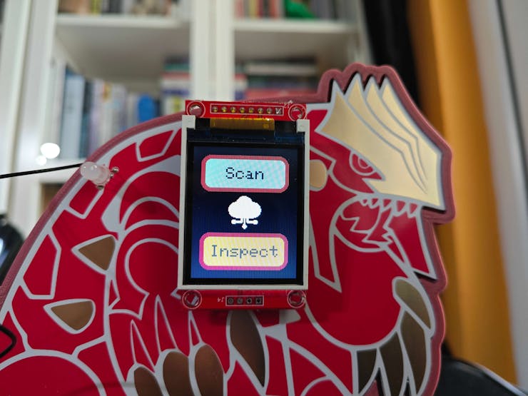
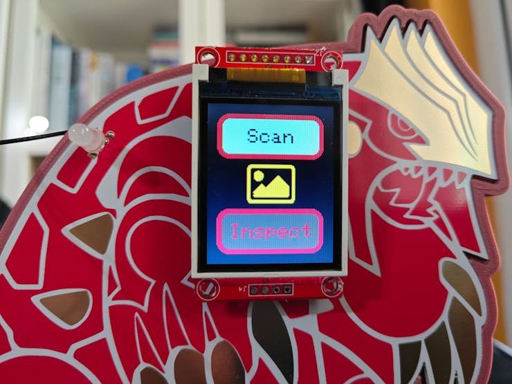
⚠️🔊♨️🖼️ If Particle Photon 2 establishes a successful connection with the Particle Cloud and all connected components operate as expected, the device shows the home screen on the ST7735 TFT display.
- Scan
- Inspect
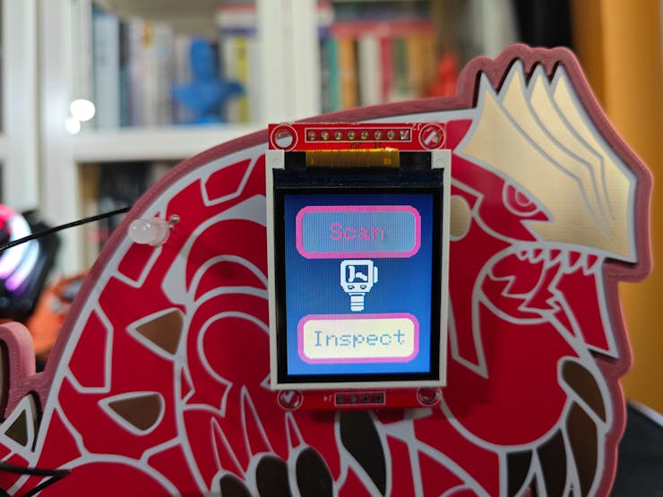
⚠️🔊♨️🖼️ The device lets the user adjust the highlighted menu option on the home screen by moving the analog joystick — UP (↑) and DOWN (↓).
⚠️🔊♨️🖼️ After changing the highlighted menu option, the device also updates the icon on the home screen with the assigned option icon.
⚠️🔊♨️🖼️ As a menu option is highlighted, if the joystick button is pressed, the device navigates to the selected option's layout.
⚠️🔊♨️🖼️ Note: If the user moves the joystick to the left, Photon 2 returns to the default home screen.
![]()
⚠️🔊♨️🖼️ If the user activates the first menu option — Scan:
⚠️🔊♨️🖼️ The device shows the current buffer registration status indicators with the assigned icons on the screen to inform the user of the ongoing procedure. Then, the device turns the RGB LED to cyan.
⚠️🔊♨️🖼️ The device lets the user manually produce thermal imaging buffers and register the generated buffers to the linked Particle Cloud variables by pressing the control button OK. For each press, the device registers the produced buffer to the Particle Cloud incrementally — from 1 to 4.
⚠️🔊♨️🖼️ After registering a thermal imaging buffer successfully, the device updates the associated buffer status indicator as registered.
![]()
![]()
![]()
![]()
![]()
![]()
#️⃣ Since XIAO ESP32C6 communicates with the web application (dashboard) to handle the thermal imaging buffer collection in sync with the four-step CNC positioning sequence, the following descriptions show features performed by XIAO ESP32C6 and Photon 2 in tandem.
⚠️🔊♨️🖼️ If the user activates the third menu option provided by XIAO ESP32C6 — CNC Positioning & Thermal Buffer Collection:
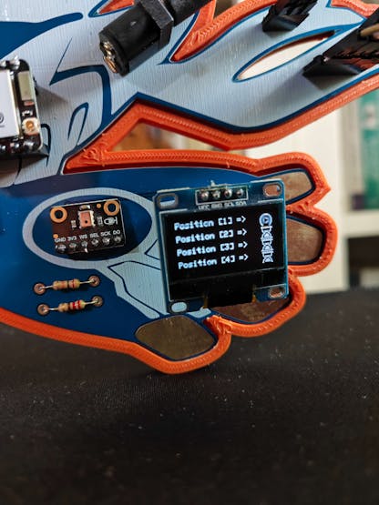
⚠️🔊♨️🖼️ The device shows the buffer operation status indicators with the assigned icons on the SSD1306 OLED display for each thermal imaging buffer as Waiting.
![]()
![]()
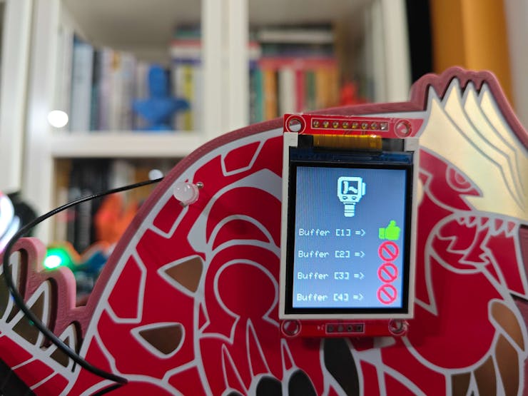
⚠️🔊♨️🖼️ XIAO ESP32C6 transfers the first CNC positioning command to Arduino Nano via serial communication to initiate the four-step CNC positioning sequence. Then, the device updates the first buffer operation status indicator to Ongoing.
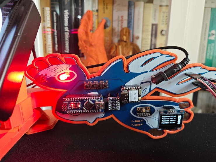
⚠️🔊♨️🖼️ After XIAO ESP32C6 sends a CNC positioning command, Arduino Nano informs the user of the positioning process by adjusting the RGB LED color.
- Red ➡ command received via serial communication
- Yellow ➡ the positioning process is completed
- Green ➡ the coordinate update confirmation message — CNC_OK — sent (replied) to XIAO ESP32C6 via serial communication
⚠️🔊♨️🖼️ After receiving the coordinate update confirmation message, XIAO ESP32C6 updates the associated buffer operation status indicator to Completed on the screen.
![]()
![]()
![]()
![]()
![]()
⚠️🔊♨️🖼️ Then, XIAO ESP32C6 makes an HTTP GET request to the web dashboard in order to make Photon 2 produce a thermal imaging buffer and register the generated buffer to the first linked cloud variable via the Particle Cloud API.
⚠️🔊♨️🖼️ After making the GET request successfully, the device updates the associated buffer operation status indicator to Saved on the screen.
![]()
⚠️🔊♨️🖼️ After the web application runs the linked cloud function via the Particle Cloud API, Photon 2 employs the MLX90641 thermal imaging camera to generate a 16x12 IR array.
⚠️🔊♨️🖼️ Then, Photon 2 applies the specific color algorithm to convert the generated IR array to a thermal imaging buffer based on the predefined temperature thresholds.
- 'w' ➜ White
- 'c' ➜ Cyan
- 'b' ➜ Blue
- 'y' ➜ Yellow
- 'o' ➜ Orange
- 'r' ➜ Red
⚠️🔊♨️🖼️ After producing the thermal imaging buffer successfully, Photon 2 turns the RGB LED to green and updates the first buffer registration status indicator to registered.
⚠️🔊♨️🖼️ Since Photon 2 updates the cloud variables automatically as the linked program variables are modified, the produced thermal imaging buffer is registered to the first linked cloud variable automatically.
⚠️🔊♨️🖼️ Then, the device turns off the RGB LED.
![]()
![]()
![]()
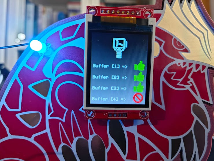
⚠️🔊♨️🖼️ Until concluding the four-step CNC positioning sequence and registering all required thermal imaging buffers to the Particle Cloud, the device repeats the same procedure.
![]()
![]()
![]()
![]()
![]()
![]()
![]()
![]()
![]()
![]()
![]()
![]()
![]()
![]()
![]()
⚠️🔊♨️🖼️ After finalizing the four-step CNC positioning sequence, XIAO ESP32C6 transmits the CNC zeroing command to Arduino Nano via serial communication.
⚠️🔊♨️🖼️ Then, Arduino Nano returns the thermal camera container head to the starting point (zeroing) by estimating the total revolved step number.
⚠️🔊♨️🖼️ After XIAO ESP32C6 sends the zeroing command, Arduino Nano informs the user of the zeroing process by adjusting the RGB LED color.
- Red ➡ command received via serial communication
- Yellow ➡ the zeroing process is completed
- Purple ➡ the zeroing confirmation message — CNC_OK — sent (replied) to XIAO ESP32C6 via serial communication
⚠️🔊♨️🖼️ After obtaining the zeroing confirmation message, XIAO ESP32C6 updates all buffer operation status indicators to Image Ready on the screen.
![]()
![]()
![]()
![]()
⚠️🔊♨️🖼️ Then, XIAO ESP32C6 makes an HTTP GET request to the web dashboard in order to obtain all thermal imaging buffers registered on the Particle Cloud via the Particle Cloud API.
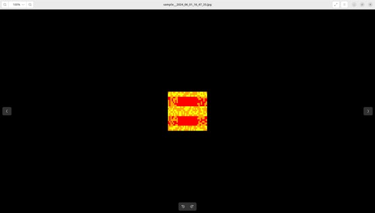
⚠️🔊♨️🖼️ As discussed in the previous steps, the web dashboard produces a precise thermal image (192 x 192) from the obtained buffers and saves the generated image on the server by running a Python script.
⚠️🔊♨️🖼️ After producing an accurate thermal image with the passed thermal imaging buffers successfully, the web application updates the system log on the MariaDB database accordingly.
⚠️🔊♨️🖼️ Finally, the web application updates its home (index) page automatically to showcase the latest system log entries. In addition to displaying the sample images and the collection dates, the web application lets the user download image samples individually on the home page.
![]()
⚠️🔊♨️🖼️ If the user activates the second menu option provided by Photon 2 — Inspect:
⚠️🔊♨️🖼️ The device turns the RGB LED to yellow.
⚠️🔊♨️🖼️ The device draws each individual data point (color-based indicator) of the registered buffers on the ST7735 TFT display to show an accurate preview (snapshot) thermal image.
⚠️🔊♨️🖼️ If the registered thermal buffers do not meet the requirements to produce a thermal image, show the blank preview image to notify the user.
⚠️🔊♨️🖼️ Also, the device lets the user clear all registered thermal scan buffers and set their status indicators as blank by pressing the control button OK. Then, it also removes the latest preview thermal image by displaying the blank one.
![]()
![]()
![]()
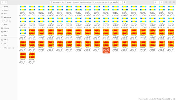
After producing thermal images manifesting stable and malfunctioning water-based HVAC system operations, I managed to construct a valid thermal image data set stored on the web application.
![]()
![]()
![]()
![]()
![]()
-
28Step 9: Building a neural network model (Audio MFE) w/ Edge Impulse Enterprise
As discussed earlier, while collecting audio samples to construct a valid audio data set, I simply differentiated the generated audio samples by the cooling fan failure presence:
- normal
- defective
After finalizing my audio data set, I started to work on my Audio MFE neural network model to identify anomalous sound emanating from the cooling fans.
Since Edge Impulse provides developer-friendly tools for advanced AI applications and supports almost every development board due to its model deployment options, I decided to utilize Edge Impulse Enterprise to build my Audio MFE neural network model. Also, Edge Impulse Enterprise incorporates state-of-the-art machine learning algorithms and scales them for edge devices such as XIAO ESP32C6.
For sound-based abnormality detection, Edge Impulse provides the required tools for inspecting audio samples, slicing them into smaller windows, and modifying windows to extract features from the supported audio file formats — WAV, MP4, etc.
Even though the Audio MFE processing block extracts time and frequency features from a signal, it employs a non-linear scale in the frequency domain, called Mel-scale. In that regard, the Audio MFE block extracts more features in the lower frequencies and fewer features in the high frequencies, thus it performs exceptionally well for non-voice recognition use cases.
Plausibly, Edge Impulse Enterprise allows building predictive models with enhanced machine learning algorithms optimized in size and precision and deploying the trained model as an Arduino library. Therefore, I was able to build an accurate Audio MFE neural network model to identify anomalous sound originating from the cooling fans and run the optimized model on XIAO ESP32C6 without any additional requirements.
You can inspect my Audio MFE neural network model on Edge Impulse as a public project.
-
29Step 9.1: Uploading and processing samples
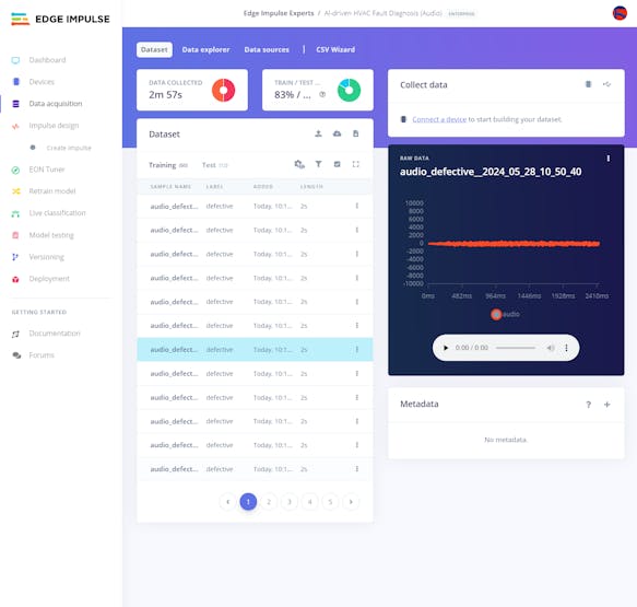
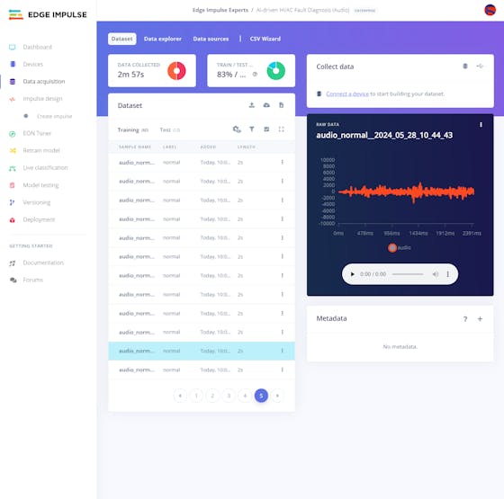
After splitting my audio data set into training and testing samples, I uploaded them to my project on Edge Impulse Enterprise.
#️⃣ First of all, to utilize the incorporated tools for advanced AI applications, sign up for Edge Impulse Enterprise.
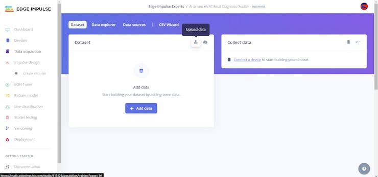
#️⃣ Then, create a new project under your organization.
![]()
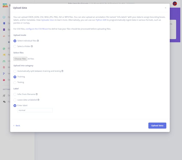
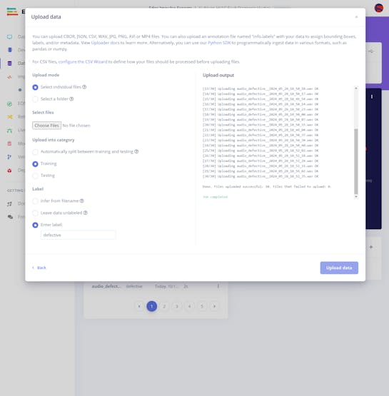
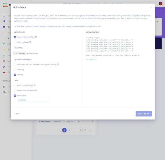
#️⃣ Navigate to the Data acquisition page and click the Upload data icon.
![]()
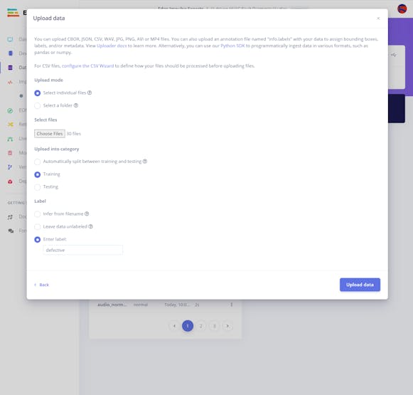
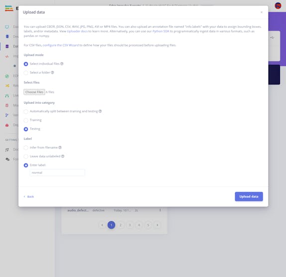
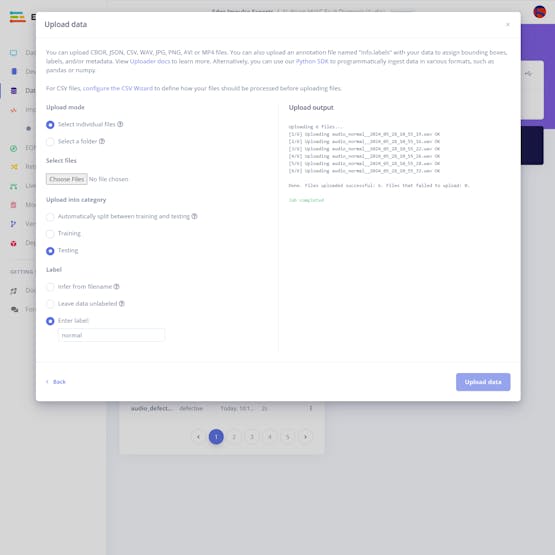
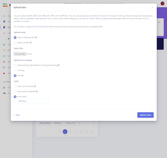
#️⃣ Choose the data category (training or testing) and select WAV audio files.
#️⃣ Utilize the Enter Label section to label the passed audio samples automatically with the same class in the file names.
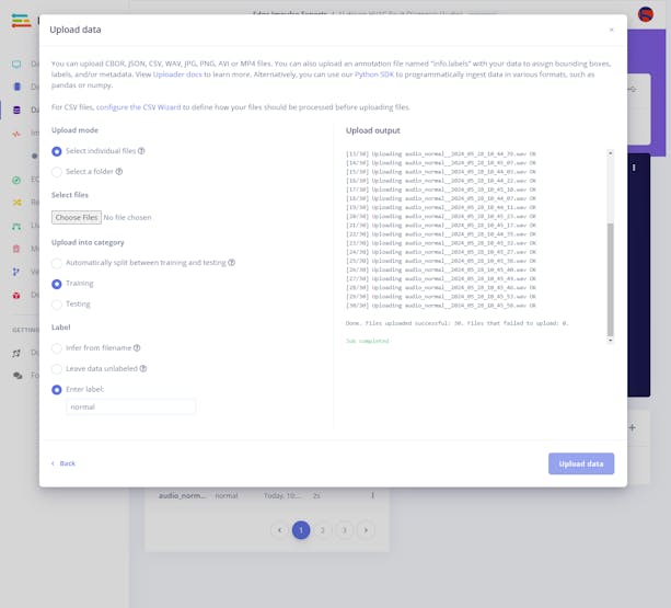
#️⃣ Then, click the Upload data button to upload the labeled audio samples.
![]()
![]()
![]()
![]()
![]()
![]()
![]()
![]()
![]()
![]()
-
30Step 9.2: Training the model on sound-based anomalous behavior
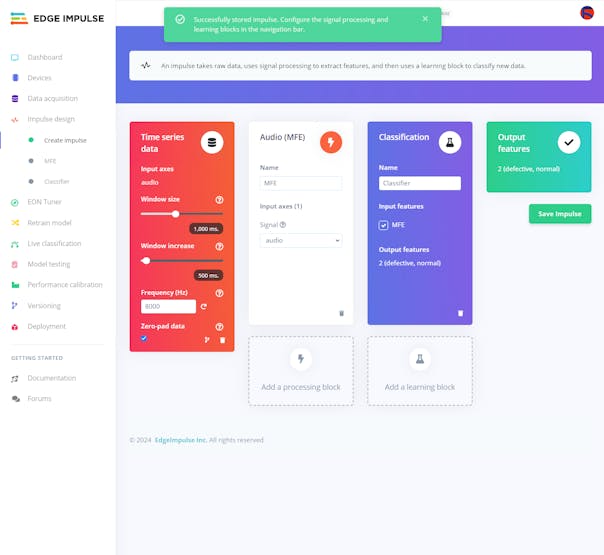
After uploading and labeling my training and testing samples successfully, I designed an impulse and trained the model to detect anomalous sound originating from the cooling fans of the water-based HVAC system.
An impulse is a custom machine learning model in Edge Impulse. I created my impulse by employing the Audio (MFE) processing block and the Classification learning block.
The Audio MFE processing block extracts time and frequency features from a signal and simplifies the generated features for non-voice recognition by using a non-linear scale — Mel-scale.
The Classification learning block represents a Keras neural network model. This learning block lets the user change the model settings, architecture, and layers.
#️⃣ Go to the Create impulse page and leave Window size and Window increase parameters as default. In this case, I did not need to slice the passed audio samples since all of them have roughly one-second duration.
![]()
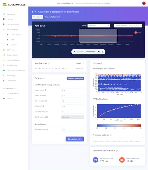
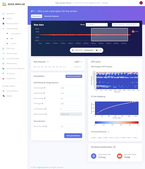
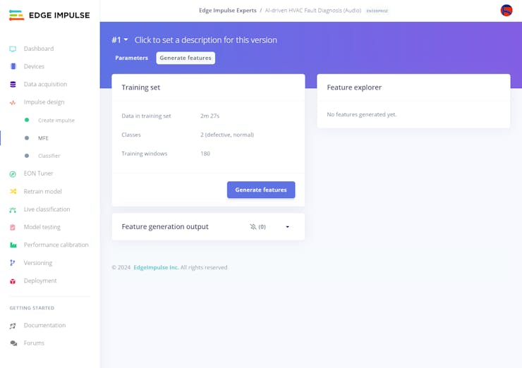
#️⃣ Before generating features for the Audio MFE model, go to the MFE page to configure the block settings if necessary.
#️⃣ Since the MFE block transforms a generated window into a table of data where each row represents a range of frequencies and each column represents a span of time, you can configure block parameters to adjust the frequency amplitude to change the MFE's output — spectrogram.
#️⃣ After inspecting the generated MFE parameters, I decided to utilize the default settings since my audio samples are simple and do not require precise tuning.
#️⃣ Click Save parameters to save the calculated MFE parameters.
![]()
![]()
![]()
![]()
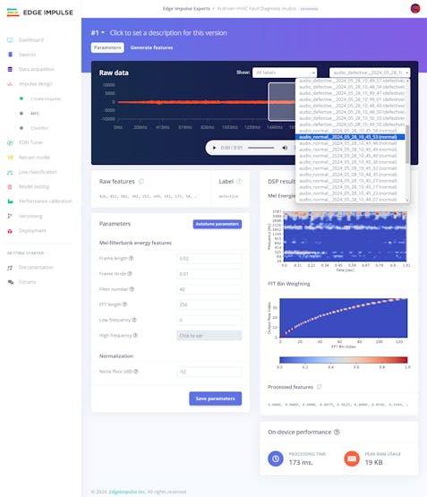
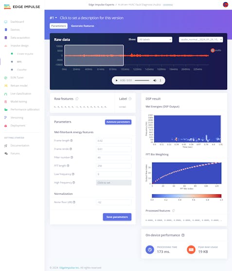
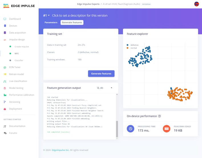
#️⃣ After saving parameters, click Generate features to apply the MFE signal processing block to training samples.
![]()
![]()
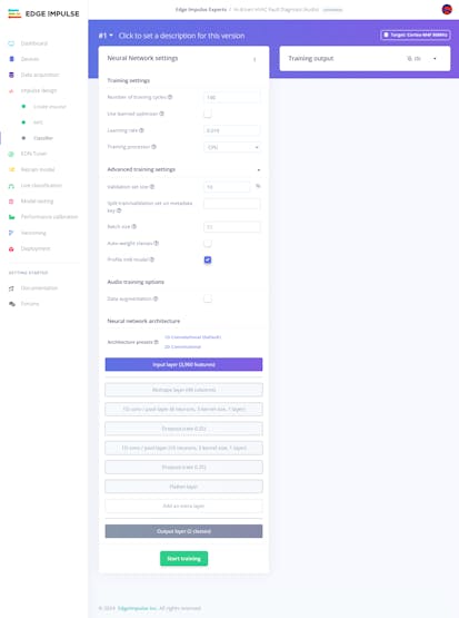
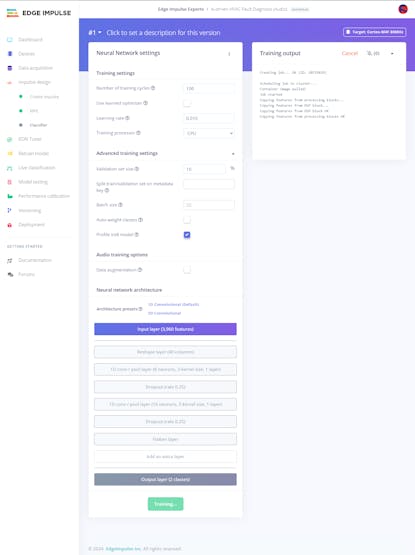
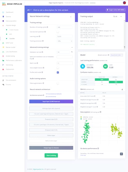
#️⃣ Finally, navigate to the Classifier page and click Start training.
![]()
![]()
According to my prolonged experiments, I modified the neural network settings and architecture to achieve reliable accuracy and validity:
📌 Neural network settings:
- Number of training cycles ➡ 100
- Learning rate ➡ 0.010
- Validation set size ➡ 10
After generating features and training my Audio MFE model, Edge Impulse evaluated the precision score (accuracy) as 100%.
Since I configured this neural network model to conform to the cooling fans of my simplified HVAC system, the precision score (accuracy) is approximately 100%. Thus, I highly recommend retraining the model before running inferences to detect anomalous sound emanating from different HVAC system components.
![]()
![]()
AI-driven Sound and Thermal HVAC Fault Diagnosis
Identify the faulty components via anomalous sound detection and diagnose ensuing cooling malfunctions via thermal visual anomaly detection.


Discussions
Become a Hackaday.io Member
Create an account to leave a comment. Already have an account? Log In.