Close
0%
0%

Putting 50 year old Motorola amplifier ICs to work

Using up more of my junk box

Similar projects worth following
Getting more practice in KiCad designing a PCB for a 50 year old IC

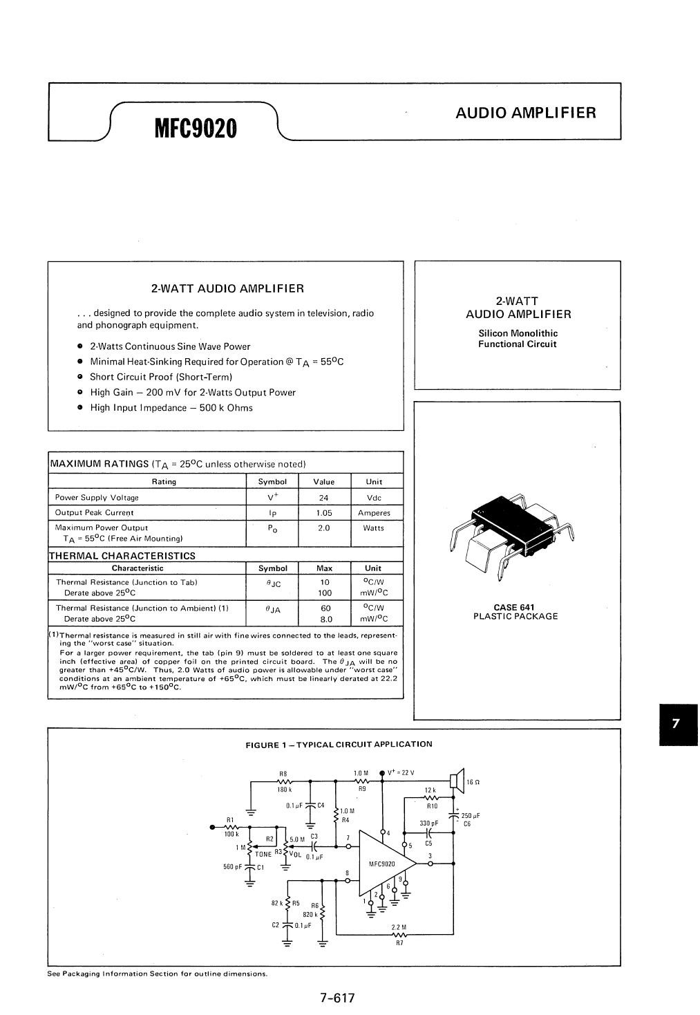
I found 4 of these MFC9020, never used, in my junkspares box. The datasheet appears in Motorola's 1972 edition of linear ICs so that makes them around 50 years old.

Since JLCPCB brought shipping down to $1.50 for 5 boards, boards cost $0.70 delivered. So I decided to put these ICs and a bunch of THT parts to work as 4 amplifiers and get practice in KiCad.

Details about this IC: This was designed before high current transistors were common in linear ICs, so they used higher voltages of up to 24V to get the needed output power. That also accounts for the 16 ohm speaker. This IC would have been used in car or table radios where the voltages are 12V upwards. Any accompanying digital display would have been VFD which also needs that order of voltage. However they could readily incorporate darlington pairs so the input and feedback pin impedances are high. There are a couple of tabs meant to be soldered onto the PCB copper to help dissipate heat.

The one of a kind package gave me practice creating a footprint in KiCad. The pin spacings I obtained from the datasheet. I needed a slot for the cooling tab. Slots have to be 2 mm or larger and have rounded ends due to the cutting tool. I also had to remove the soldermask around the slot to provide a pad to solder the tab to.

My schematic is just a copy of the reference schematic without the volume and tone control pots at the input and with added bypass capacitor C1, and load resistor R11 to ensure that the driver transistor has current even without a speaker connected.

I picked yellow soldermask for novelty. Generally I prefer blue or green. After the board was sent off for fabrication I realised that I should have put silkscreen legends on the input, speaker, and power ports. But no matter, this is a once-only design for myself only.

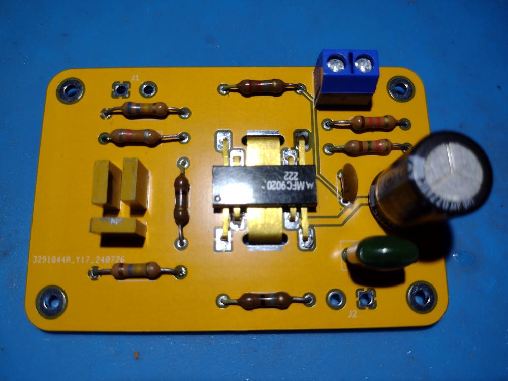
Here's a picture of an assembled board. The yellow has an orange tint but attractively different from the usual green.
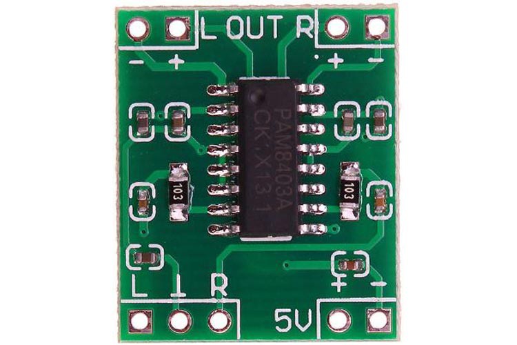
For comparison here's a modern dual-channel class D amplifier, much smaller and hardly any heat generation due to class D. Some chips even have a bluetooth receiver on-chip, something that didn't exist 50 years ago.
  • Using a hacksaw as a hacking tool, literally

    Ken Yap09/21/2024 at 06:27 0 comments

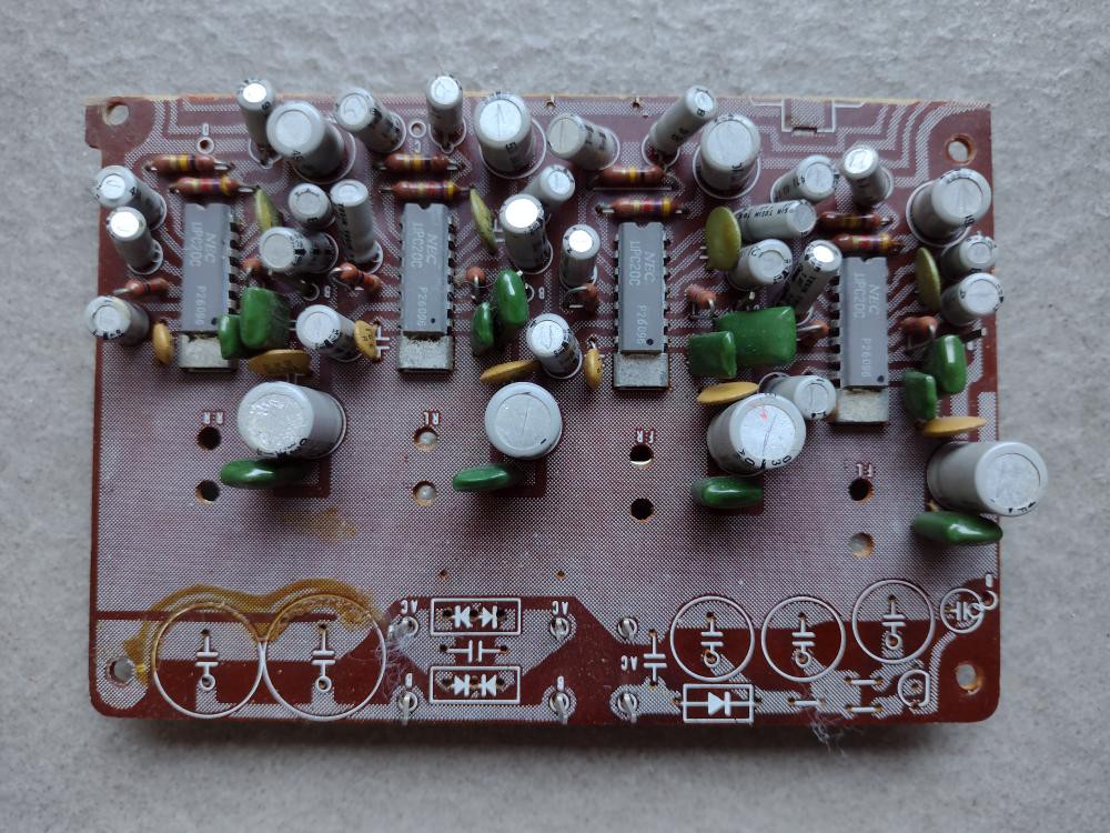
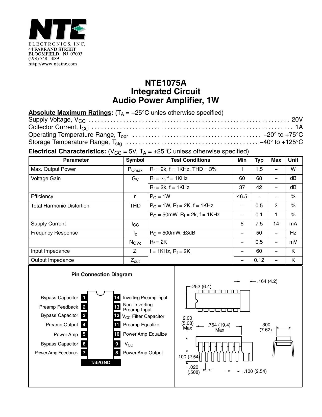
    I found another batch of half-century old ICs. These were from the quadraphonic amp that I hacked in A fugly amplifier. The NEC uPC20C power amplifier chips are from around 1973. According to its datasheet, it runs at 20V and produces 1.5W into 8 ohm speakers. The heatsink tabs are at the end of the 14 pin DIP package. (The datasheet labels it NTE1075A, a second-source equivalent.)

    I could find only one schematic on the Internet and it comes from the book 5000 Power IC Amplifiers. Other instances are copies of this schematic. So I decided to reverse engineer the circuit on the board, and in the process discovered some errors in the schematic, mostly in the polarity of the electrolytic capacitors, which I have corrected. Some component values were also changed. It's interesting that NEC tried to minimise the external resistors required but required many bypass and compensation capacitors.

    At first I thought I could desolder the chips from the board and put on a newly designed board, using the same attractive yellow soldermask as for the Motorola MFC9020 ICs. I got as far as creating a new symbol and a new footprint for the IC, including the heatsink tabs, drawing the schematic, and laying out the board. But since I'm the paragon of laziness, I realised that I could reuse the old board by hacksawing off the quadraphonic processing part. It didn't take too long as the board is phenolic rather than the tougher fibreglass. The result is shown above. So this is why this write-up is just a log on an existing project, as it's not enough effort to justify a new project. Notice that the top silkscreen echoes the bottom copper traces which helps reverse engineering.

    I've removed the bridge rectifier and smoothing capacitors from the board as I will probably use a 5V to 20V boost SMPS if I get a round tuit and deploy this board.

View project log

Enjoy this project?

Share

Discussions

Dan Julio wrote 08/12/2024 at 16:06 point

Awesome IC package.  But inquiring minds want to know...how does it sound? :-)

  Are you sure? yes | no

Ken Yap wrote 08/12/2024 at 22:25 point

I'll have to get a round tuit wiring to speakers. :)

  Are you sure? yes | no

420pootang69 wrote 08/10/2024 at 09:55 point

A whole 2 watts!

  Are you sure? yes | no

Similar Projects

Does this project spark your interest?

Become a member to follow this project and never miss any updates