 Andy Geppert
-
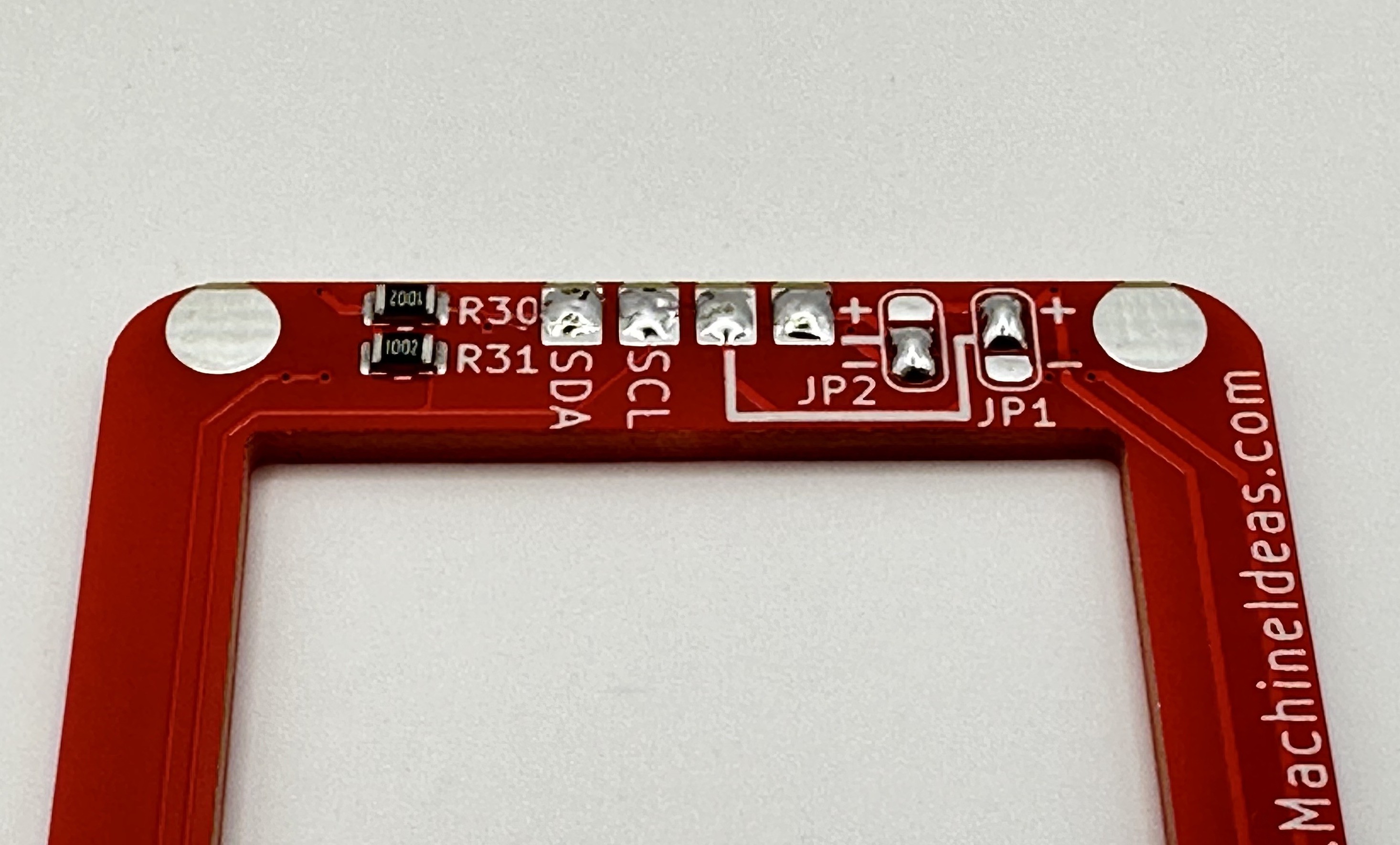
1OLED Power Solder Jumper Setting and Pad Prep
On the bottom side of the board, there are two solder jumpers that need to be configured for the OLED panel you are using. Some panels come with the GND and 3V3 positions reversed, so these are left open for you to configure to match the OLED board you have. You can also pre-tin the four OLED pads to make them easier to solder to in the final step. See the photo below:
![]()
JP2 selects whether the outermost OLED pin is 3V3 or GND. JP1 selects the inner pin polarity. The configuration shown above seems to be
-
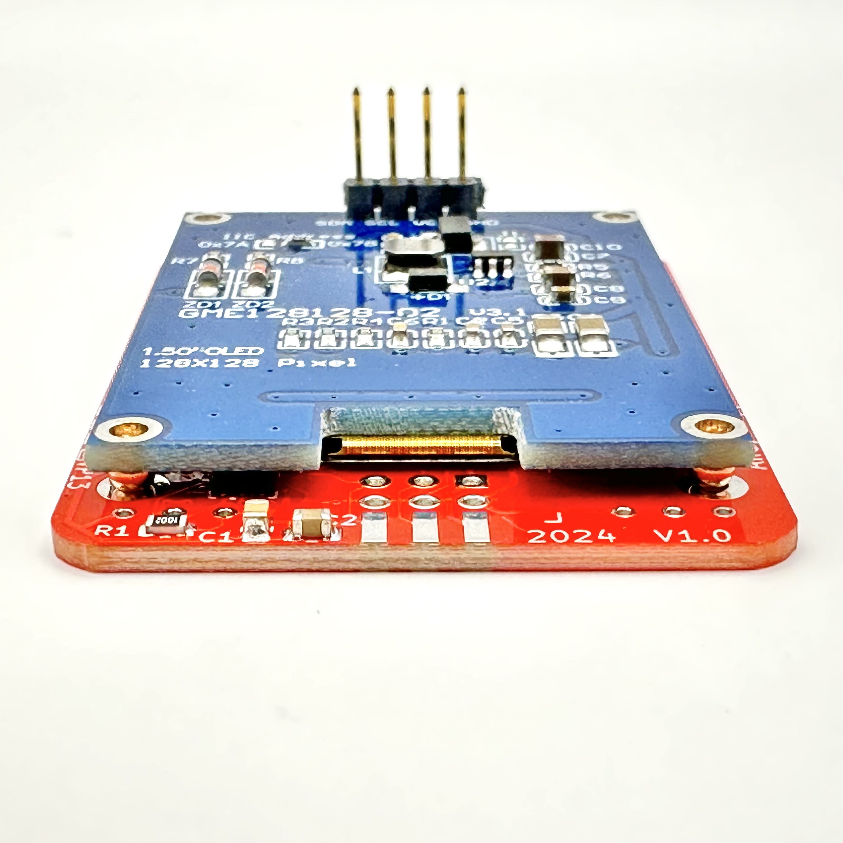
2OLED Alignment Spheres
Solder the two 2.5mm copper spheres into the large round through-hole pads near the bottom edge of the board, on the back side. You can solder them from the side with the spheres, or flip the board right-side-up on a silicone matt, and solder the sphere into position, through the hole, from the front side. The final result you are going for:
![]()
-
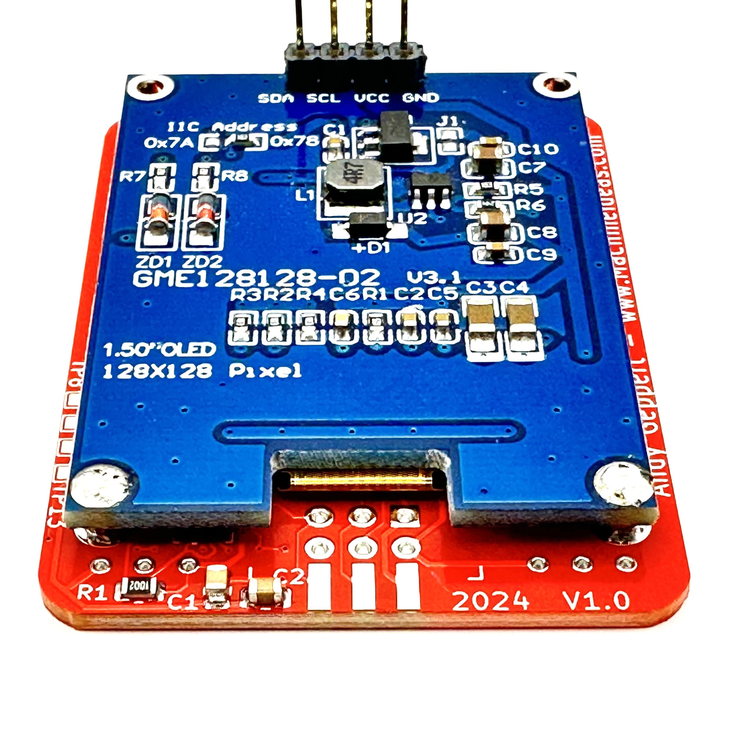
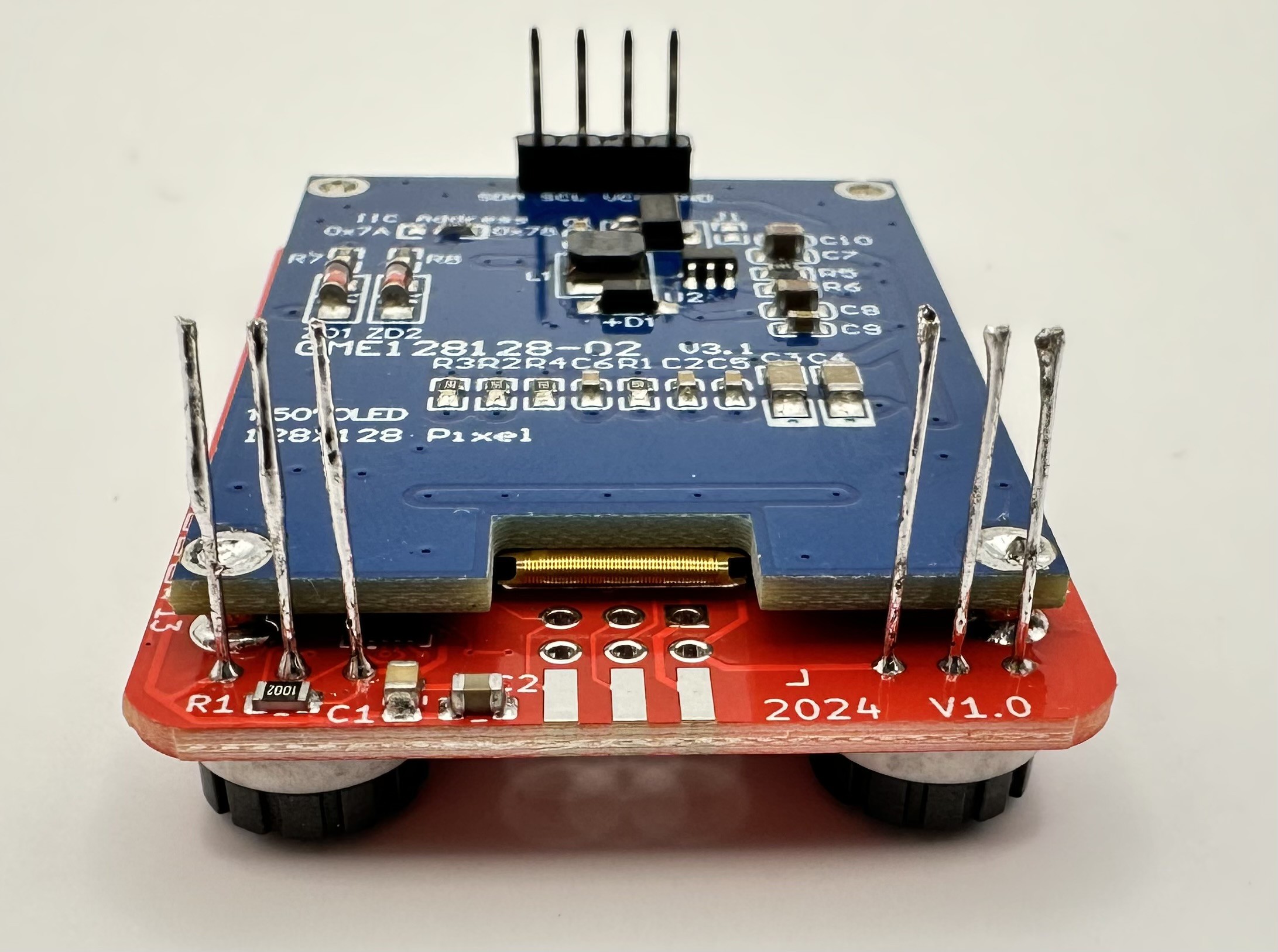
3Install OLED Board and secure to bottom edge
Place the OLED board down on the back side of the Etch sAo Sketch PCB, and align the bottom holes of over the spheres. Gently hold the two PCBs together like a sandwich, and solder through the open OLED board holes onto the copper spheres.
Before soldering:
![]()
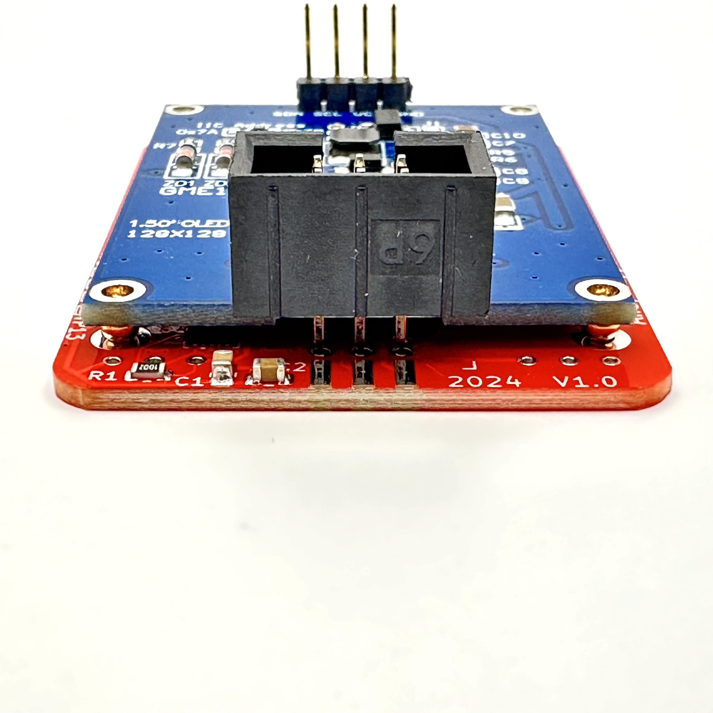
After soldering:
![]()
-
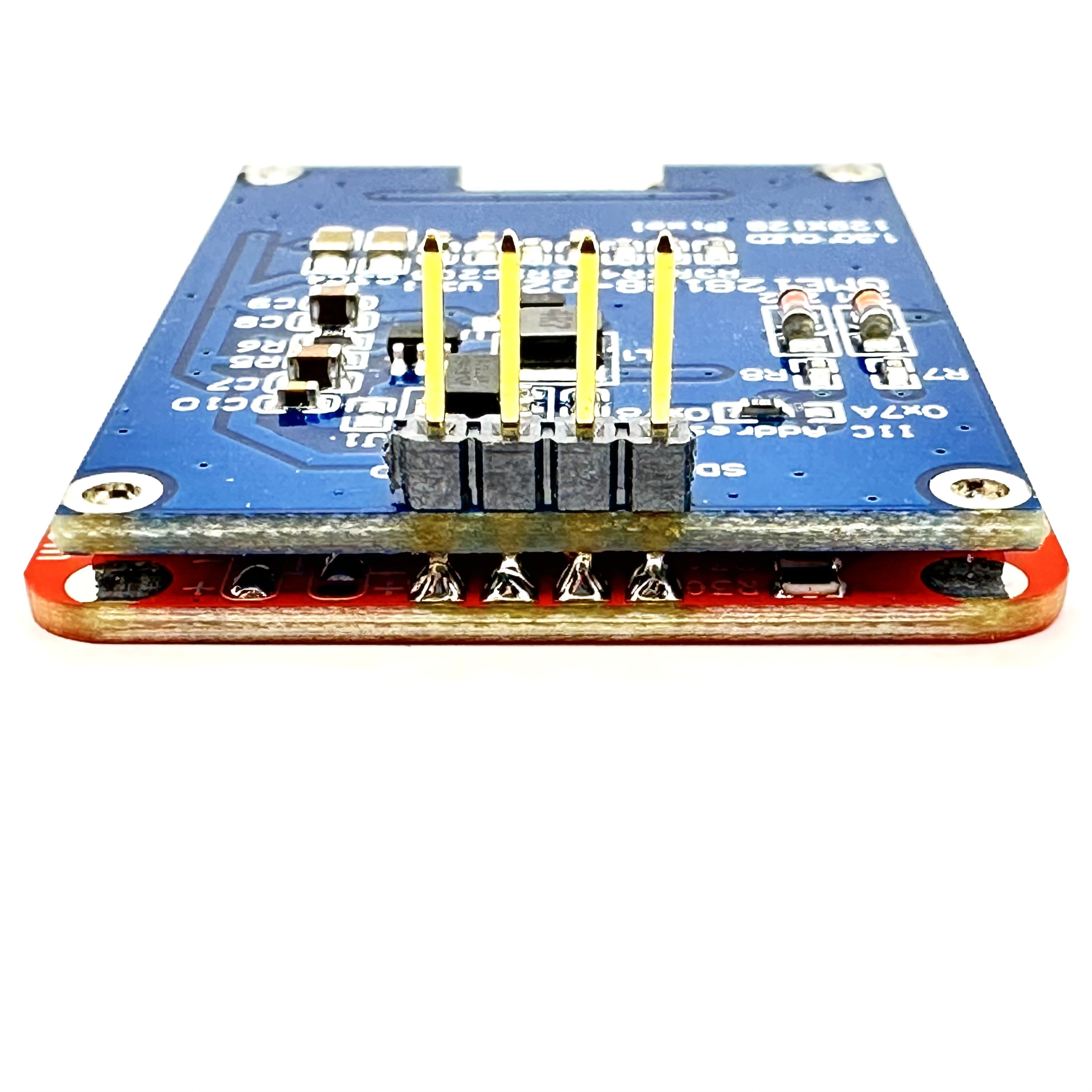
4Secure OLED board to bottom edge
Carefully turn the board around. Gently squeeze it while re-heating the solder applied from the first step to each of the four pins:
![]()
There is no need to secure the outer corners, but you can trim the extended OLED 4-pin header down and use those bits of metal to secure the outer corners if you want to.
-
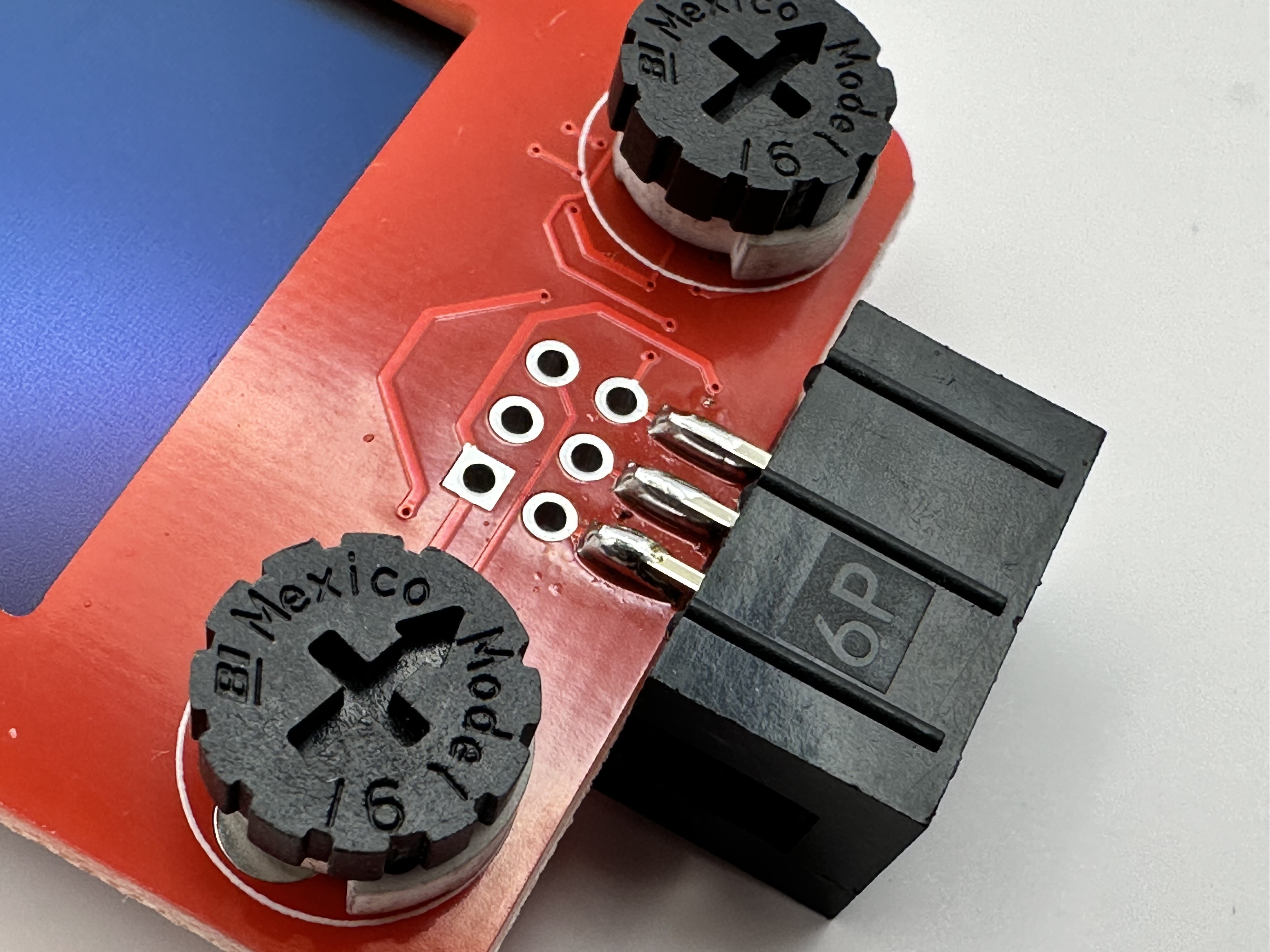
5Install the Potentiometers
Insert the potentiometers through the front side:
![]()
Trim the wires flush on the bottom side of the board and solder them all in place.
![]()
-
6SAO Shrouded Header Installation - Two Options
The SAO header pins aren't quite long enough to reach the PCB with the OLED board in place. With a small blunt metal tool, you can gently push the pins through the socket a little bit (1mm or 1/16 inch) so they can make contact with the red PCB holes. Note that socket notch is up, toward the inside of the PCB.
![]()
You also have the option to use the header as is, but mount it to the bottom edge of the PCB. In this case the notch needs to be DOWN away from the viewing side.
![]()
-
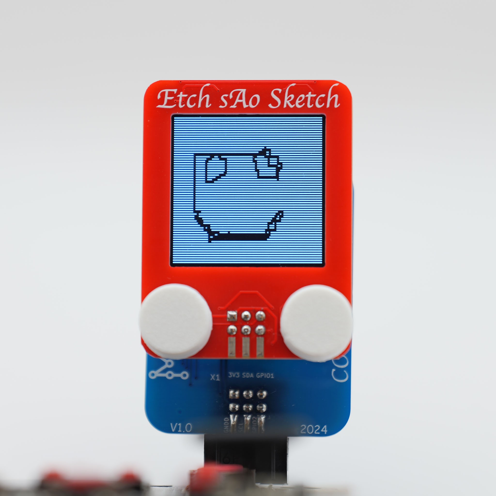
7Install the caps
Press on the white knob caps.
![]()
-
8Write some code
There is demo code available here for basic drawing and the "turn over and shake left-right to clear" feature:
https://github.com/ageppert/SAO_Etch_sAo_Sketch
The 128x128 Grayscale OLED is being controlled with an SSD1327 at 0x3C. You can use the Adafruit SSD1327 library (and friends) and learn more about this type of display here:
https://learn.adafruit.com/adafruit-grayscale-1-5-128x128-oled-display/arduino-wiring-and-test
The Accelerometer is an LIS3DH at 0x19. The demo code uses the Adafruit LIS3DH Library. Learn more:
https://learn.sparkfun.com/tutorials/lis3dh-hookup-guide
https://learn.adafruit.com/adafruit-lis3dh-triple-axis-accelerometer-breakout/arduino
Discussions
Become a Hackaday.io Member
Create an account to leave a comment. Already have an account? Log In.