Andy Geppert
-
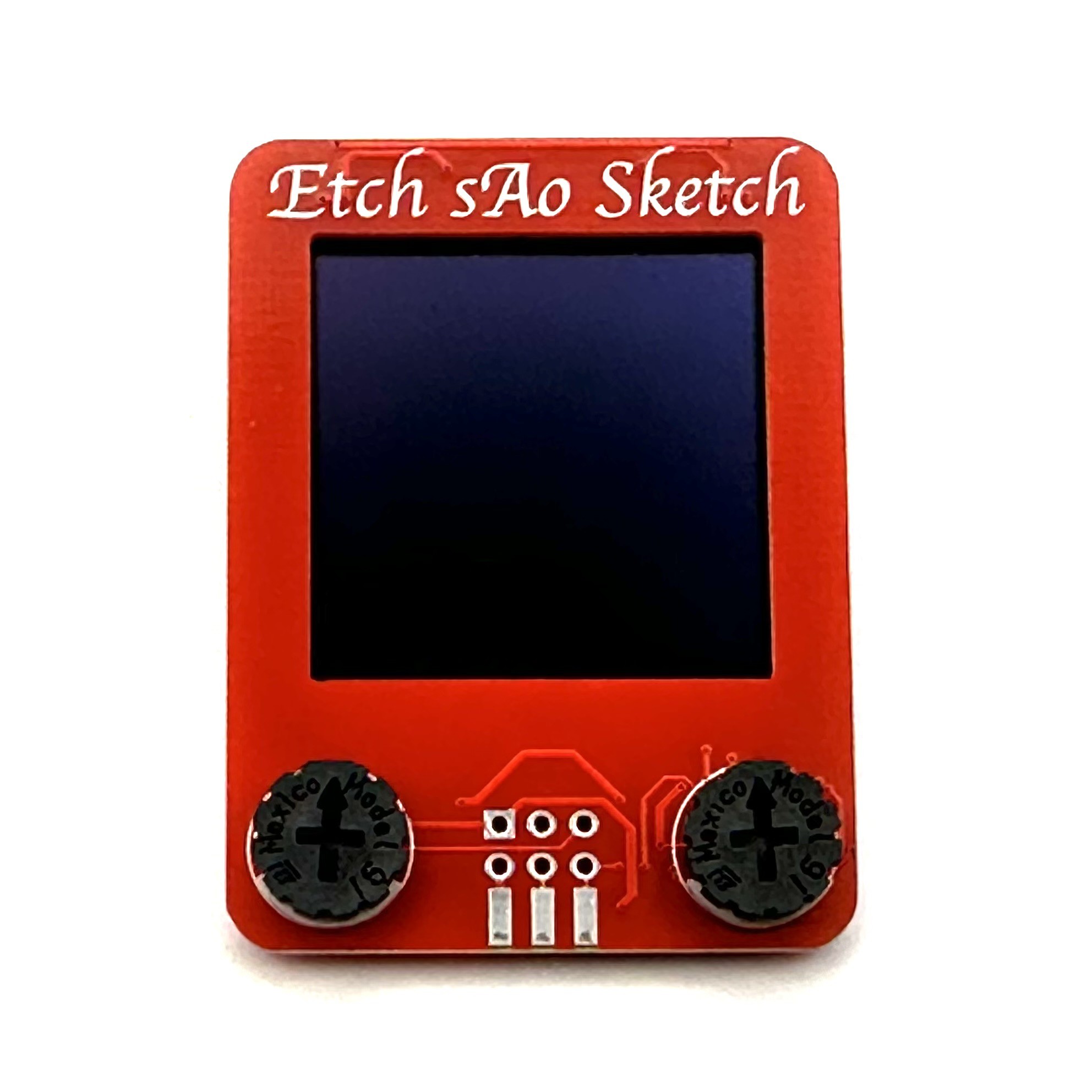
Etch sAo Sketch is alive a well!
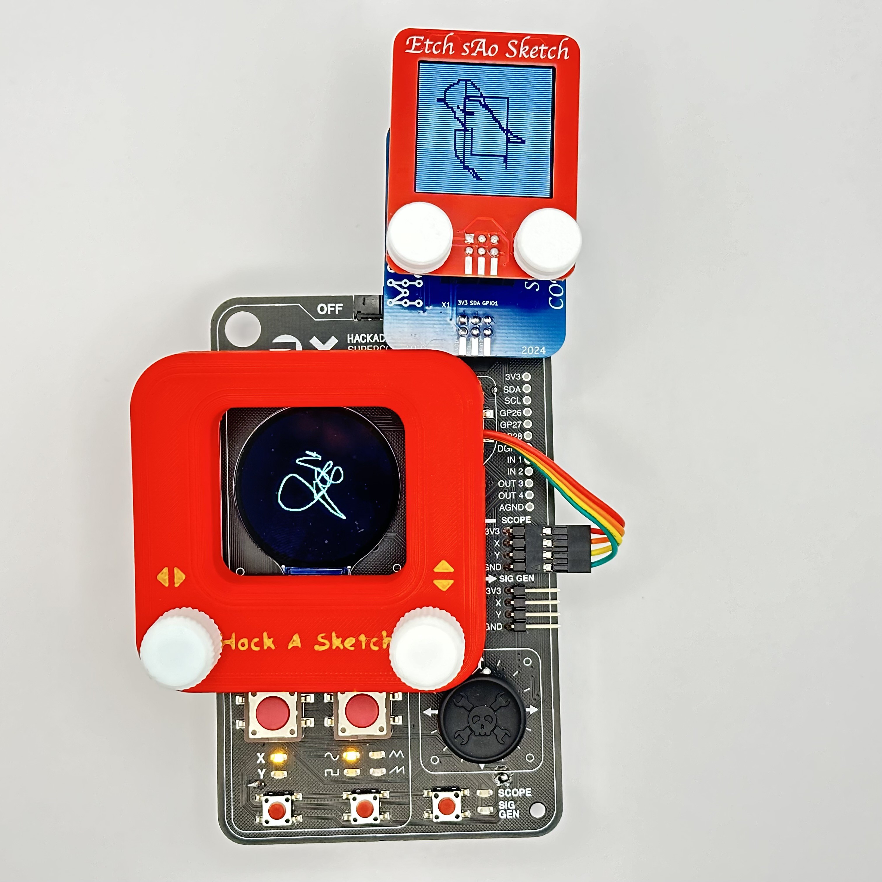
10/11/2024 at 20:35 • 0 commentsIt's working!!!

This prototype turned out extremely well. I'm very happy with it. The components went together smoothly, with only a minor (trimmable) interference between the SAO header and an adjacent resistor on the back side. The pots work surprisingly well and have just enough travel to provide fine control over the dot, and have good friction.
Gotta finish up the documentation next!
-
Bring-up, first curve ball...
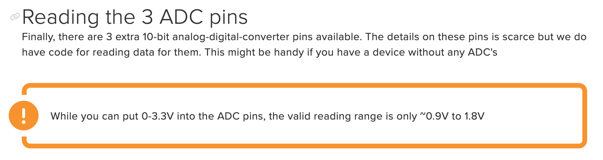
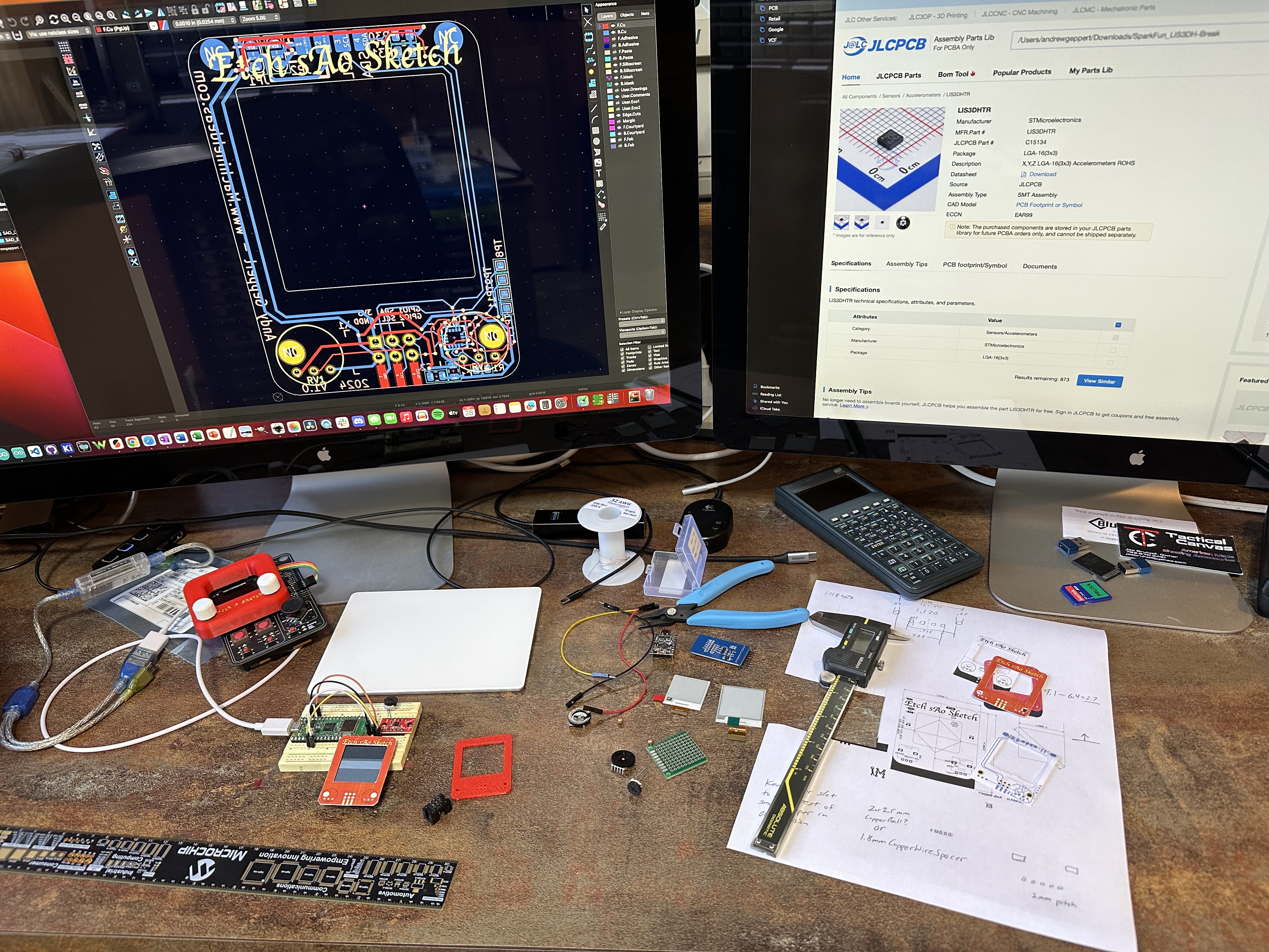
10/10/2024 at 05:04 • 0 commentsWell, this is the first time I've used an ADC that didn't offer 0 to 3.3V range. I didn't look closely at the LIS3DH accelerometer data sheet until I started testing the boards.
Thank you for clearing this up, Adafruit team!
https://learn.adafruit.com/adafruit-lis3dh-triple-axis-accelerometer-breakout/arduino
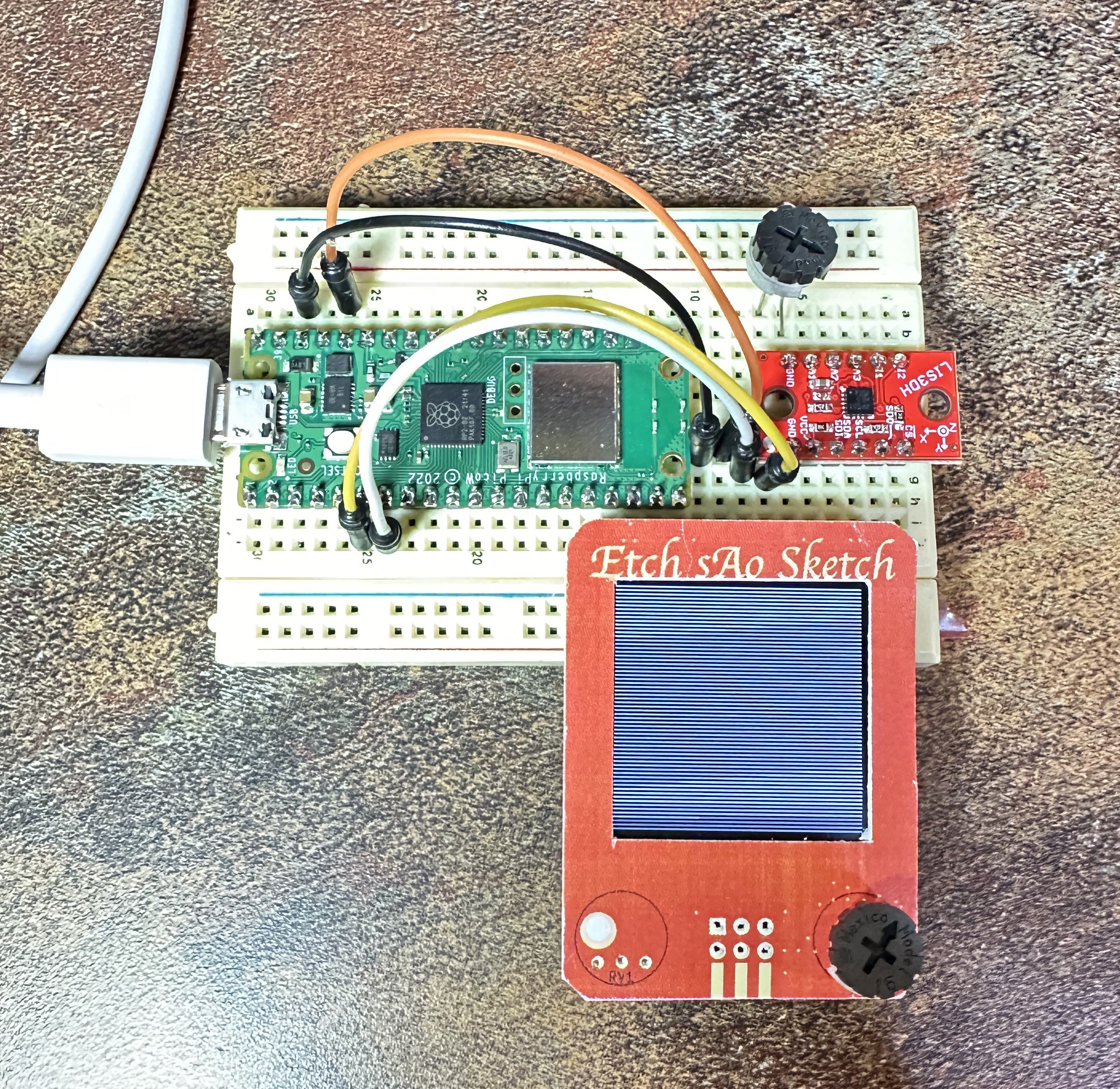
Good thing I wired those pots to GPIO1 and 2 of the SAO port!But the good news is that all of the hardware works! I'm excited to see what possibilities are unleashed with the 3-axis accelerometer as part of the user interface.
-
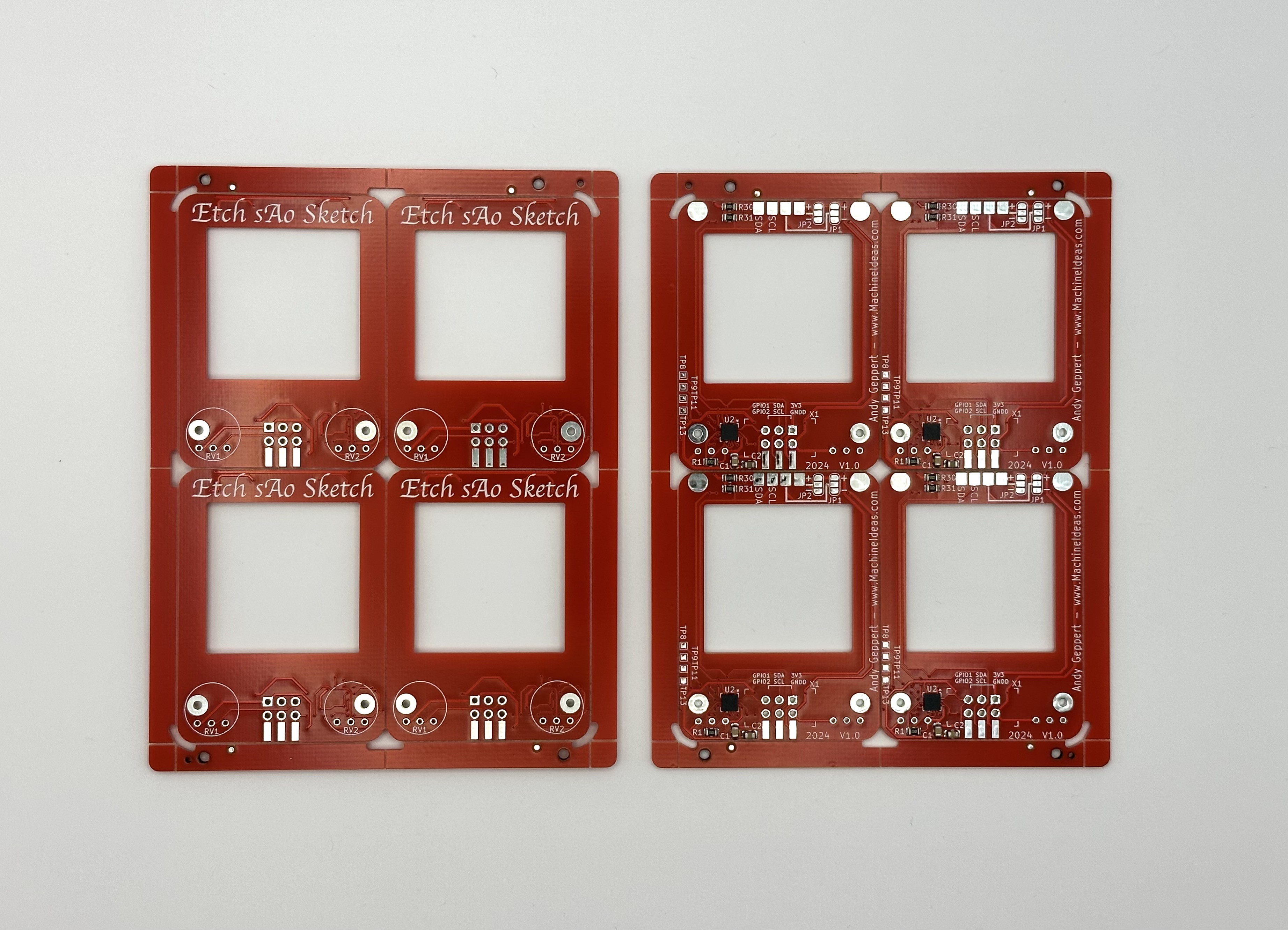
Boards arrived! Let the bring-up begin!
10/10/2024 at 04:55 • 2 commentsOh yeah, these look good!
Here are the copper alignment balls in position:
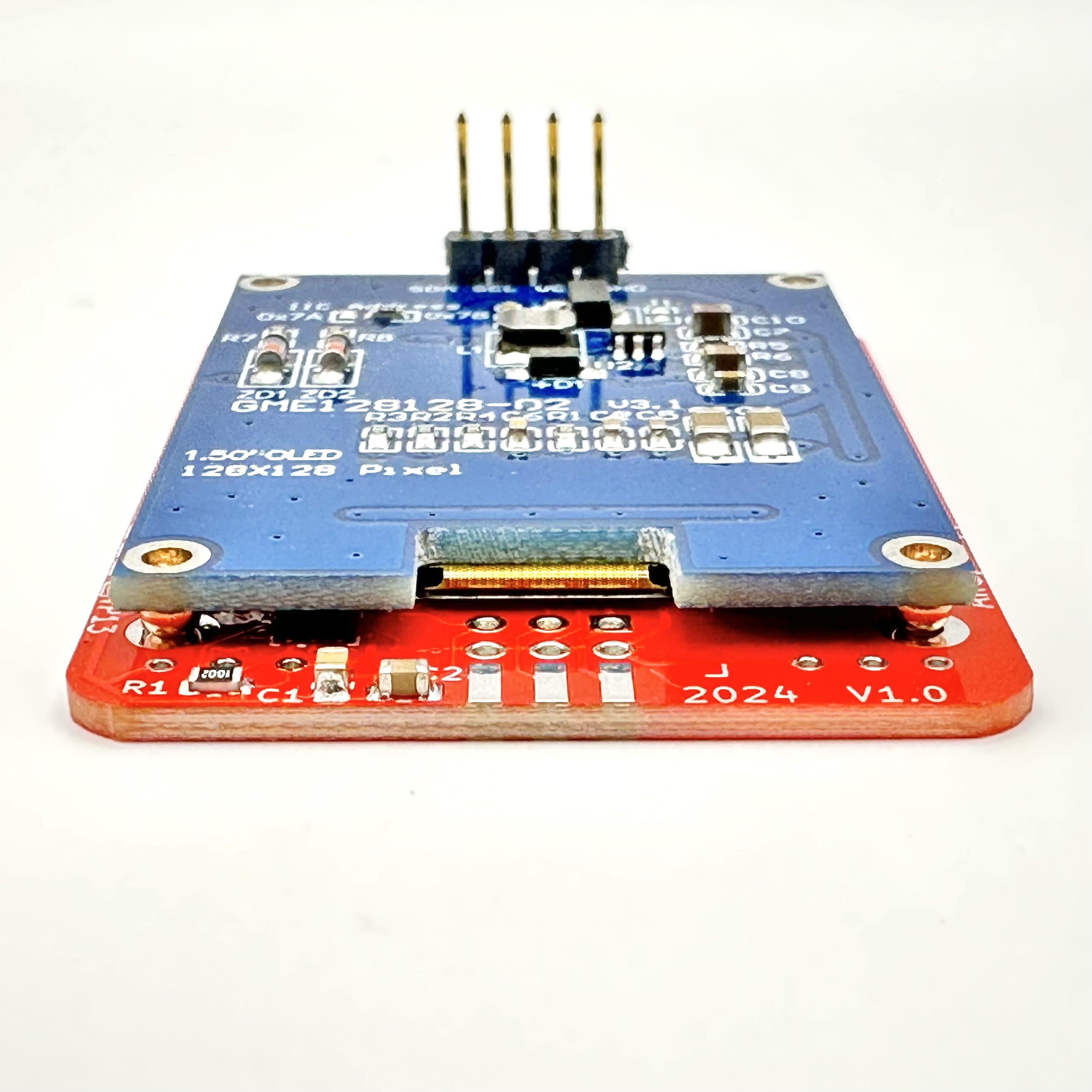
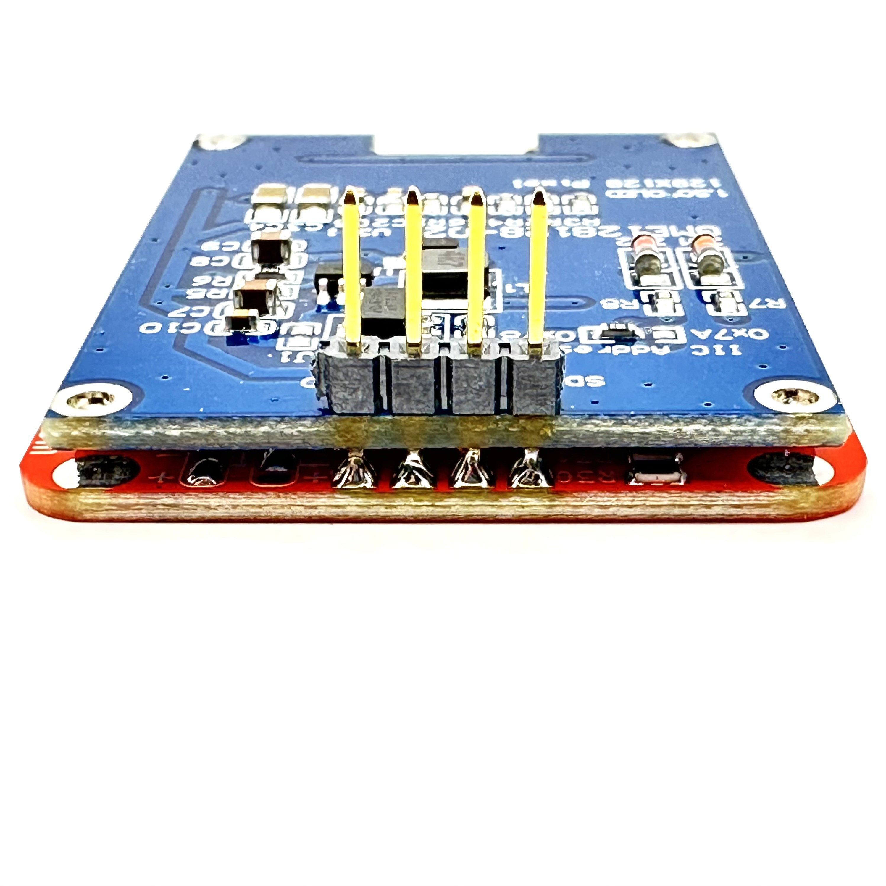
With a gentle pressure between the two boards, the spheres nestle into the holes in the boards and provide alignment between them. They are soldering in place and secure the bottom edge of the boards together:
And final soldered of the OLED header pins on the top edge, to connect and secure the other end:
And now for some potentiometers:
Then apply the proper knobs:
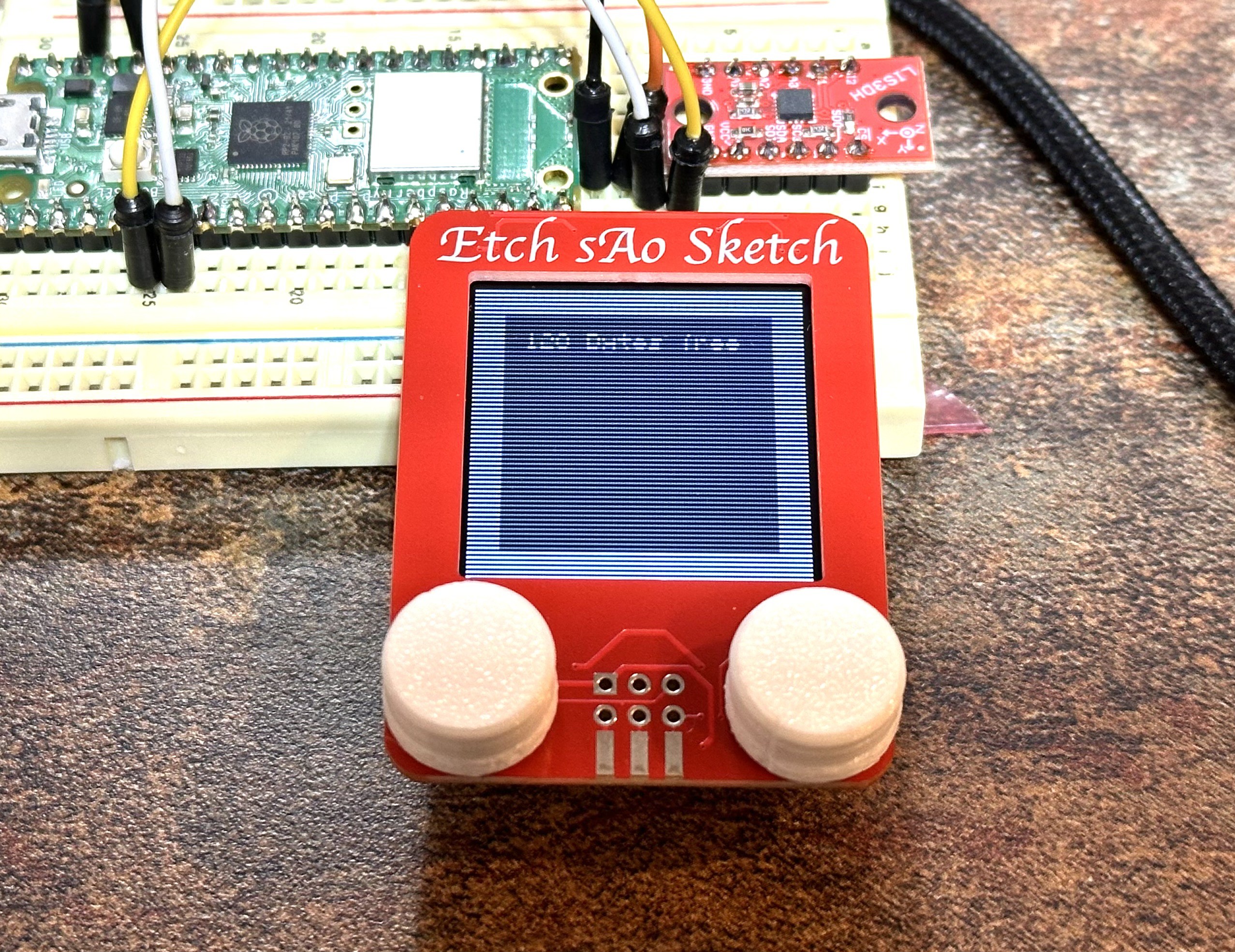
Now it's time for some coding and testing. I ran example code for the OLED and Accelerometer and it worked! In the photo, I'm only connect to the SAO via the four pins that are also anchored to the OLED display.
Next, I need to tie it all together and get the user interface "just right." Including the accelerometers!
-
Design Ideas and Compromises
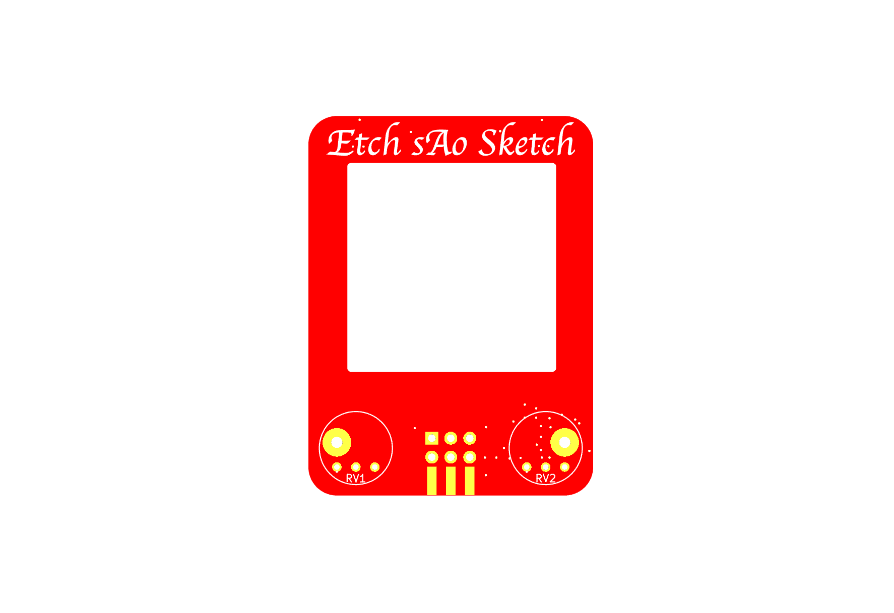
10/09/2024 at 01:25 • 0 commentsThe two big constraints for this design are the size and the desire to keep everything on the I2C bus for the sake of easy access with an SAO port. I think I've pulled together a design that offers the right mix of capabilities and holding up the design expectations with something called Etch sAo Sketch. Here is the V1 design, as released for prototyping.
Also the trick used by [Aaron] in the Macintosh SAO, where the OLED header pins are solder to surface mount pads on the bottom of the board. I also wanted to deploy another trick, using "tooling balls" which I'll share more on later, to align and secure the OLED board to the bottom of my board.
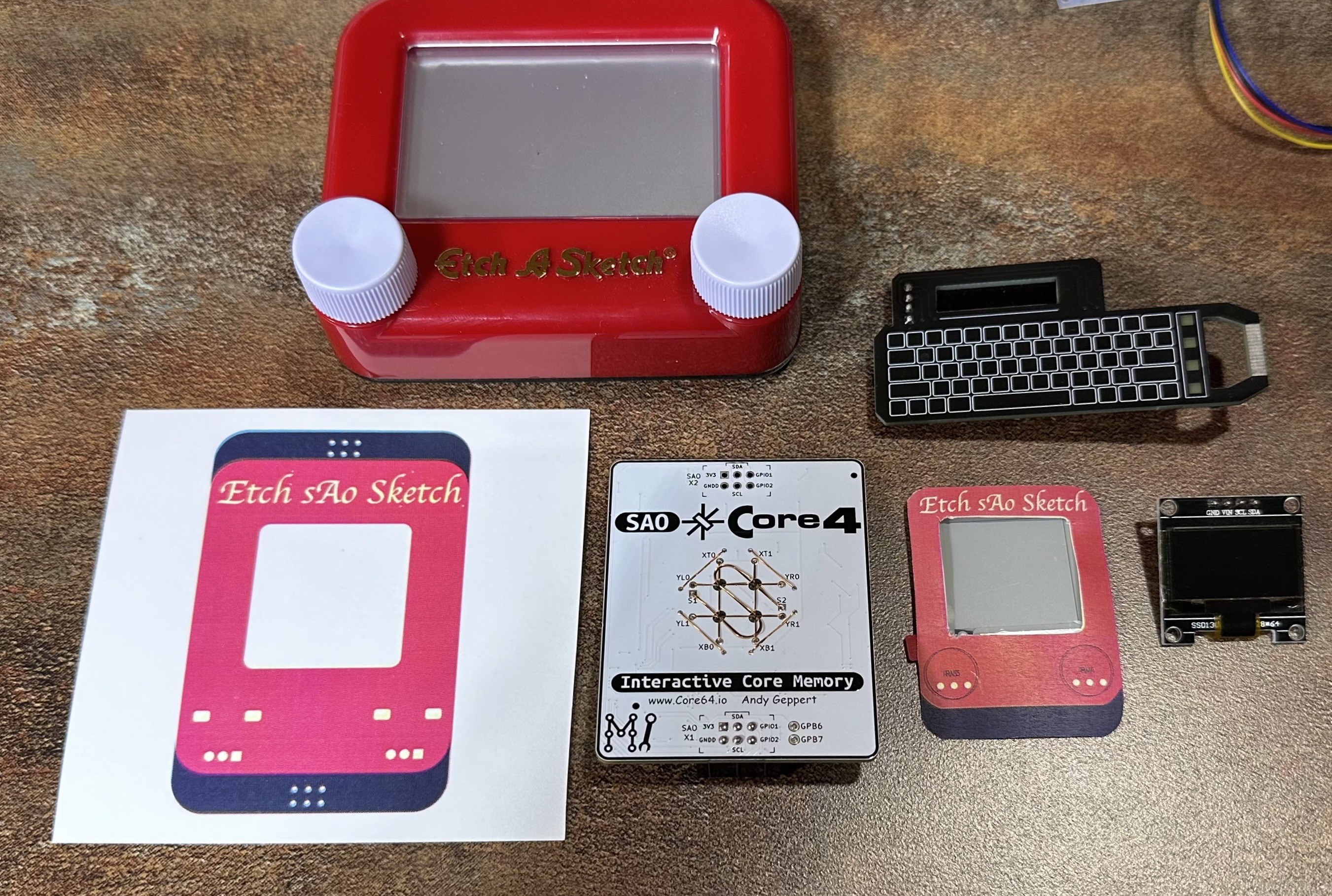
After a several rounds of designing, compromising, component selection, making paper and 3D-printed templates...
I finally settled on a 1.5" OLED screen and potentiometers that just barely fit, and a LIS3DH accelerometer (with analog inputs for the pots!). This means all aspects of the SAO can be controlled with the I2C bus. Here is a proof of concept:
Bonus: these are gray scale capable OLED screens which I'm looking forward to making use of. Here are renders of the board design:
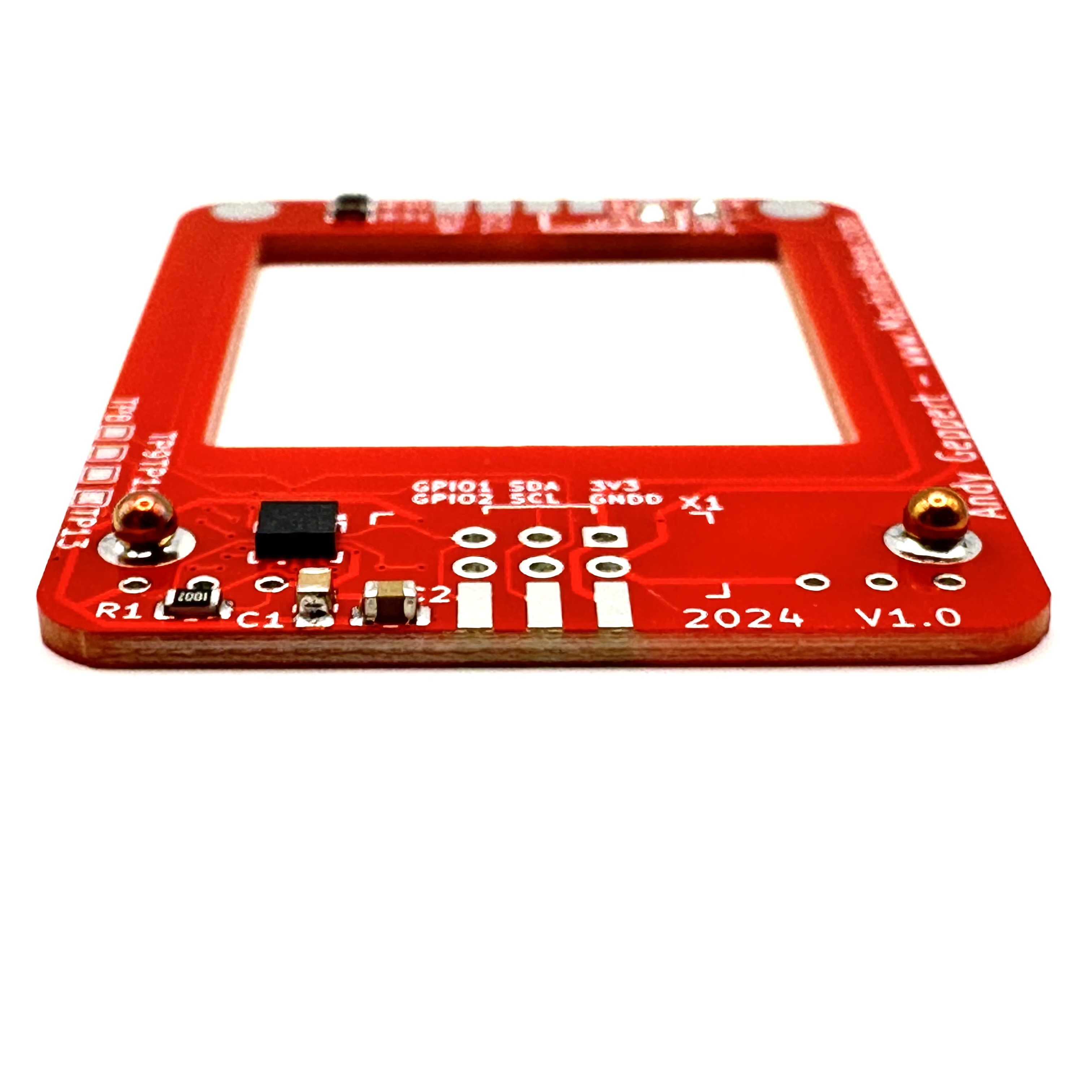
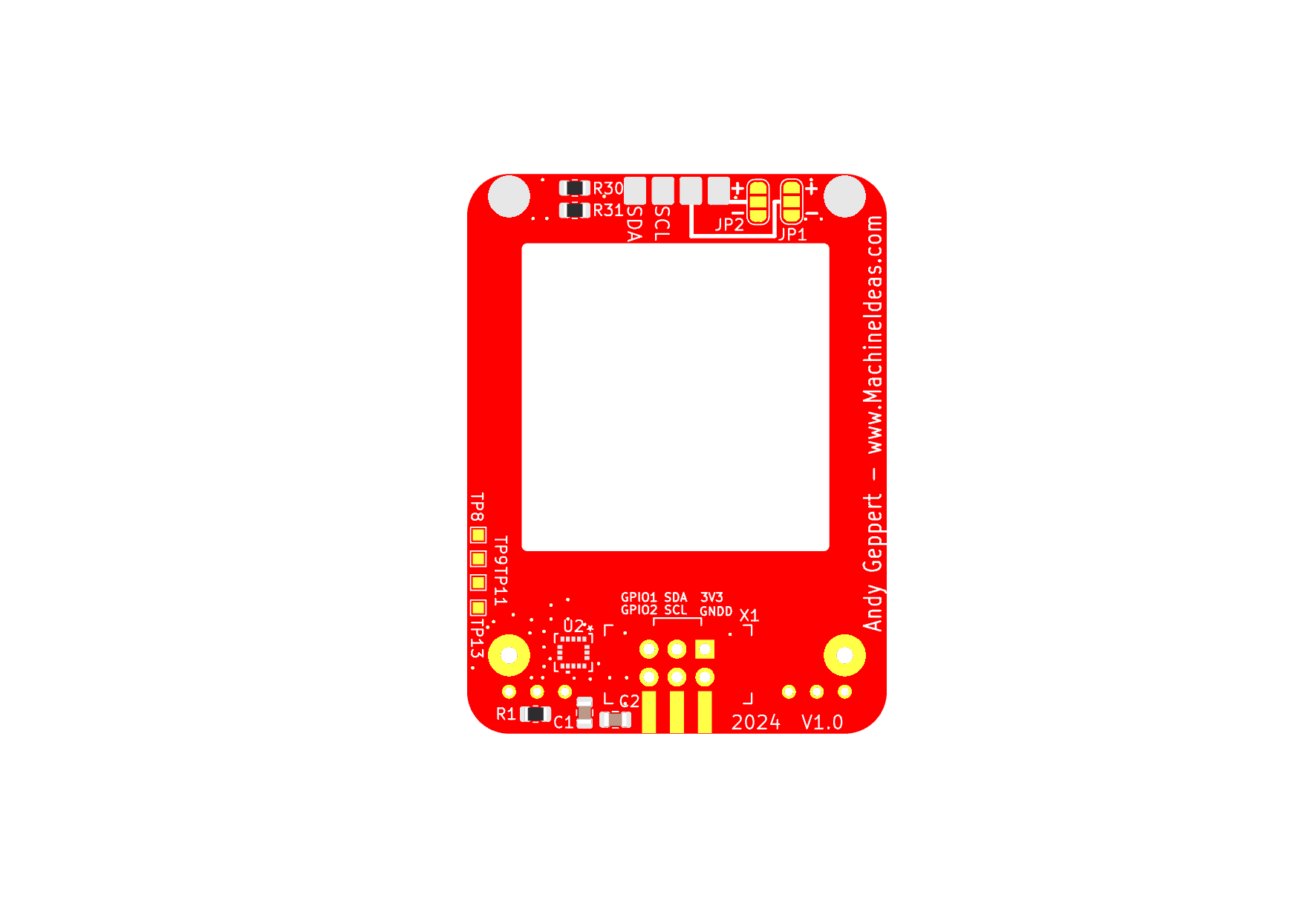
Back side with the accelerometer and associated components tucked into a gap between the OLED board, the main board here, the potentiometer, and the SAO socket:
Those big yellow plated-through-holes at the bottom will be used for the tooling ball concept.
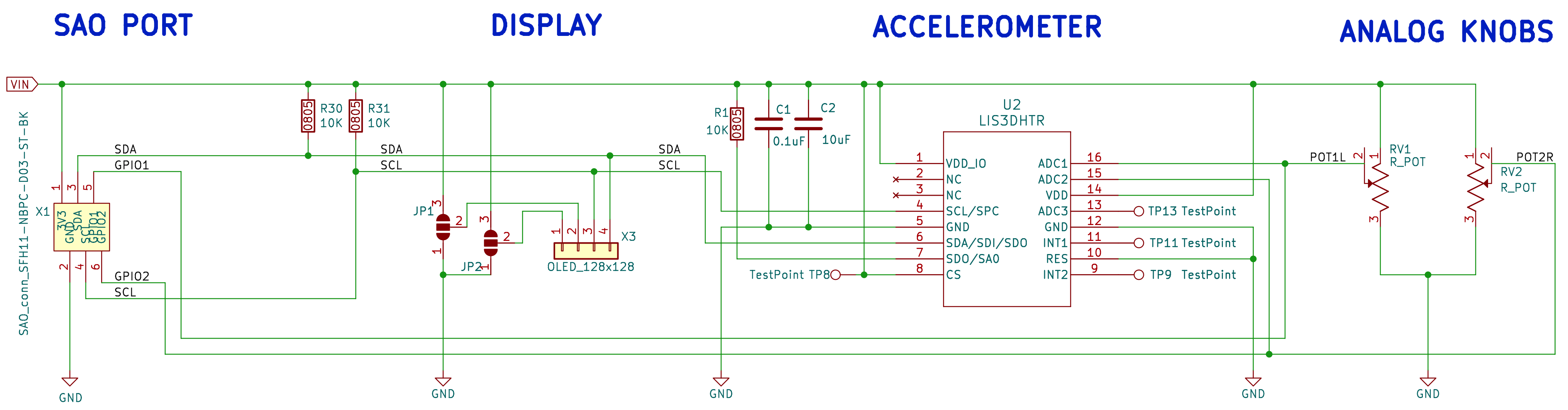
The schematic is relatively simple. SAO Port -> Display -> Accelerometer -> Two Analog Pots. The potentiometer outputs are tied to the GPIO 1 and 2 pins of the SAO port, and into the analog inputs of the accelerometer.
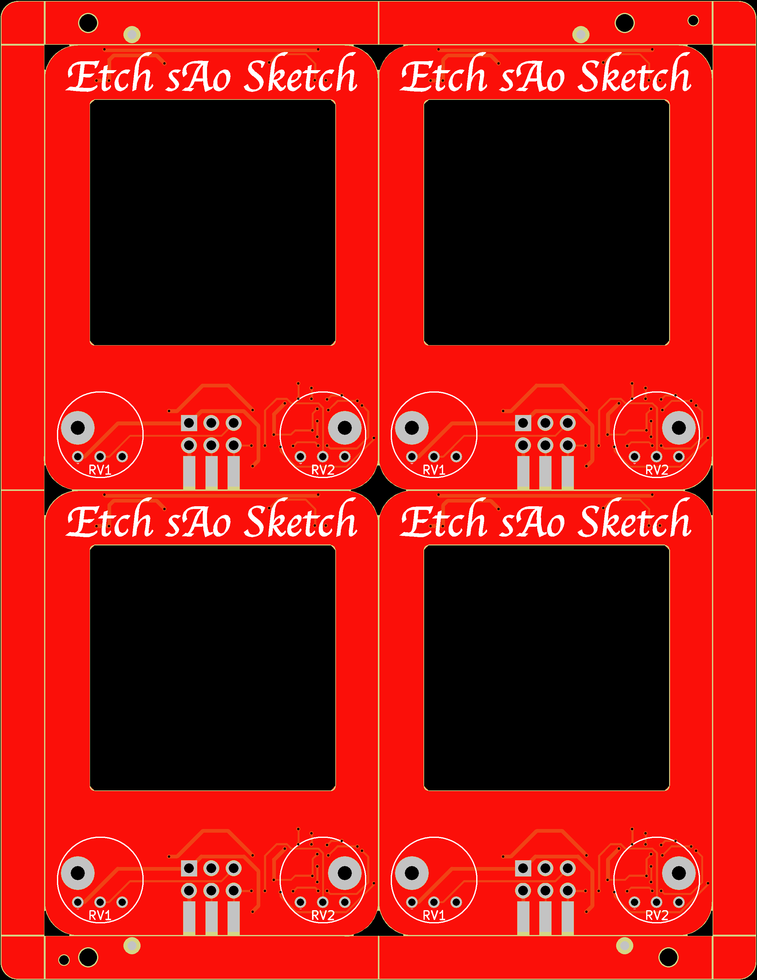
And now it's time to release it for the first round of prototypes. I'm committing to a small batch with the SMD assembly included, and will use the panelization services of JLCPCB to keep the final parts free of fiducials and tooling holes.
I've set aside the ePaper version for now to focus on the OLED version. But the ePaper screen I choose should fit, and with some hacking, I think I can make a proof-of-concept for that version after I get this version going.
Next post should be with parts in hand, and ready to bring-up!
-
Architecture Options
09/18/2024 at 14:06 • 4 commentsAfter a wide survey of options, I think there are two architectures that standout for this project. The first one meets the MUST HAVE requirements and the second one exceeds the NICE TO HAVE requirements with significant benefits and capabilities. I welcome feedback and discussion on this fork in the road!
ARCHITECTURE V1 (OLED with I2C simplicity):
- Display is OLED with I2C control directly via SAO I2C lines.
- The two knobs are analog pots, each connected to GPIO 1 and 2 of the SAO port.
- Accelerometer is connected to the SAO I2C lines.
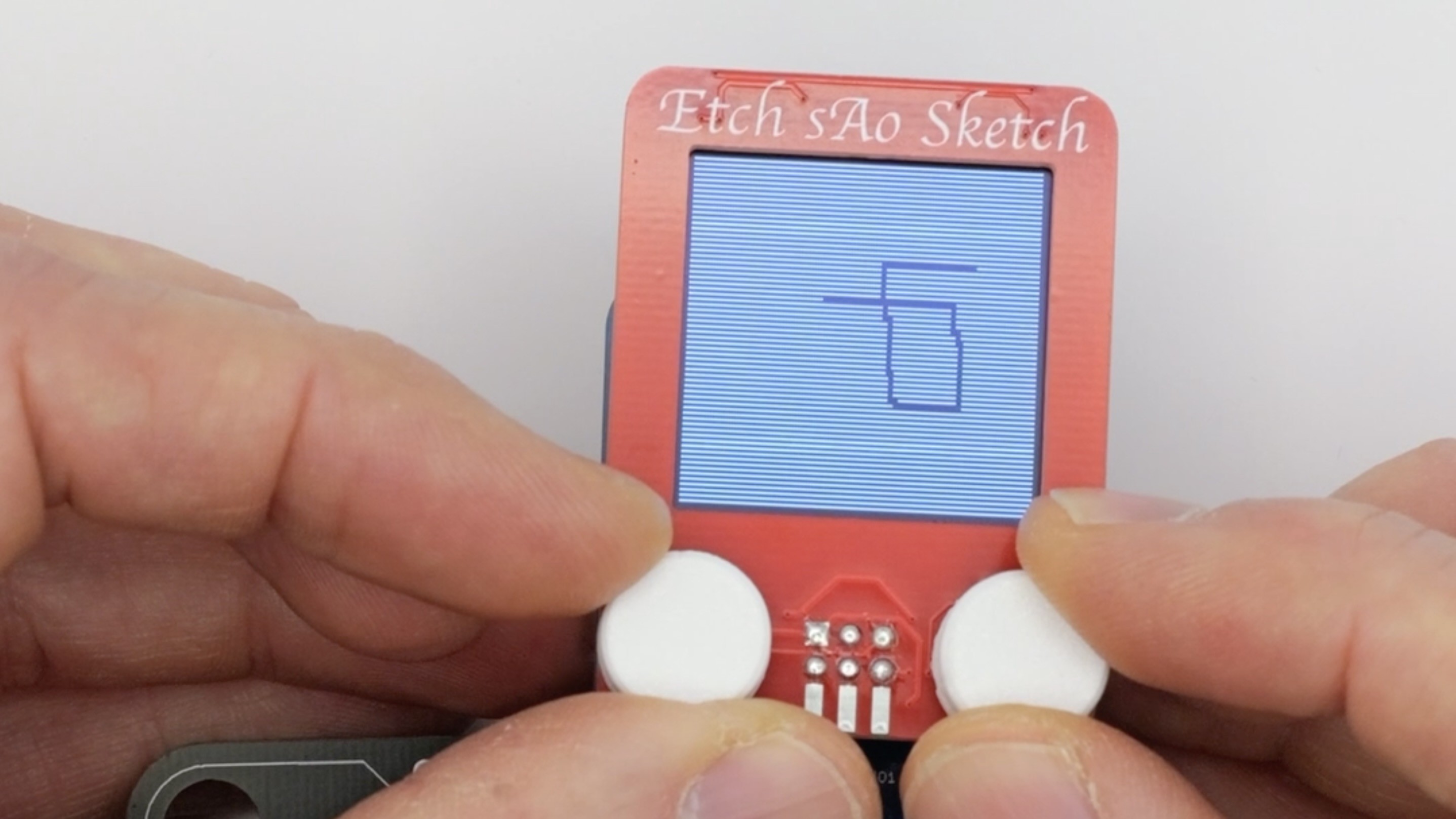
Architecture V1 is the easiest and most direct path to a solution. But it lacks the ePaper, which I think is the magical element that will really make the Etch sAo Sketch pop. OLEDs are nice, but I think people will enjoy ePaper more. This will be my starting point. Maybe using a fully illuminated OLED display, with the drawing point being OFF pixels will sell the look?
ARCHITECTURE V2 (ePaper, I2C-to-SPI bridging, standalone MCU operation, with even more benefits):
- Display is ePaper, which is only available with a SPI interface. Minimal [enough] SPI functionality could be bit-banged through the 4 available SAO lines, but this deviates from the I2C bus standard expected with SAOs. Therefore, I2C to SPI translation is needed. A dedicated solution exists as an NXP SC18IS606 I2C to SPI Bridge, about $3 in low volumes. But a DIY MCU bridge could easily cost less. See MCU point further down...
- The two knobs are still analog pots, optionally connected to SAO GPIO1&2, or tied to the MCU onboard the SAO, enabling stand-alone operation.
- Accelerometer is still connected to SAO I2C lines, and optionally accessible by the onboard MCU.
- The MCU. I could roll my own dedicated bridge on a low cost MCU like this, but I'd like to pick up a lot more functionality by using a small pre-made MCU board. Considering capability, compatibility, support, ubiquity, price, a desire for USB-C to Arduino simplicity... leads me to the RP2040-Zero and ESP32-C3. Both of those are available for < $2. I really like the drag-n-drop simplicity for firmware on the RP2040 (no IDE needed), but I also like that the ESP32-C3 opens the door for this SAO to access Wifi and BT. Perhaps I can configure the footprint on the back of the SAO to work with either board. Otherwise, it's likely the RP2040 simplicity is going to end up in this architecture.
- I2C to SPI Bridge: I can do the direct ePaper/SPI heavy-lifting in the ESP, and offer a simplified (and customizable) protocol to the SAO port in either I2C or UART (UART per the SAO standard). And maybe this DIY I2C-SPI bridge could be a spin-off project library to benefit the SAO community and beyond.
- Having a configurable I2C to SPI Bridge in an MCU also opens the door to other SPI displays, like multi-color OLED and TFT options. This I2C constraint really only exists in the SAO port right now, so not sure that's a big seller. Although, Badge Life and SAOs would benefit more. Considering the whole impetus of this project and the Supercon Add On contest is to stretch into more I2C functionality, why not open the door to SPI too?!
- Does this mean the SAO becomes the badge?
Architecture V2 is going to be my extra credit project.
Can I complete both by October 15?
-
Requirements
09/18/2024 at 13:39 • 0 commentsMust have:
- Display
- Two knobs
- Accelerometer
- SAO connector and I2C control
- A single 2-layer PCBA with maximum size W 40mm x H 50mm
- Completed by Supercon 8 SAO contest deadline Oct 15.
Nice to have:
- A button (could be used to clear the screen without accelerometer, maybe change modes)
- Optional standalone mode, operating from only 3V3 SAO power, including an MCU.
- Accessible, supported, and easy to use MCU with a USB cable and Arduino IDE
- Display using ePaper, although OLED is directly I2C compatible.