Michael Gardi
-
One Last Power Move
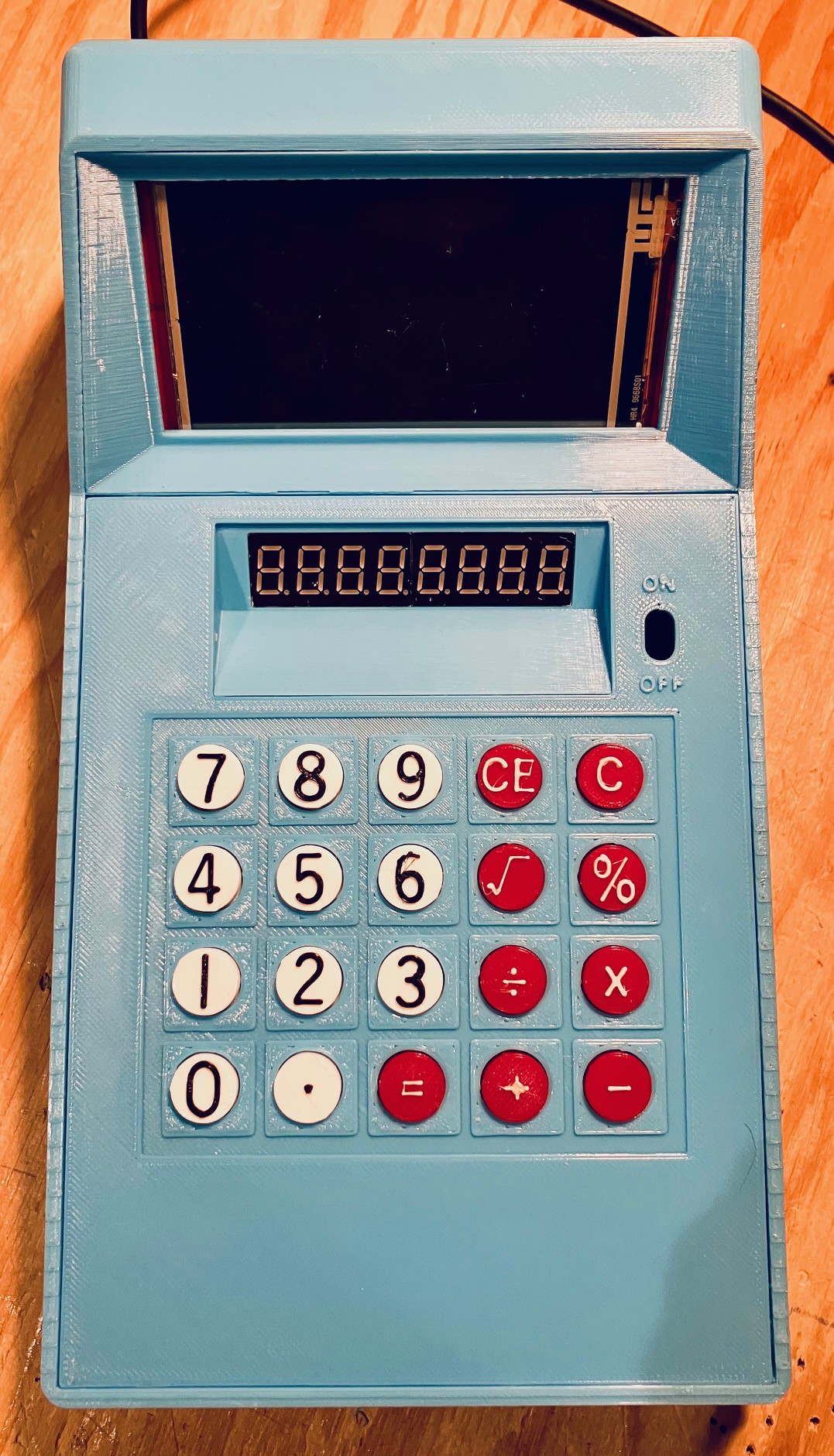
03/20/2025 at 15:28 • 0 commentsNow that the hardware and software is done I added a proper power plug and connected it to the ON/OFF switch.
![]()
-
It's Alive
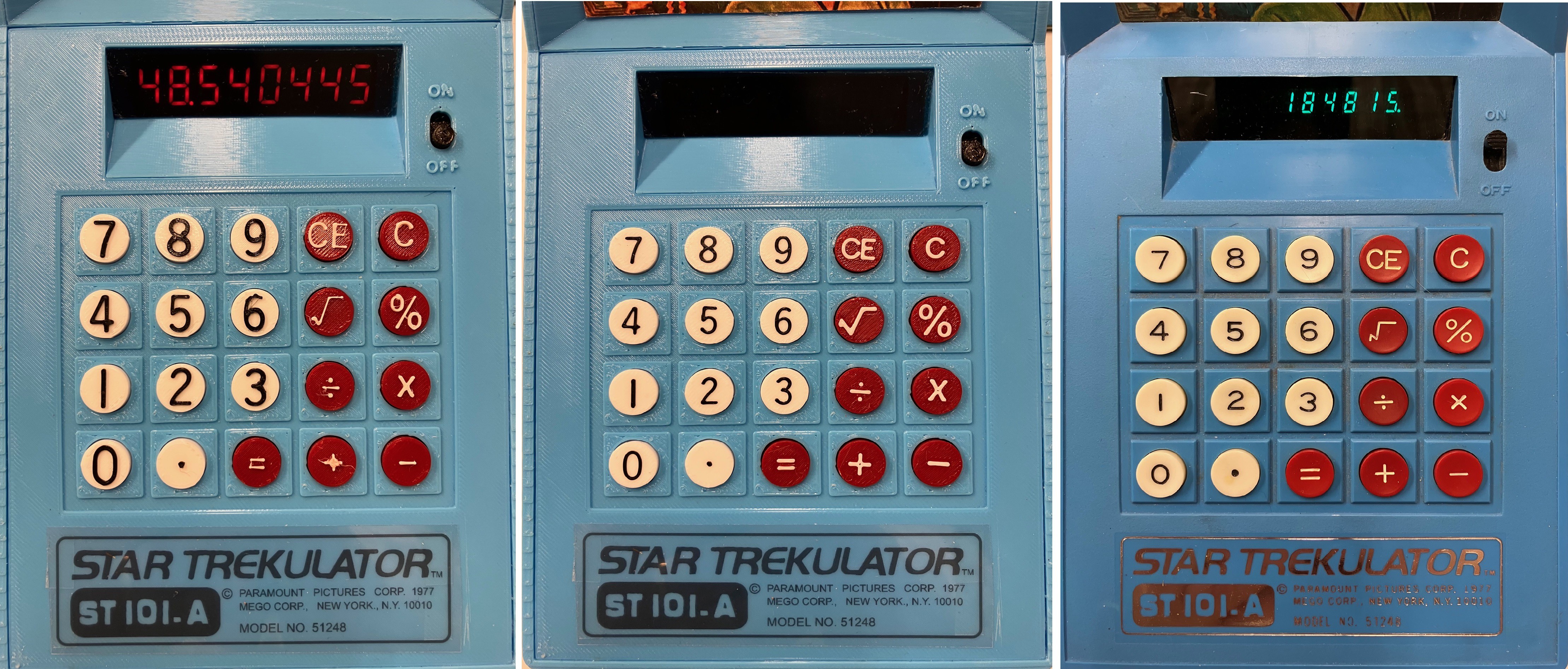
02/15/2025 at 16:10 • 0 commentsThe calculator code has been added to my Trekulator reproduction. It seems to behave pretty well compared to the original. Here is a quick video:
So this is pretty much the end of phase 1, reproducing the original Trekulator functionality. Its now time to have some fun and extend the platform with more Star Trekie goodness. -
New Keys
02/12/2025 at 21:20 • 0 commentsI wasn't completely happy with the keypad keys that I had modeled and printed. Since my printer is only single color I had to extrude the key symbols up from the tops of the key caps and pause the print to switch filaments to change the color of the labels.
My local makerspace (Kwartzlab) now has three Bambu Lab P1S printers with AMS units, and I have been wanting to try out multi-color printing. So I tweaked the key cap models a bit so that the labels were separate "bodies" (objects) inserted into the keys. This allows you to assign different colors to the key and the label in Bambu Studio. At the same time I adjusted the label sketches so that the strokes were at least .8 mm wide. This ensured that they were "drawn" with at least two "lines" of filament.
The result was very satisfying.
![]()
On the left my original key caps printed on my Prusa MK3S+. In the middle caps with my new and improved labels. Of necessity, labels are still a bit larger than the original Trekulators so they can be printed with a .4 mm nozzle, but they are much better defined now and they don't have a rough feel since the labels are flush with the key tops now.
Definitely worth the effort.
-
Yikes!
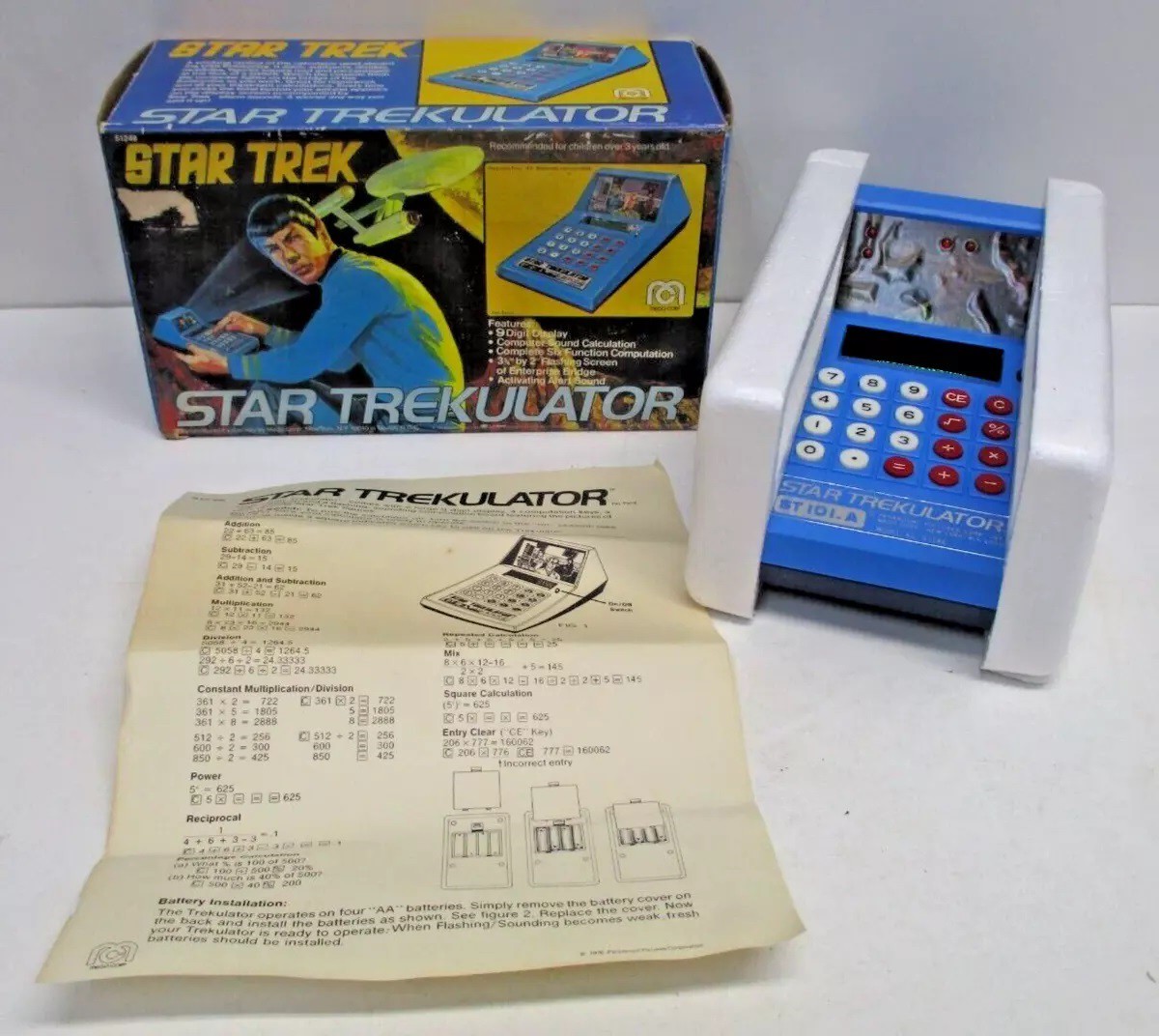
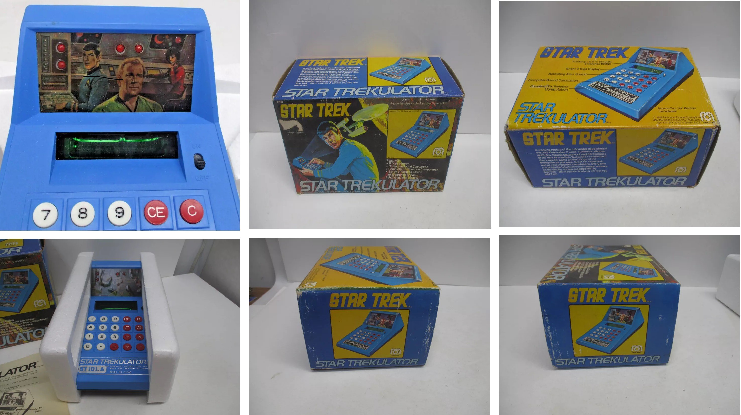
02/10/2025 at 22:48 • 0 commentsThis just popped up on my eBay feed.
![]()
Here is the link: RARE! 1976 Mego STAR TREK - STAR TREKULATOR (Calculator) LIGHTS & SOUND CM2739.
![]()
It's in terrific condition, but the starting bid of US $599.99 is a non-starter for me.
-
Some Finishing Touches
02/03/2025 at 20:59 • 0 commentsI added an ON/OFF switch. It's not wired yet but ready to go.
I recreated the Trekulator decal. I was going to have it printed white on transparency only to learn that my local copy place does not stock white toner for their printers, who knew. So I had to settle for grey which looks fine.
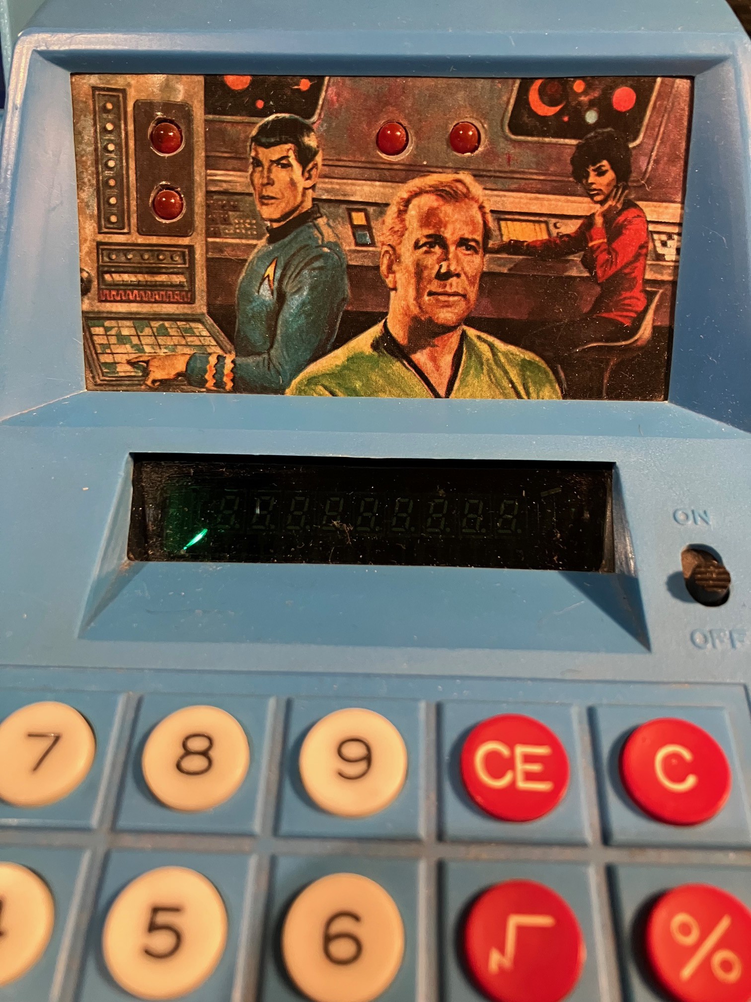
For version 1, I reproduced the still image of Kirk, Spock, and Uhura and just mounted it over the TFT display. I had punched out the holes where the LEDs would have gone. My intention for version 1 was to light up the screen behind these holes red to simulate the LEDs, but while integration testing I noticed the following.
I was running "The Game of Life" to test TFT display. You can see the "active" cells blinking behind the LED holes. Reminds me of static. I think it looks pretty cool so I will likely try to show tiny little "displays" where the LEDs would have been.
Finally I added a translucent blue gel over the 7_Segment display to tone down the bright red a bit and mask the display structure so that you only see the segments when they are lit.
I think I've been procrastinating a bit on the software side. No excuses now.
-
Packaging
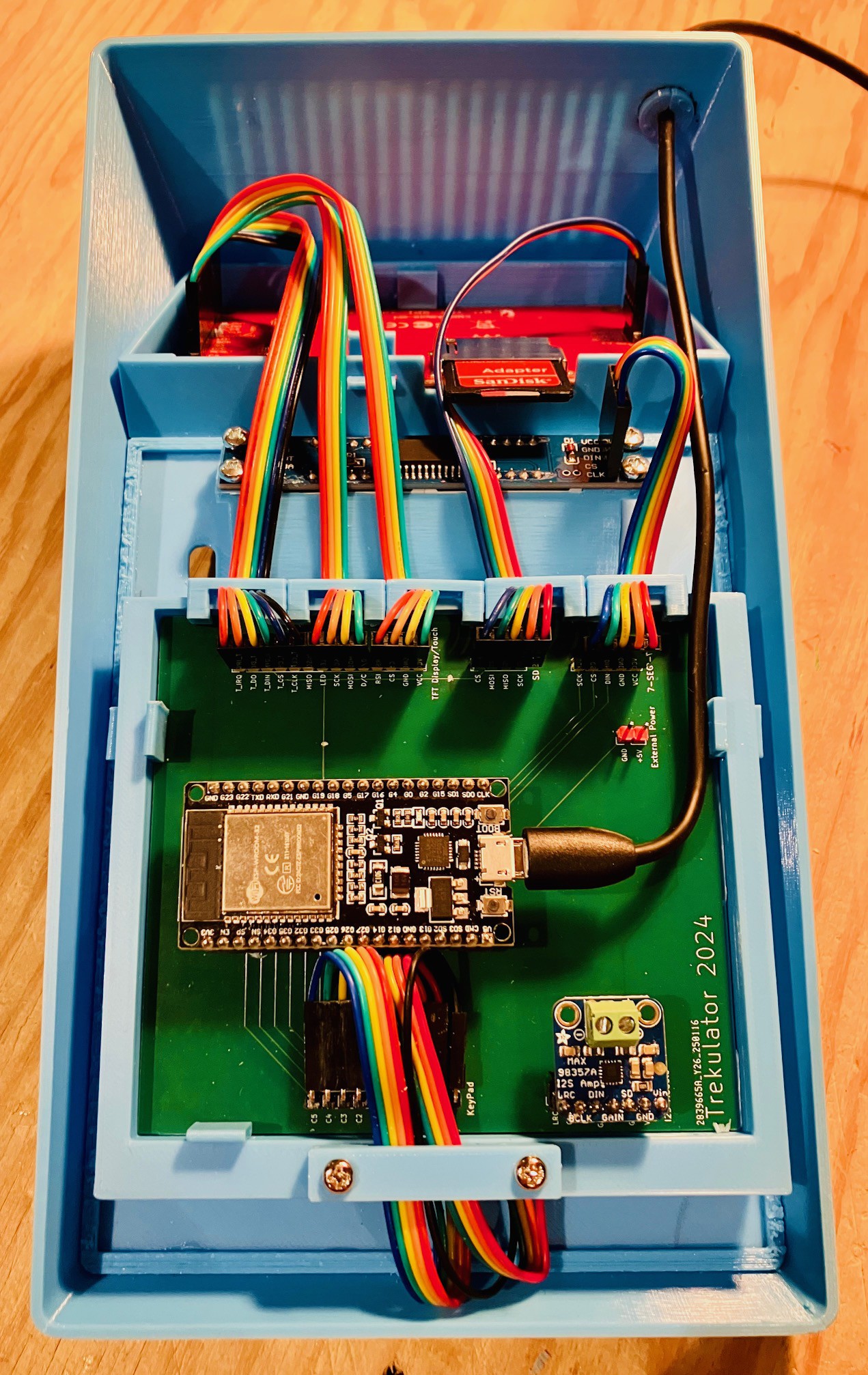
01/27/2025 at 17:01 • 0 commentsThe "wiring" PCBs arrived, so I added the required headers to attach the ESP-32 to the rest of the components.
![]()
I soldered in sockets for the ESP-32 and I2S board.
Thankfully assembly went well. SparkFun Electronics has some nice "Jumper Cables" in short lengths (4", 6", and 12") with many pin number options. They worked out great in this case. I designed and printed some clips to hold the wires flat as there is not that much clearance to the bottom of the case.
![]()
The PCBs and TFT are held in place by L shaped tabs, and the 7-Segment display is screwed on so that it would be easy to print an new case and swap the electronics into it.
I still have to add an external power connector and front panel switch (I'm temporarily running in a USB cable to power the Trekulator and so I can program the ESP-32), but the hardware is basically done.
![]()
Time to write a calculator program.
-
Wire Wrangling
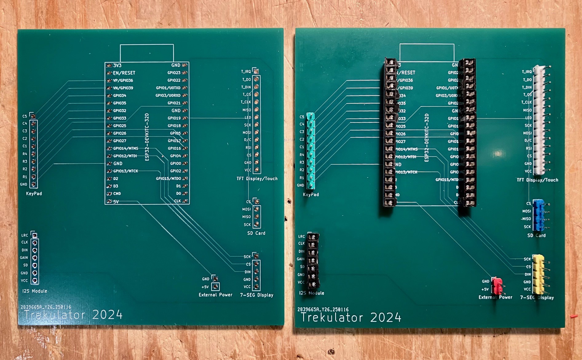
01/14/2025 at 20:32 • 0 commentsWith all of the Trekulator components wired and tested I turned to packaging everything into the case. I had already decided that I would create a PCB to bring some order to the wiring chaos.
![]()
I think there are a couple of I/O pins still available on the ESP32 but not many. So I got to work on the PCB.
![]()
After struggling a bit to get the last couple of traces attached without having to create a via, I broke down and decided to just do a 4-layer board. For the cost difference in fabrication, for what is essentially a one-off, I decided it was worth it.
As I mentioned in a previous log, this PCB is the same size as the KeyPad PCB and will be installed directly above the KeyPad.
-
Mounting the TFT Display
01/14/2025 at 19:51 • 0 commentsI modified the Trekulator large display model to include an indentation to mount the TFT Display. As with the keyboard/CPU panels, tabs are used to secure the display in place.
![]()
With this change the inside of the case is 95% done. I still have to work in an external power connector and ON/OFF switch.
![]()
-
Adding a TFT Display
01/14/2025 at 17:33 • 0 commentsThe original Trekulator has four red LEDs imbedded into the still picture of Kirk, Spock, and Uhura.
![]()
I was about to start adding these when I had a thought. My intention all along was to mount a real display back there for my Next Generation implementation. It occurred to me that with a display I could easily emulate the LEDs for an "authentic" original experience so I decided to avoid some rework and jump directly to adding a display.
I had purchased a 3.5 Inch TFT Display for this purpose. It has 480 x 320 resolution, a touch screen, and an integrated SD card reader; all of which use an SPI interface keeping the I/O pin count down. The display is based on the ILI8488 driver chip which is well supported library wise. These modules are readily available and relatively cheap.
![]()
The screen itself is not wide enough to fill the whole Trekulator display area, but the height is pretty close so I think I can make this work.
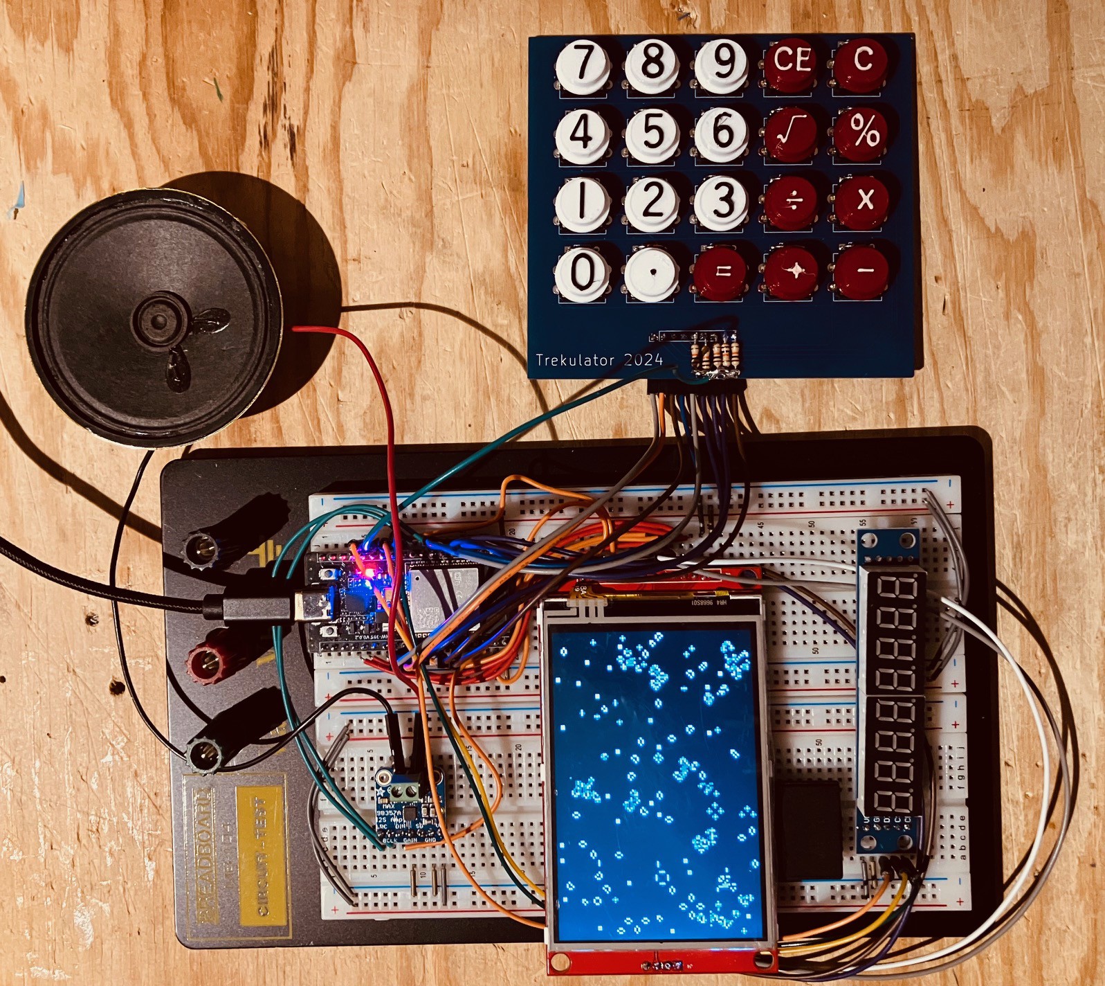
I added the display/touch/SD card to my breadboard and wired it to the ESP32. I removed the Adafruit MicroSD Card Breakout Board since I no longer needed it. I am using the TFT_eSPI library to communicate with the display devices. The library come with many great examples to test the device. Below is a "Cellular Automata" test of the display.
I also tested the SD Card and touch capabilities. With the display working, all of the components for my Trekulator reproduction are in place. Now I just have to figure out how to cram all of this into the case, and oh ya write calculator program.
-
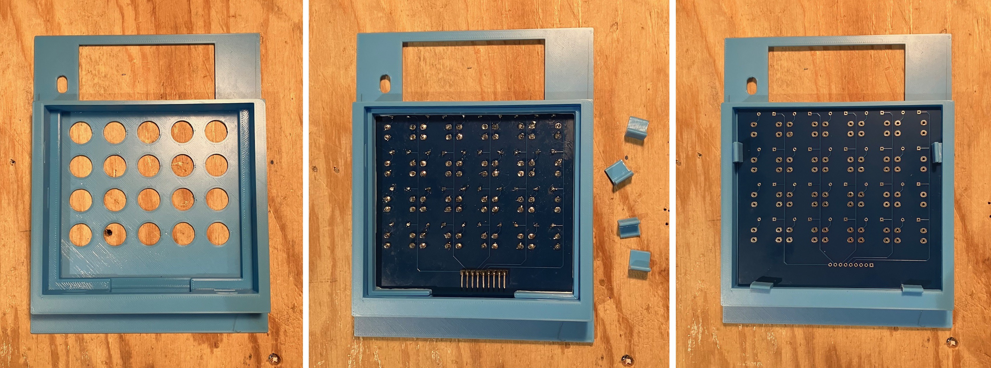
Mounting the Keypad
12/12/2024 at 16:36 • 0 commentsI designed a mounting block for the Trekulator keypad.
![]()
I attached this with CA glue to the back of the front panel. To ensure the alignment of the keys with the holes I glued the mounting block to the back with the fully populated PCB in place.
![]()
With the keypad PCB in place I added the spacer ring (right side of the first image above). I created the block with a depth that can accommodate two PCBs. I did this having decided that I will create a second PCB to hold the ESP32, I2S, microSD reader, and amplifier cards. This second PCB will be the same size as the keypad and will greatly simplify the overall Trekulator wiring. In the rightmost picture immediately above I have used a keypad PCB as a placeholder for this new board, and used some 3D printed clips to hold everything in place.
Trekulator - Where No Maker Has Gone Before
Phase One: Make a reproduction of the Mego Corporation Star Trekulator Calculator. Phase Two: Reimagine the device with a modern aesthetic.