 Michael Gardi
Inspiration
Lately Hackaday has been my muse!
My MCM/70 Reproduction was inspired by Kristina Panos February 23, 2022 blog post: INPUTS OF INTEREST: CANADIAN MCM/70 WAS KINDA LIKE THE FIRST CYBERDECK. Here was a beautiful Canadian built personal computer from the mid 70s that I had no idea existed. I had to learn more.
The Commodore CHESSmate Reproduction I did was triggered by the November 14th, 2023 Maya Posch post: THE QUAINT HISTORY OF THE COMMODORE CHESSMATE in combination with having just met Peter R. Jennings, author of MicroChess. Fate? Coincidence? Either way I felt compelled to move forward.
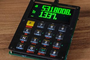
With Al Williams July 19, 2024 post: RETRO CALCULATOR PANDERS TP TREKKIES... OR TREKKERS it was love at first sight. I was hooked by the whole retro future look of the Trekulator, and it didn't hurt the that units were made using my favorite blue color.
First Steps
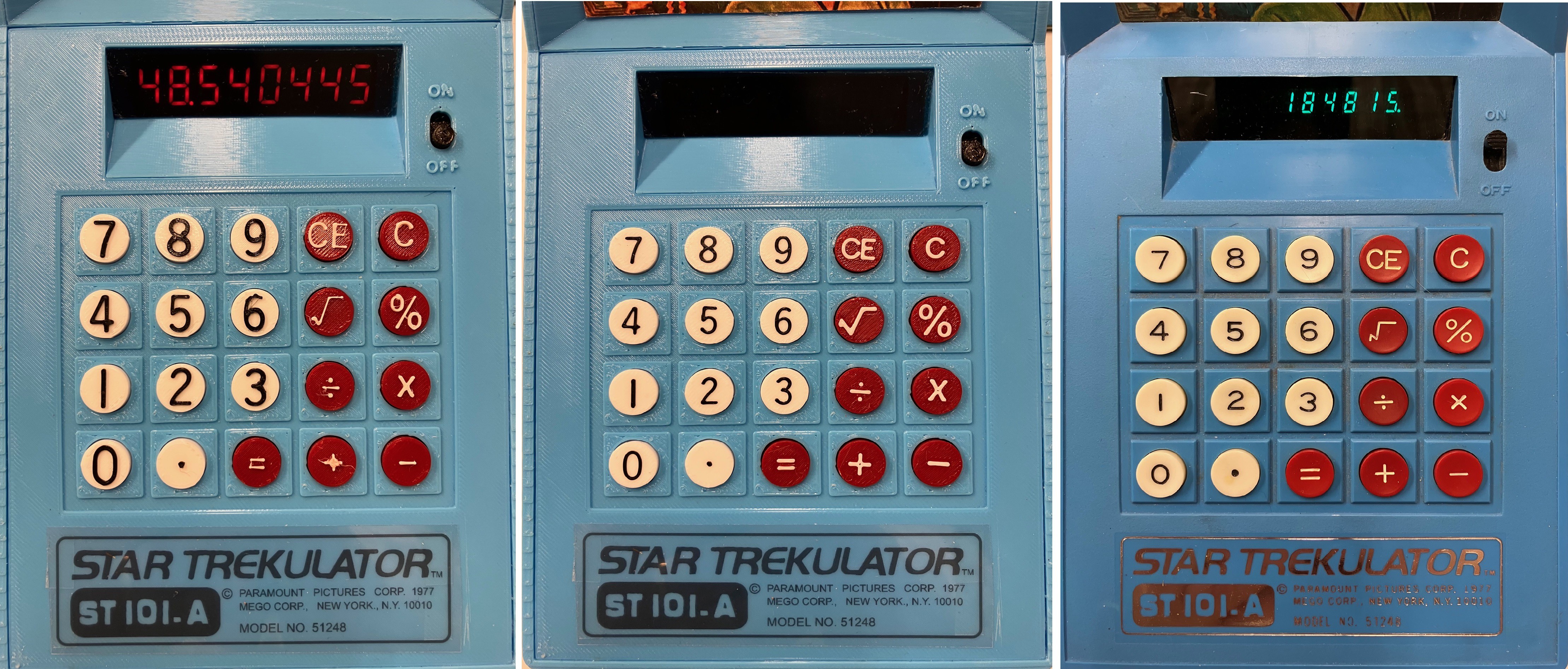
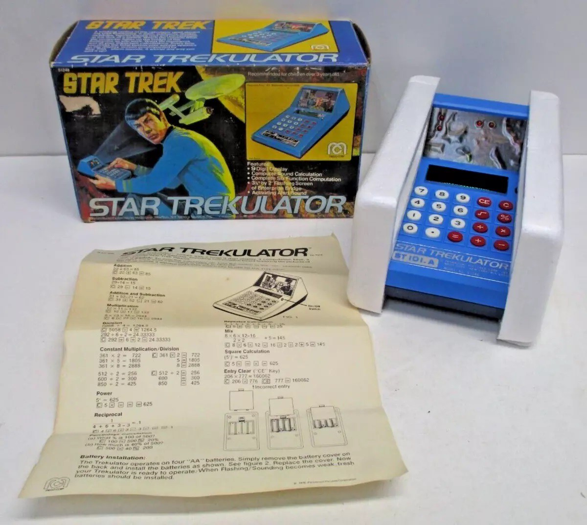
I was lucky enough to find a sort of reasonably priced Trekulator for sale on eBay. It was just the unit itself with no box or instructions plus it doesn't power up (hence the lower cost). As usual, shipping and customs charges (I'm in Canada) added about 66% of the original cost to the total. Sigh. However, given the choice of trying to model something from an original or from photos, I'll pick (and pay for) a real object any day. The Trekulator photo at the top of this project is the one I purchased.
Perhaps a Phase Three project will be to try and get the Trekulator working, but right now I'm keen on 3D modelling the case as my first step.
Another Montage
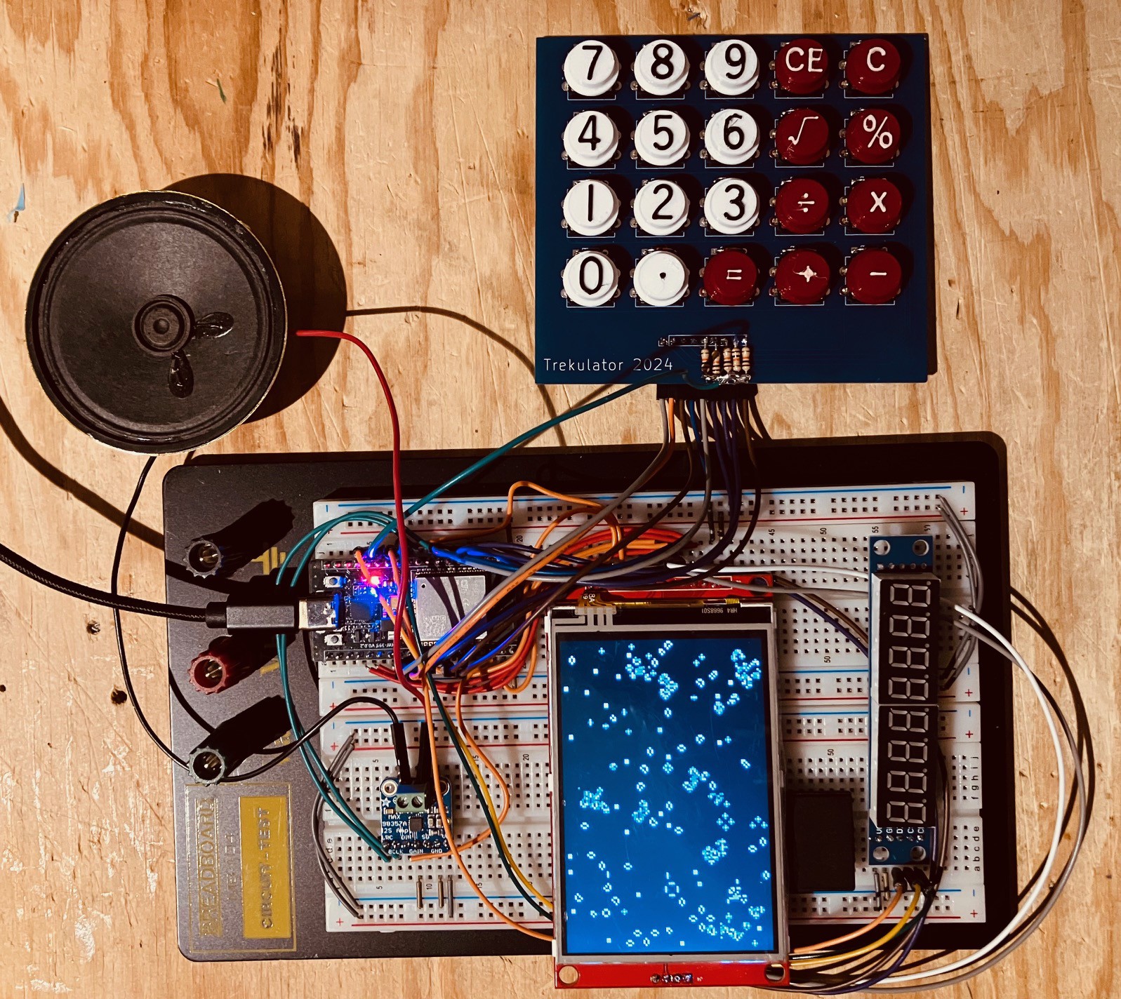
Picture a montage of me printing and soldering and building all at fast-forward speeds. At this point, given the background and design described above, I went ahead and finished my Trekulator reproduction. If you are interested in the details of how this happened I would strongly encourage you to have a look at this project's logs for the complete picture. Here is a handy link: Project Logs.
Wrapping Up For Now
You will see in the logs that I managed to create a pretty faithful reproduction of the original Trekulator. I then went on to create a Next Generation Trekulator. Here is a quick video of it in action.
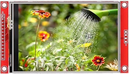
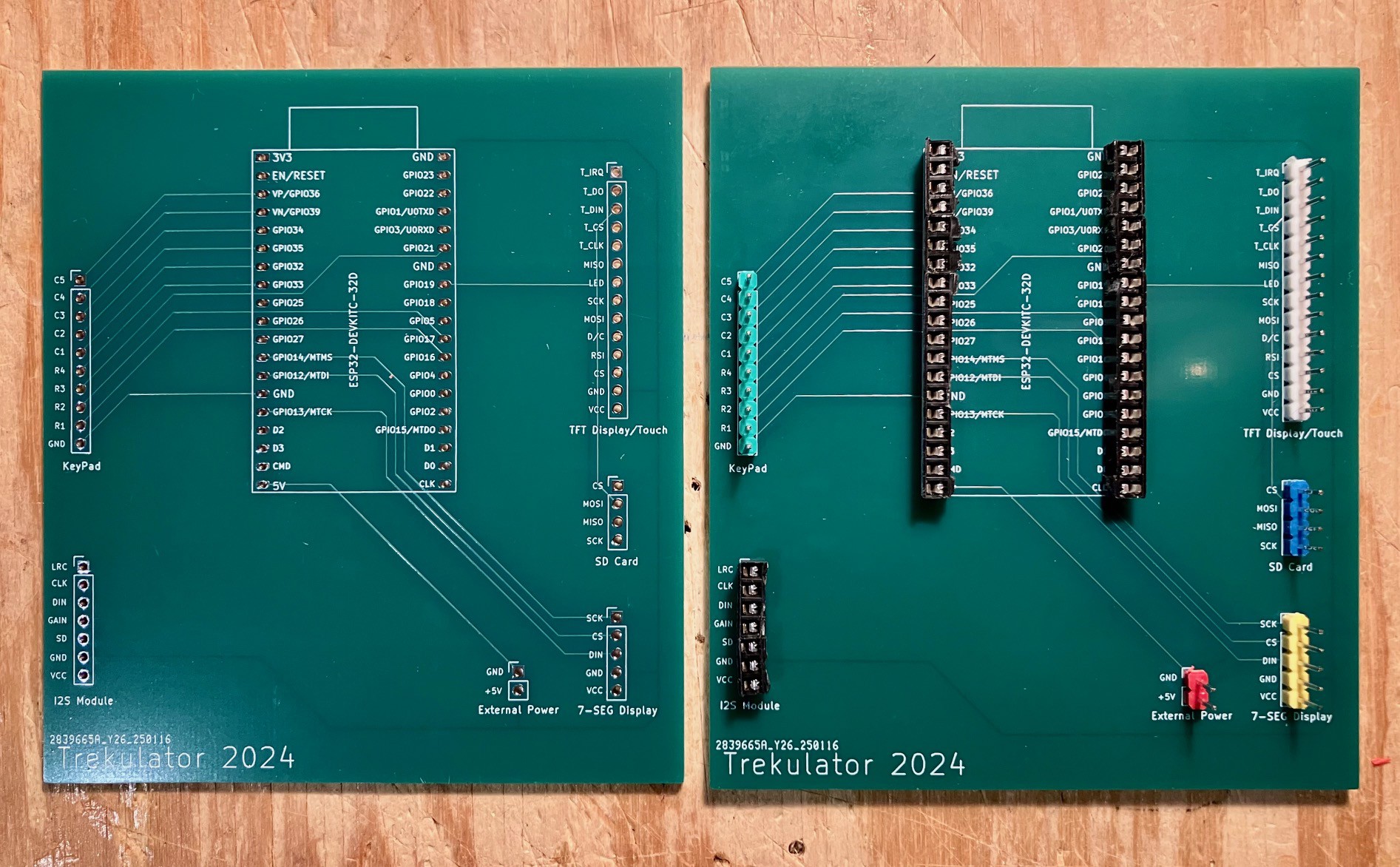
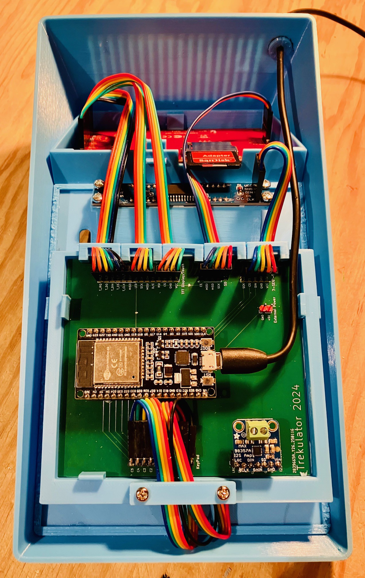
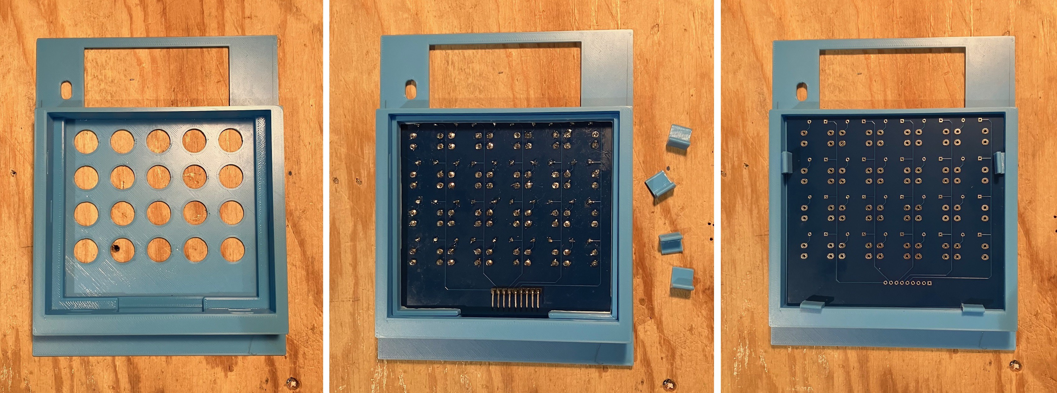
The main focus of the Next Generation version was the screen. I added the TFT touch display that had a built-in SD card reader. As you can see from the picture below, the actual TFT Display is not centered on the PCB.
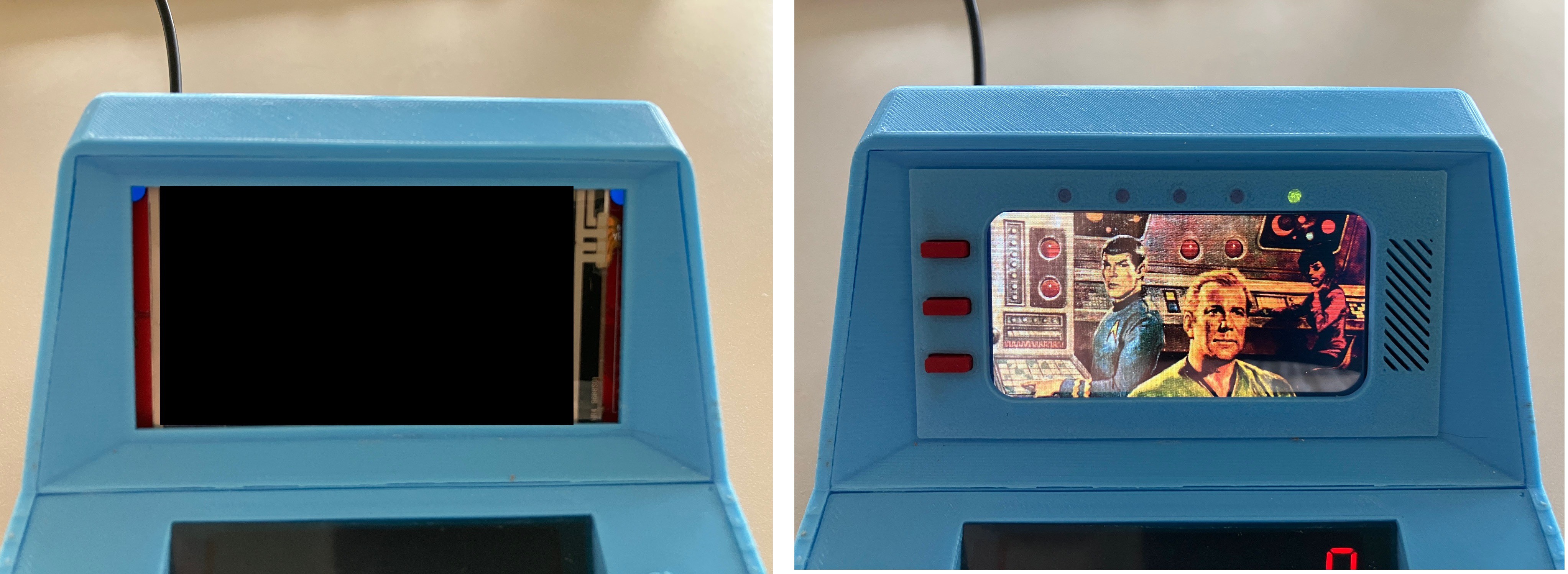
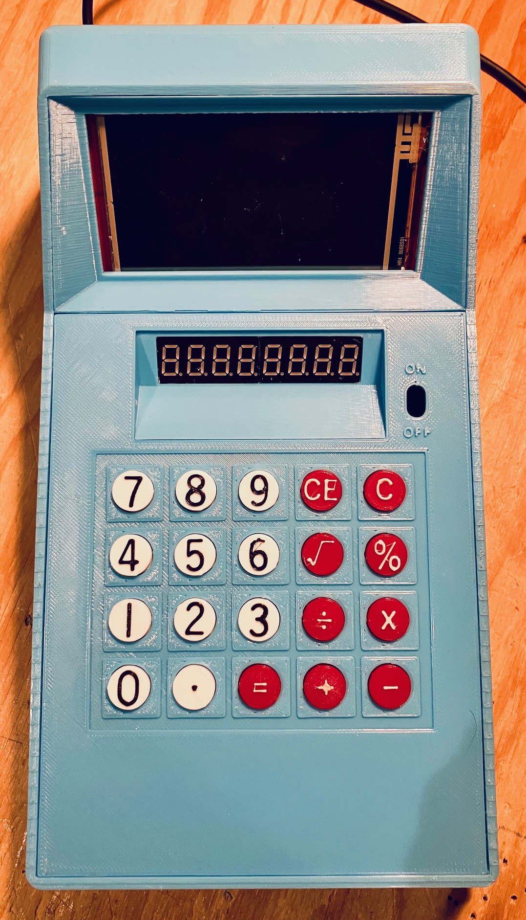
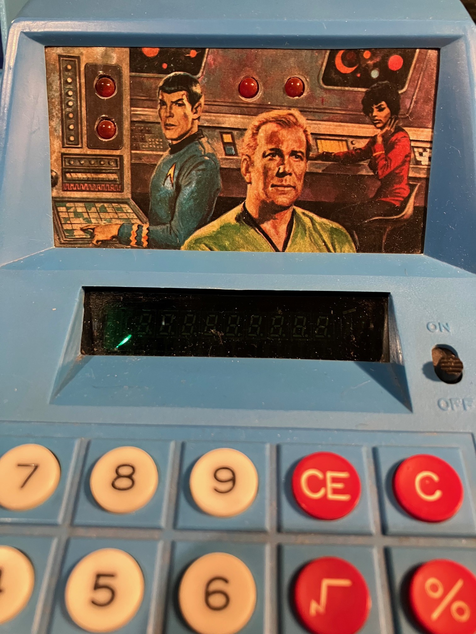
As a result of this and because of space constraints I was not able to center the Display in the Trekulator window. I decided I needed a mask to expose just the central part of the screen. The end result is on the right below. I scaled the image of the original's cardboard backdrop and centered into the open area of the mask.
Lest you think that I sat down and finalized the look and function of the mask one and done style, think again.
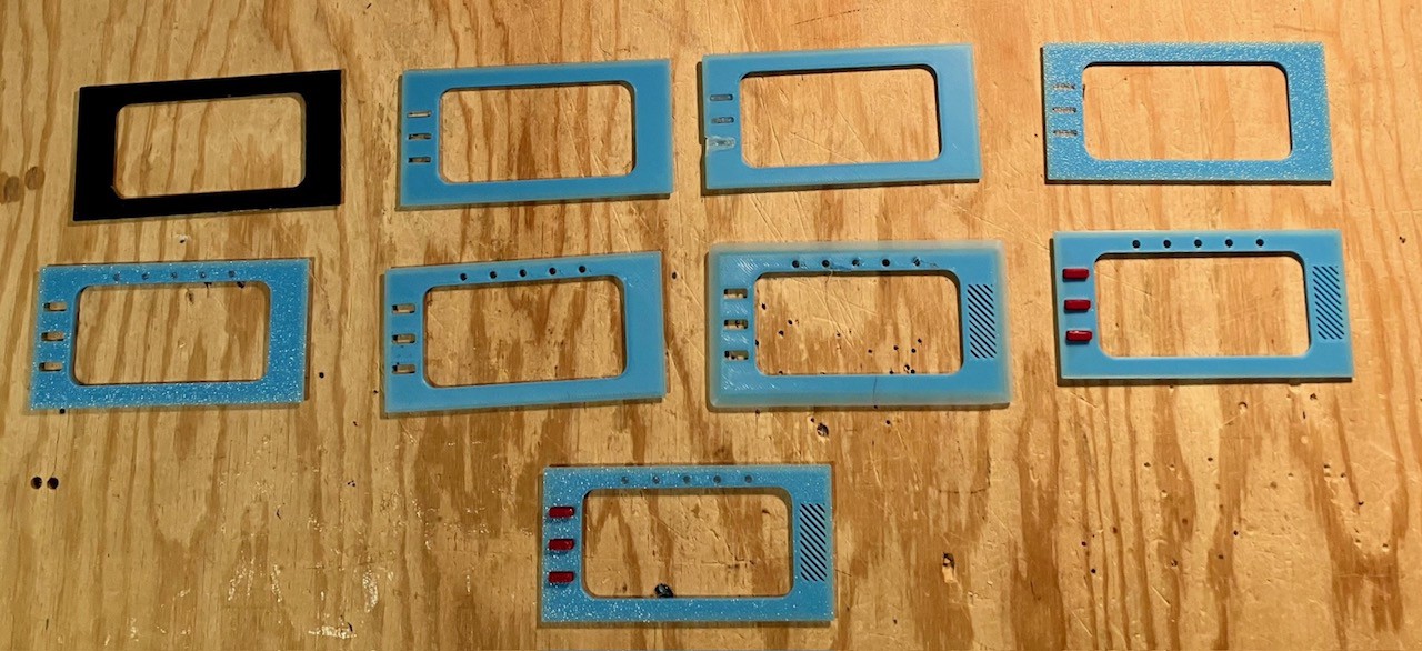
As you can see I finished with a symmetrical look. In doing so I ended up covering part of the actual useable Display, mostly on the left hand side and the top. I started thinking about how I could take advantage of this situation and minimize the waste.
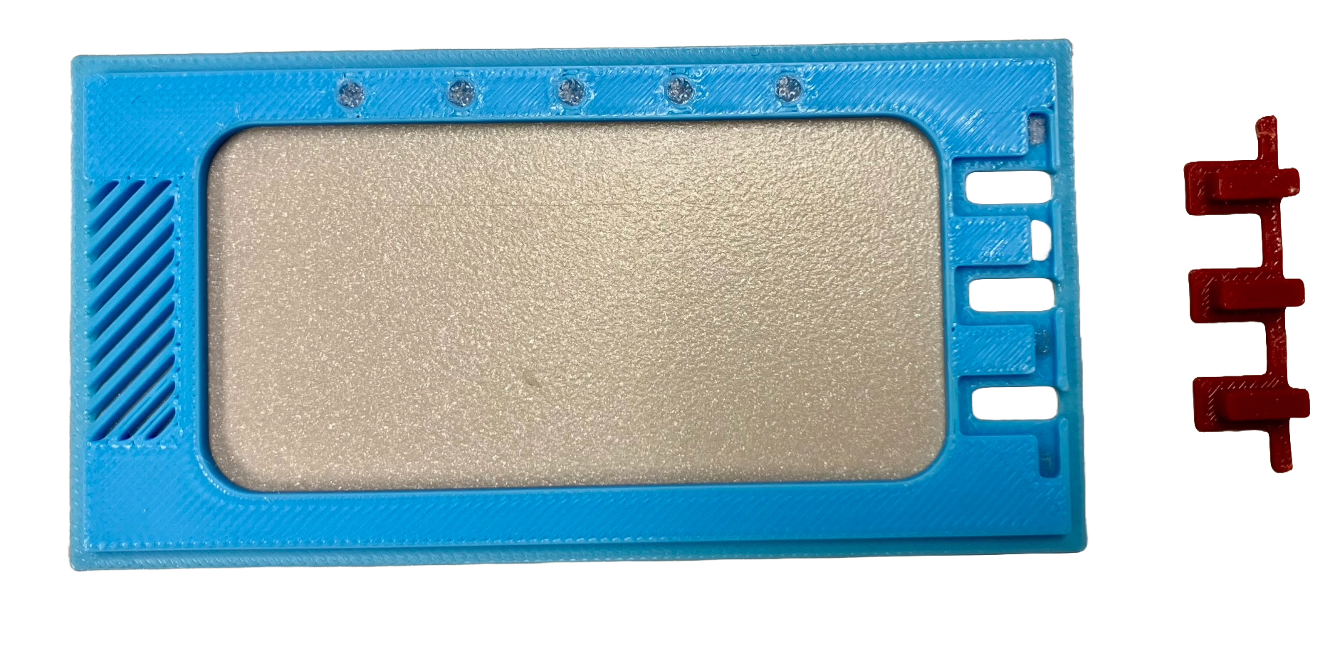
This is the back side of the mask. Along the top I added a row of five holes. I used the Bambu printers at Kwartzlab to print the mask in two colors, blue frame and transparent filament holes. This effectively created a row of five "light pipes". Because the holes are backed by the actual Display I'm able to "draw" colored circles behind the pipes to simulate Blinken lights.
I also created a column of three "buttons" on the left hand side as seen from the front. The red piece seen above fits into the slot with the three buttons pushing through the front and with only the base "strip" glued in. When the mask is in place, pushing the buttons applies pressure to the edge of the resistive touch screen...
Read more »


 svofski
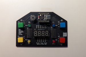
 Julius
 deʃhipu