davedarko
-
I2C hickup
10/25/2024 at 01:37 • 0 commentsOn the TARS SAO there are two quiic connectors, one was meant to connect to the I2C0 and the other to I2C1 capable pins of the RP2040 module. Sadly I mixed up pins and numbers and managed to connect both to I2C1 pins, just different ones. So best to ignore the SAO QUIIC connector. A rough I2C scanner is now running on TARS, making it possible to check for things on the bus. I just hope the badge RPI gets along well enough with a multi-master situation.
-
I2C peripheral and "EEPROM"
10/24/2024 at 05:38 • 0 commentsArduino made it fairly easy to setup the I2C connection as a peripheral. I was able to read data from I2C and set that data as the displayed name of the simple addon owner for the name tag program! I Realised I have used wire1 for badge connection though. For the quiic connector I'm using wire apparently.
-
with great power comes great anxiety
10/11/2024 at 07:49 • 2 commentsSo I essentially have a handheld now, since there's a display, a sort of d-pad and an A and B button. There's a menu that took inspiration from my #Flipper At Home "project". I'm currently trying to come up with some app ideas, maybe I can write a small snake game for it. Since it has I2C, I should also consider having a program to scan both I2C ports. I always wanted a scanner that can also give a "lucky guess" with the address and be prepared to read out some values and already convert them.
Whatelse could this thing benefit from? What should I write?
-
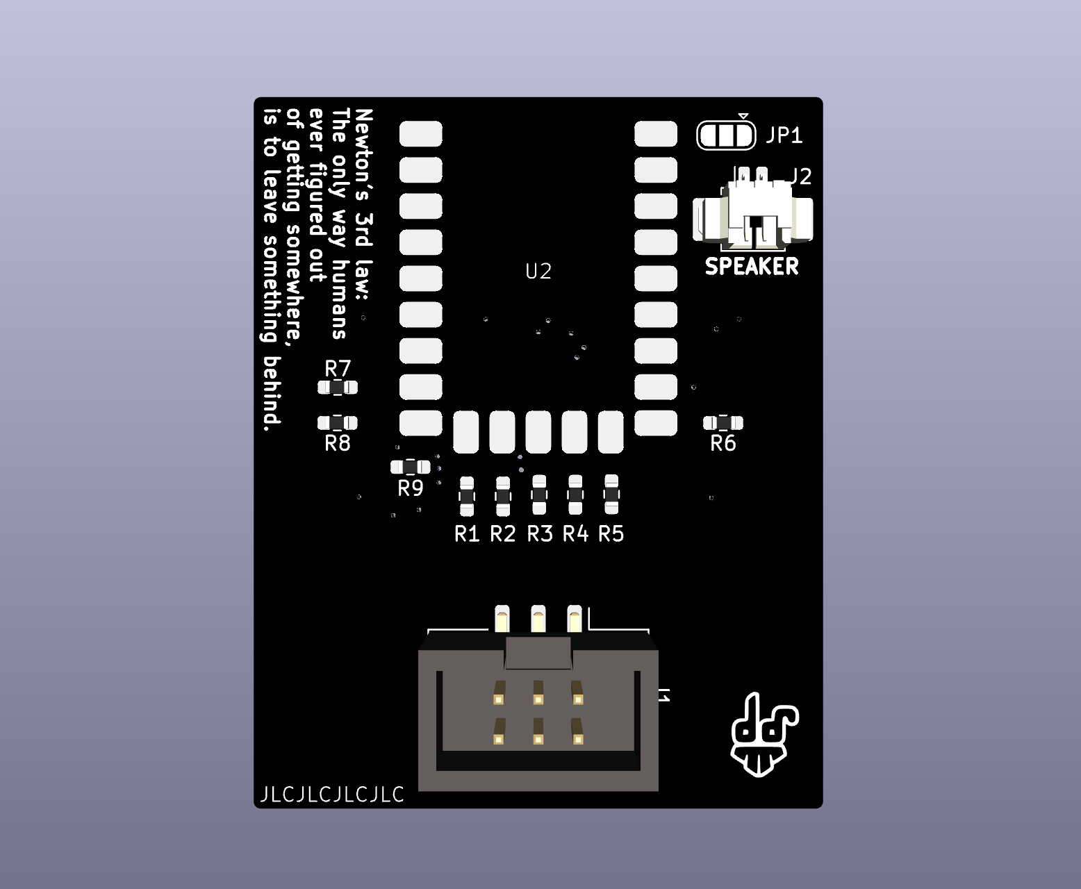
adding audio
09/22/2024 at 22:24 • 0 comments![]()
I remembered to check https://pico.pinout.xyz/ for some hidden treasures in the advanced pin descriptions for PIN0 and PIN1 and I had completely forgotten the PWM functionality!
With the help of this wonderful library https://github.com/khoih-prog/RP2040_PWM, I managed to get a speaker connected to GPIO0 and 1 in a pushpull configuration, meaning channel B is an inverted A. I remembered a CNLohr video where he used a pwm output with inverted channel of an attiny85 to basically amplify a microphone?
-
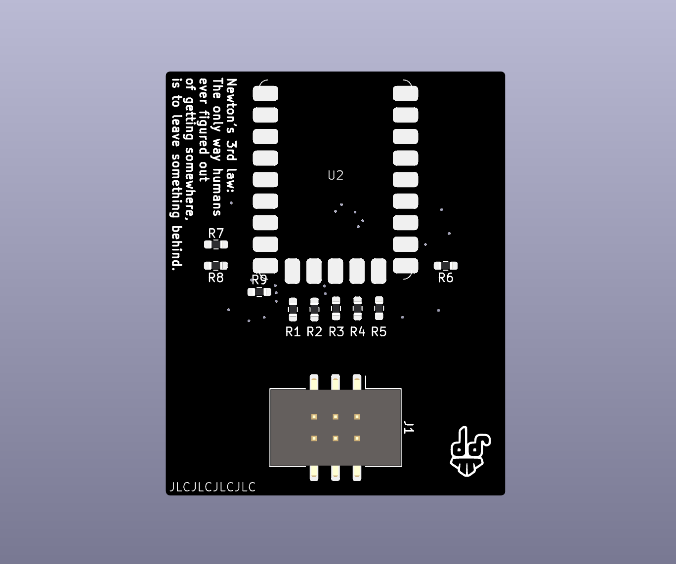
Progress on the PCB
09/22/2024 at 10:29 • 0 comments![]()
I have rerouted some display pins and freed up an RX-TX connection that I could use for a serial infrared communications bridge. Not sure I want to, but it's free now :D There's four more pins that have the ADC pins connected, at least in the pinout for this board it's marked that way. Should I add more features or should I just ship it?
There's also a cue light now, the indicator LED for TARS making a joke, it's a neopixel, but maybe I'll just turn it into a white LED.
-
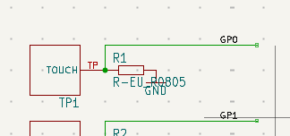
TouchyTouch by todbot
09/18/2024 at 20:55 • 0 commentsThis evening I soldered up a small prototype to test the touchytouch library that todbot wrote and used for the his PicoTouch project. For reference, this is where I started from with the touch buttons, with resistor values of 1M Ohm. I've cut up a blank copper pcb at the hackspace and soldered four of the gazillions resistors we have to the board. I'm very pleased with the result, so there's going to be touch buttons for TARS for menus and stuff.
![]()
-
PCB progress
09/17/2024 at 22:23 • 0 commentsAs you can see in the videos, I'm using a WaveShare RP2040-Tiny module, that comes with a "programming dongle", meaning you can program it via usb-c and use the
bootdoot and reset buttons to your liking. If you're done, you're left with a small PCB that's also SMD mountable - nice!The ST7735S display that I'm using, can be soldered either through a slot on the back of the board, or just under the display. So I created a footprint that mounts on the front, so I will have more room on the back for the RP2040 module and some light panels for highlighting the "TARS" and "TARS" in braille font. I can probably use the onboard neopixel and safe 10ct - bargain!
The display footprint is created, next up is going to be the RP2040-tiny module. In parallel I will test some touch button code with rudamentary hardware.
-
plenty SAO ideas
09/17/2024 at 18:30 • 0 commentsSo this ST7735S display has 160x80 pixels in RGB565 color range and gives you some options. I did find a relatively cheap ESP32-C3 board with additional LCD module for my #Flipper At Home , for that I wrote a little menu but never took it any further.
I will hopefully be able to throw some hommage to other franchises like Hackers, since the display is able to show some stuff and I won't be able to spin up more boards till supercon. There's an obvious flipper zero simple add-on to make, but also a pager SAO that might incorporate its own transceivers to send messages.
TARS SAO
A simple add-on inspired by Interstellars robots with 6 touch buttons, a speaker and a 160x80 pixel display, controlled by an RP2040 board