 Andy Geppert
-
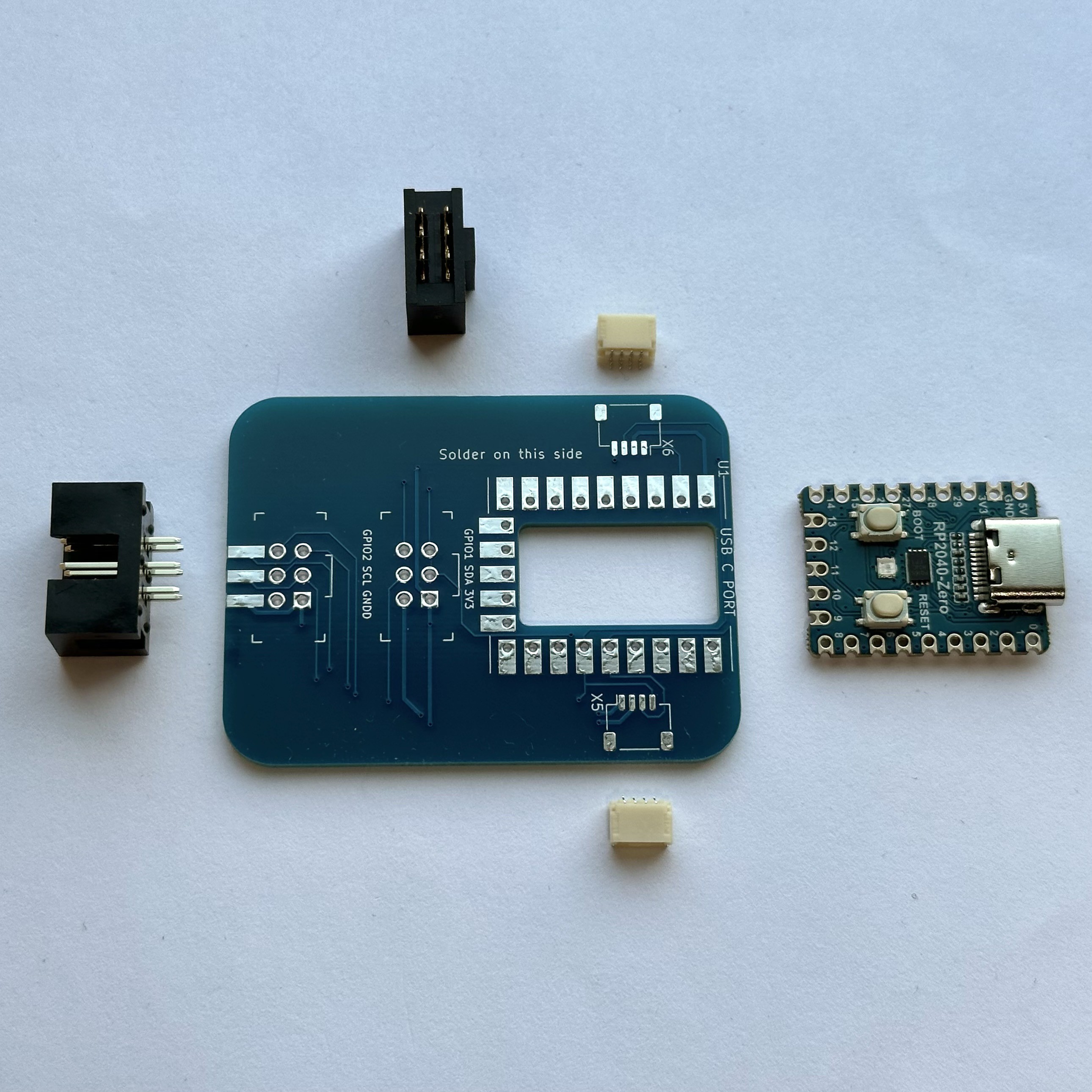
1Gather the components
CAUTION: Do not connect USB-C power to the SAO Demo Board when it is connected to a host Badge. This will inject 5V into your badge's 3.3V SAO Power Bus.
Contents of the kit:
- SAO Demo Controller PCB (right side of this image)
- RP2040-Zero Microcontroller (center)
- SAO Header, shrouded male pins (left side of this image)
- SAO Socket, female socket (top of this image)
- A pair of QWIIC/STEMMA sockets (white)
![]()
-
2Solder on the QWIIC/STEMMA sockets
Tin one of the larger square pads of X5 or X6.
Keep the solder hot and slide the connector into alignment with the other pads.
Remove the solder pencil after the connector is positioned, and don't move the connecter while the solder cools, or afterwards. If you have to reposition the connector, reheat the first solder pad, then carefully adjust the connector position. If you apply force to the connector with only one solder joint, you risk tearing the solder pad off.
Solder the other square pad on the opposite side of the connector.
Then solder the four pins.
Repeat for the second connector.
-
3Solder on the RP2040-Zero
The RP2040-Zero is installed with the USB-C port towards the outer edge of the main PCB, with the buttons facing up, on the backside of the main PCB which says "solder on this side."
Align the RP2040-Zero by borrowing your friends' spare 0.100" header pins.
Solder the castellated edges of the RP2040-Zero to the base PCB.
-
4Solder on the SAO Shrouded Header Pins (connects to your badge)
Choose either the left board edge, or the backside of the main PCB.
The notch is to be oriented toward the backside of the board, or toward the notch on the silk screen.
If you want to leave your options open, solder the included header to the edge of the board, and find another one later on to solder to the backside of the board. Then you can use either one.
-
5Solder on the SAO Female Socket (connects to your downstream SAO that you want to control)
Insert the SAO Female Socket from the front side of the board, with the notch up.
Complete the 6 solder connections on the bottom side of the board.
SAO DEMO Controller
A small inline SAO with an RP2040 used to demo SAOs that require smarts, but do not have it built-in.
Discussions
Become a Hackaday.io Member
Create an account to leave a comment. Already have an account? Log In.