Andy Geppert
-
SAO Demo Controller V2 Design Improvements
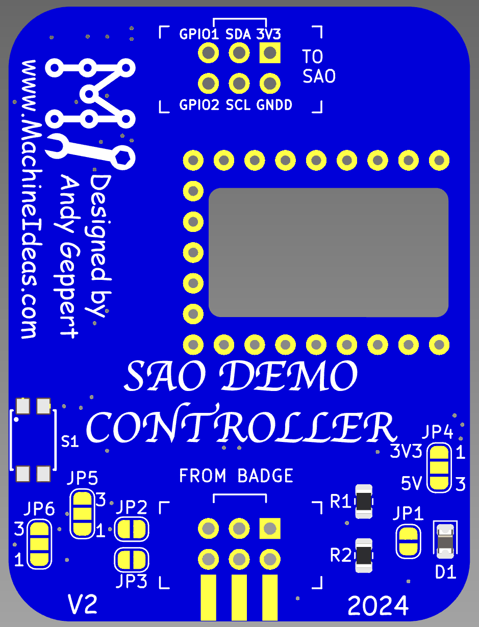
10/22/2024 at 13:41 • 0 commentsAfter some hands on experience with V1, I've decided to enhance the design and squeeze in another round of boards before Supercon. These are all feature additions which preserve V1 functionality. Front side:
![]()
The changes are:
- SAO output moves to the top edge to make it easy to access the back of our SAO while still plugged into the demo controller. This helps with bring-up of your SAO.
- The RP2040-Zero moves to the front face of the board for easy access to it's buttons and RGB LED.
- Power management is improved with a diode to block current flowing from the USB C port of the RP2040-Zero back into the badge.
- Default voltage to downstream SAO is now 3.3V provided by the RP2040-Zero. A solder jumper is available to change downstream SAO power source to be VIN/5VUSB, if needed.
- Downstream SAO (and QWIIC) port GPIO1 is selectable as GP1 or 26, GPIO2 as GP0 or 27 to improve compatibility with different SAOs that my brother and I are working on.
- Downstream SAO GPIO1 and 2 can be pass-through from the badge SAO port with solder jumpers.
- Added a button to control RP2040-Zero (mode selection, if desired).
- Added a voltage divider to measure incoming power with RP20240-Zero.
- Renumbered RP2040-Zero symbol/footprint to match Waveshare documentation.
Backside:
![]()
Now I need to add a switch, 2 resistors, and a diode to the kits!
-
DHL is here!
10/03/2024 at 03:26 • 0 commentsI sure do like seeing that yellow truck show up these days!
Out with the old, in with the new:
![]()
Will it work?
![]()
YES! Now I can get on with development and troubleshooting the new Core4 that just showed up as well. This capability is going to be very convenient for the other SAOs I'm working on!
![]()
I'm really glad I added the QWIIC/STEMMA ports. Those ecosystems have a lot to offer, including pre-made wiring and wire-to-breadboard options. Check 'em out:
https://www.sparkfun.com/qwiic
https://learn.adafruit.com/introducing-adafruit-stemma-qt/what-is-stemma
There are many screens and sensors to experiment with.
-
KiCAD Copy and Paste
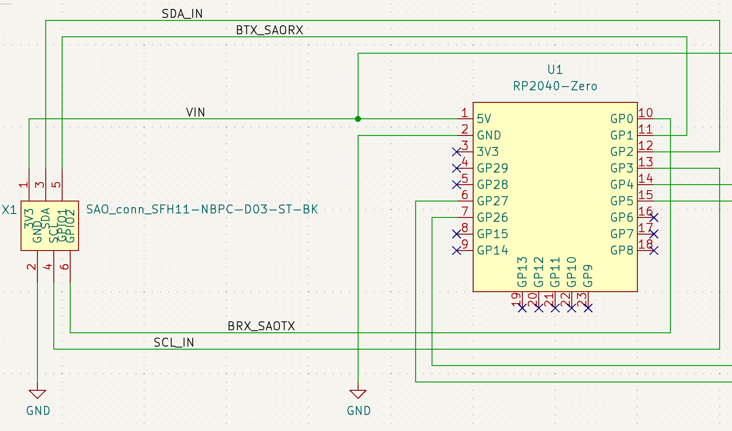
10/03/2024 at 03:13 • 0 commentsStarting with an existing SAO project makes this project pretty quick to spin up. From a schematic perspective, it looks like everything is passive, with just five footprints to place.
All I need from the badge which is the power host, are two of the size SAO pins. But I hate to leave pins unconnected, and I have use case brewing that will help me prototype another SAO, so here is how I plan to use all size pins of the host side SAO connection:
![]()
I'll route the I2C into a spare I2C port of the RP2040 so I the RP2040 can be configured as a slave on the badge I2C Bus. By doing this, the RP2040 can become an advanced I2C device, and control several other things down stream. Such as: a SPI device, analog in/out, another I2C bus, or expanded GPIO. I'm considering this for my Etch sAo Sketch that would use an ePaper display, which only come in the SPI variety as far as I know. Having this capability in the SAO Demo Controller will let me experiment with the concept.
And if that proves to be too difficult (it's certainly not trivial if I want true bidirectional I2C behavior), by Plan B for that project is to use the GPIO of the SAO port as a UART, with the RP2040 translating simple UART commands into SPI control for the ePaper.
Both of these pin pair usages are not core to the SAO Demo Controller, but I feel better connecting those pins to the RP2040, and letting them be ready for possibilities yet to come.
The downstream side will be configured like this:
![]()
This allows your to configure the RP2040 to drive the default I2C bus and communicate with your downstream SAO, and optionally, two QWIIC/STEMMA ports for testing break-out boards and accessories.
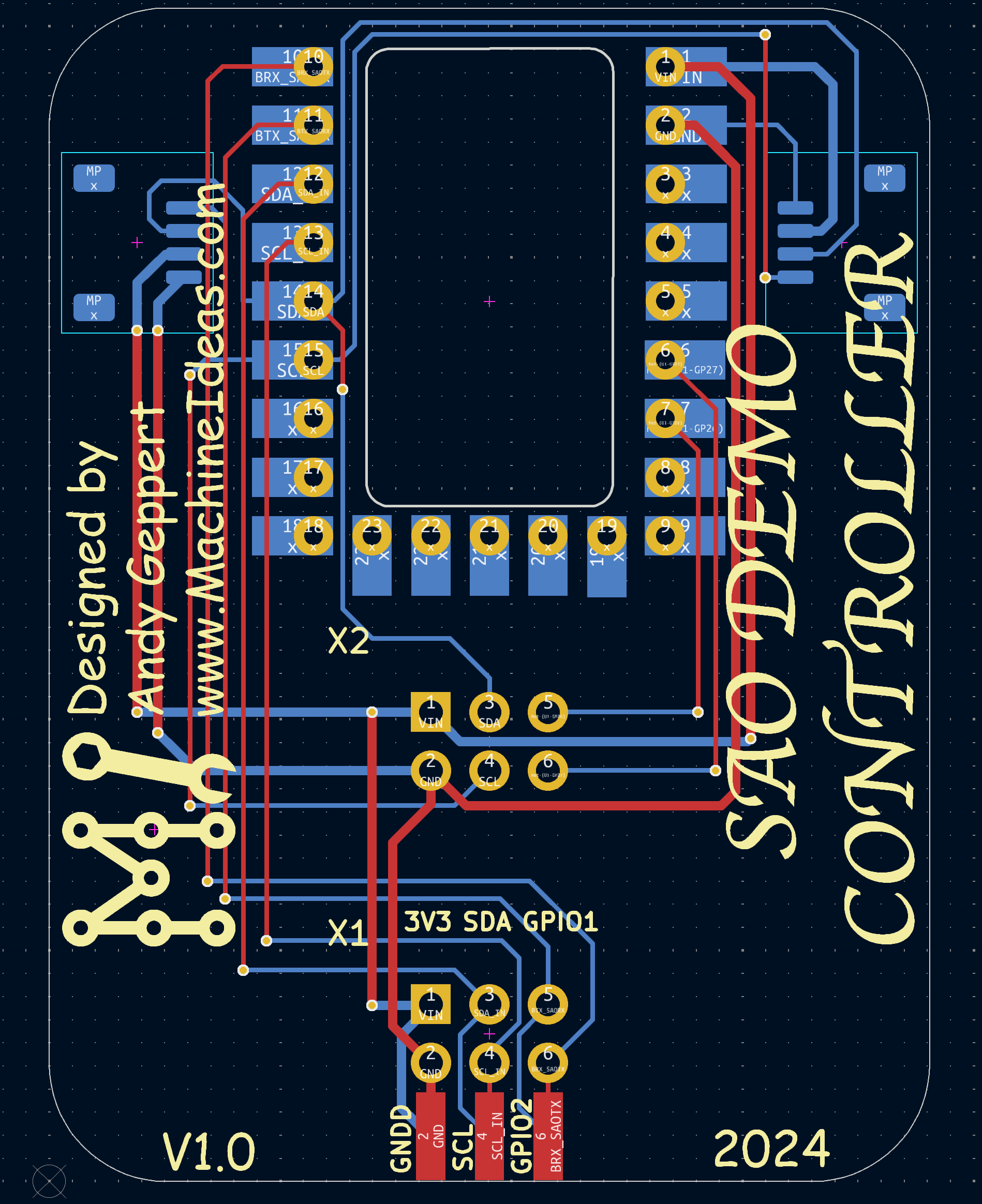
Routing is refreshingly simple:
![]()
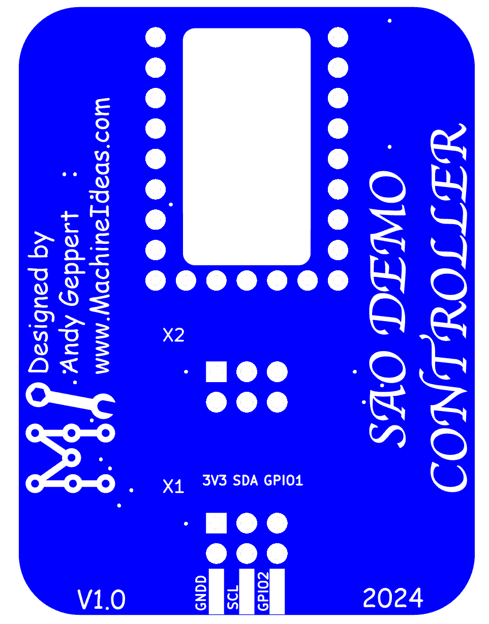
And here's a render in blue to try and match the RP2040-Zero board:
![]()
Click. Click. Ordered!
-
How am I going to control this advanced SAO?
10/03/2024 at 02:41 • 0 commentsWith the Supercon 2024 SAO Contest in full-swing, and more ideas than time... how am I going to control these SAOs that are designed to utilize I2C without having a badge pre-programmed?
With an intermediate SAO brain, of course! There are so many good microcontroller choices. The ESP32 options are compelling with Wifi and BT built-in. But since we know the badge is going to be based on a Pico W, the RP2040-Zero will be in this SAO Demo Controller.
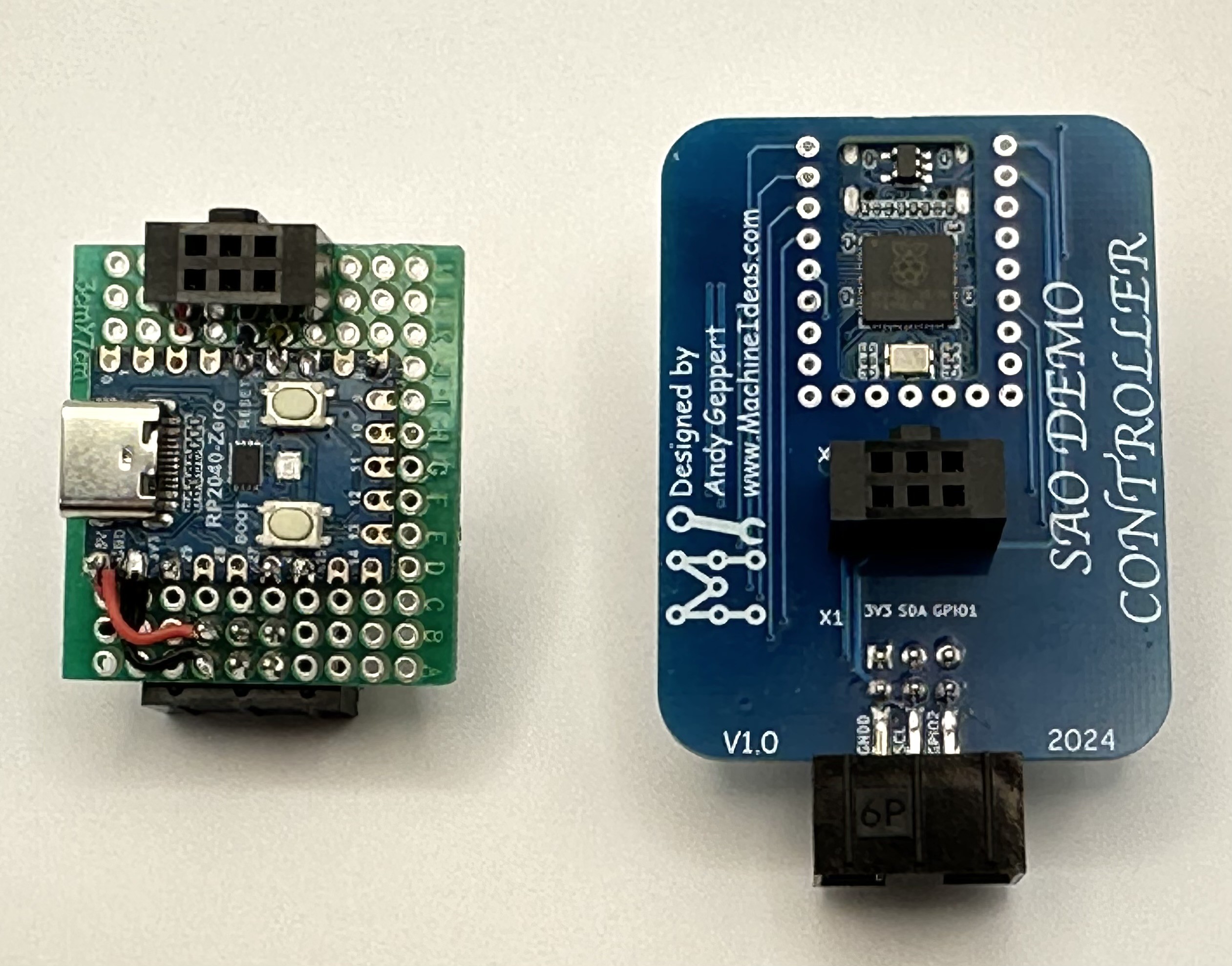
Here is my first proof of concept, powered and programmed through the USB-C port:
![]()
And here it is being powered by one of my most favorite badges:
![]()
Now that the concept is proven, time to whip up a little design in KiCAD....
SAO DEMO Controller
A small inline SAO with an RP2040 used to demo SAOs that require smarts, but do not have it built-in.