Close
0%
0%

SAO DEMO Controller

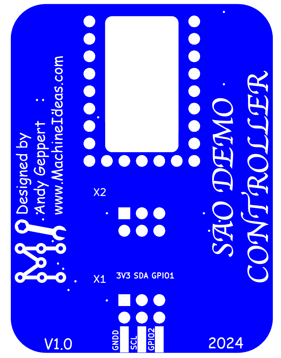
A small inline SAO with an RP2040 used to demo SAOs that require smarts, but do not have it built-in.

Similar projects worth following
The SAO Demo Controller makes it convenient to bring life to your advanced I2C-based SAO! Use this to test and demonstrate your new design even when your host badge isn't ready to control the SAO.

It also brings a right-angle connection of an SAO to your badge host, as a bare PCB.

With the RP2040-Zero installed, you get drag-n-drop simplicity for easy sharing of demo programs and compatibility with the Supercon 2024 badge. You also get reset and boot buttons, and a USB-C programming and power connection. And, of course, you can still access all the pins of the RP2040-Zero for complete hackability. Includes RGB LED too!

V1 CAUTION: Do not plug this into your host badge and USB-C at the same time, and make sure your SAO is 5V tolerant!!!

V2 fabrication is underway. See details section below.

BONUS: Demotes your badge to be "just a battery pack!"
BONUS 2: Consider using it as a logic analyzer with https://github.com/pico-coder/sigrok-pico

As of this writing, the Supercon Add On Challenge is underway, emphasizing I2C functionality in SAOs. There is an inherent need to control these advanced SAOs. Ultimately, the goal is to control the SAOs from the Supercon badge as the host. However, there are two intermediate needs to avoid having a dark and motionless SAO on your badge.

A) The need to demonstrate what our SAOs are capable of.

B) The option to use the SAO without creating firmware on every badge you want to use the SAO with.

To meet those two intermediate needs, this project was conceived with three simple elements:
1) An SAO plug to secure to a badge and draw power.
2) An RP2040-Zero microcontroller breakout board to control the downstream SAO.
3) An SAO socket, to supply power and control to your SAO.

The drag-n-drop simplicity of the RP2040 makes it easy to access demo programs and keeps the demos compatible with the Supercon 2024 badge. You also get reset and boot buttons, and USB-C.

Features of the SAO Demo Controller V1:

  • Dual SAO plug mounting option. Option to connect the SAO plug header vertically (edge) or horizontally.
  • Right-angle pass-through adapter. Use it the bare board as a right angle adapter for your SAO, with pass-through functionality.
  • Connect I2C accessories. Add one or two QWIIC/STEMMA QT sockets to leverage those broad I2C ecosystems.
  • Experiment with the RP2040-Zero as an accessory to your badge via I2C or UART.
  • The RP2040-Zero has a built-in RGB to use for status indication and dazzling.

The SAO Demo Controller V2 changes:

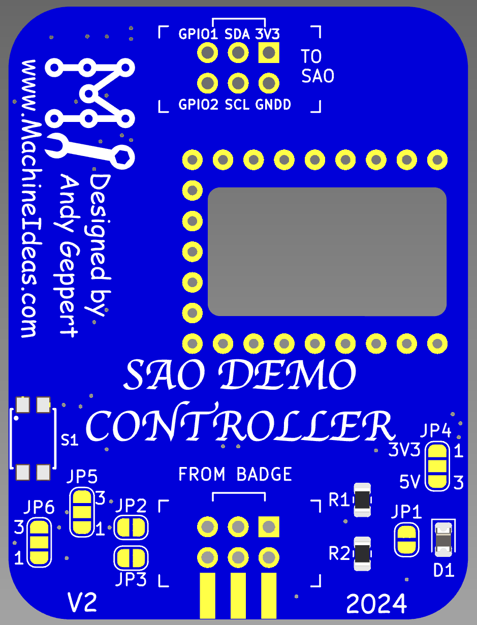
  • SAO output moves to the top edge to make it easy to access the back of our SAO while still plugged into the demo controller. This helps with bring-up of your SAO.
  • The RP2040-Zero moves to the front face of the board for easy access to it's buttons and RGB LED.
  • Power management is improved with a diode to block current flowing from the USB C port of the RP2040-Zero back into the badge.
  • Default voltage to downstream SAO is now 3.3V provided by the RP2040-Zero. A solder jumper is available to change downstream SAO power source to be VIN/5VUSB, if needed.
  • Downstream SAO (and QWIIC) port GPIO1 is selectable as GP1 or 26, GPIO2 as GP0 or 27 to improve compatibility with different SAOs that my brother and I are working on.
  • Downstream SAO GPIO1 and 2 can be pass-through from the badge SAO port with solder jumpers.
  • Added a button to control RP2040-Zero (mode selection, if desired).
  • Added a voltage divider to measure incoming power with RP20240-Zero.
  • Renumbered RP2040-Zero symbol/footprint to match Waveshare documentation.


Connect to all the things and test your Badge's batteries:
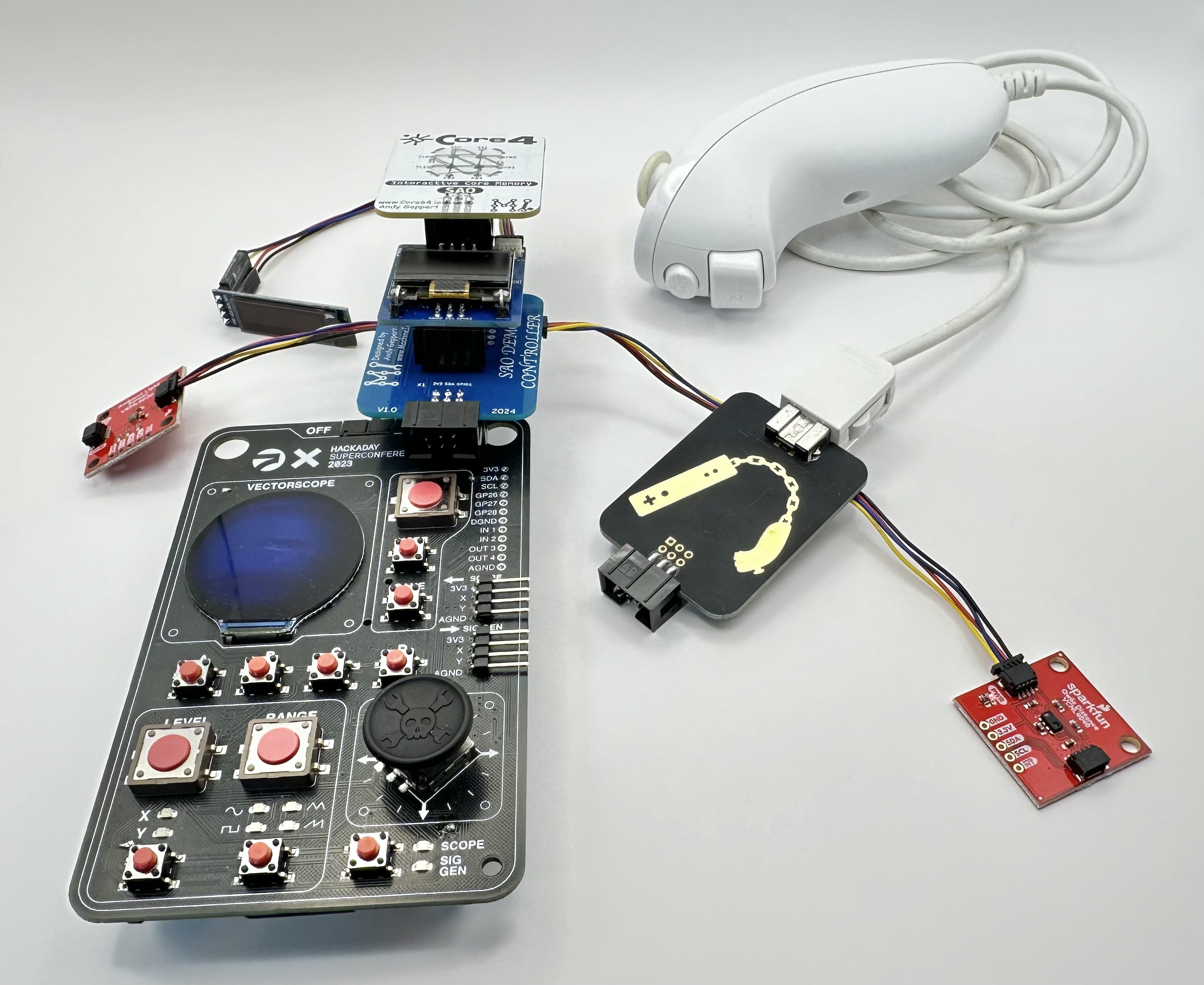
Demo your SAO:
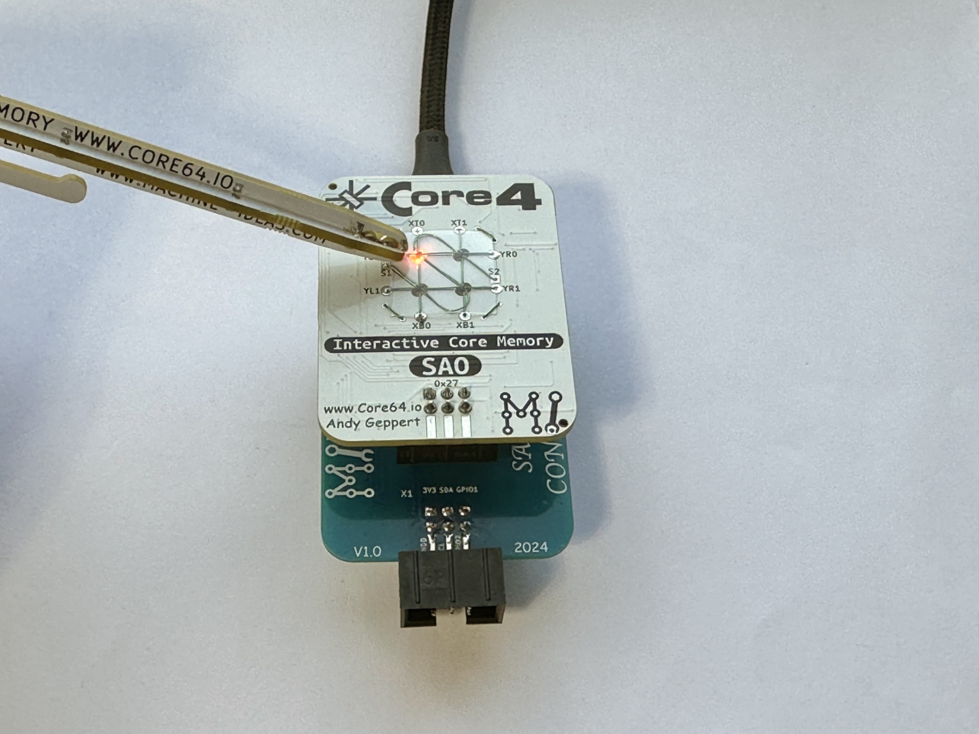
Mount your SAO perpendicular to the badge:

Access the RP2040, USB-C, Boot, Reset and QWIIC ports on the back:

Connect to one thing:
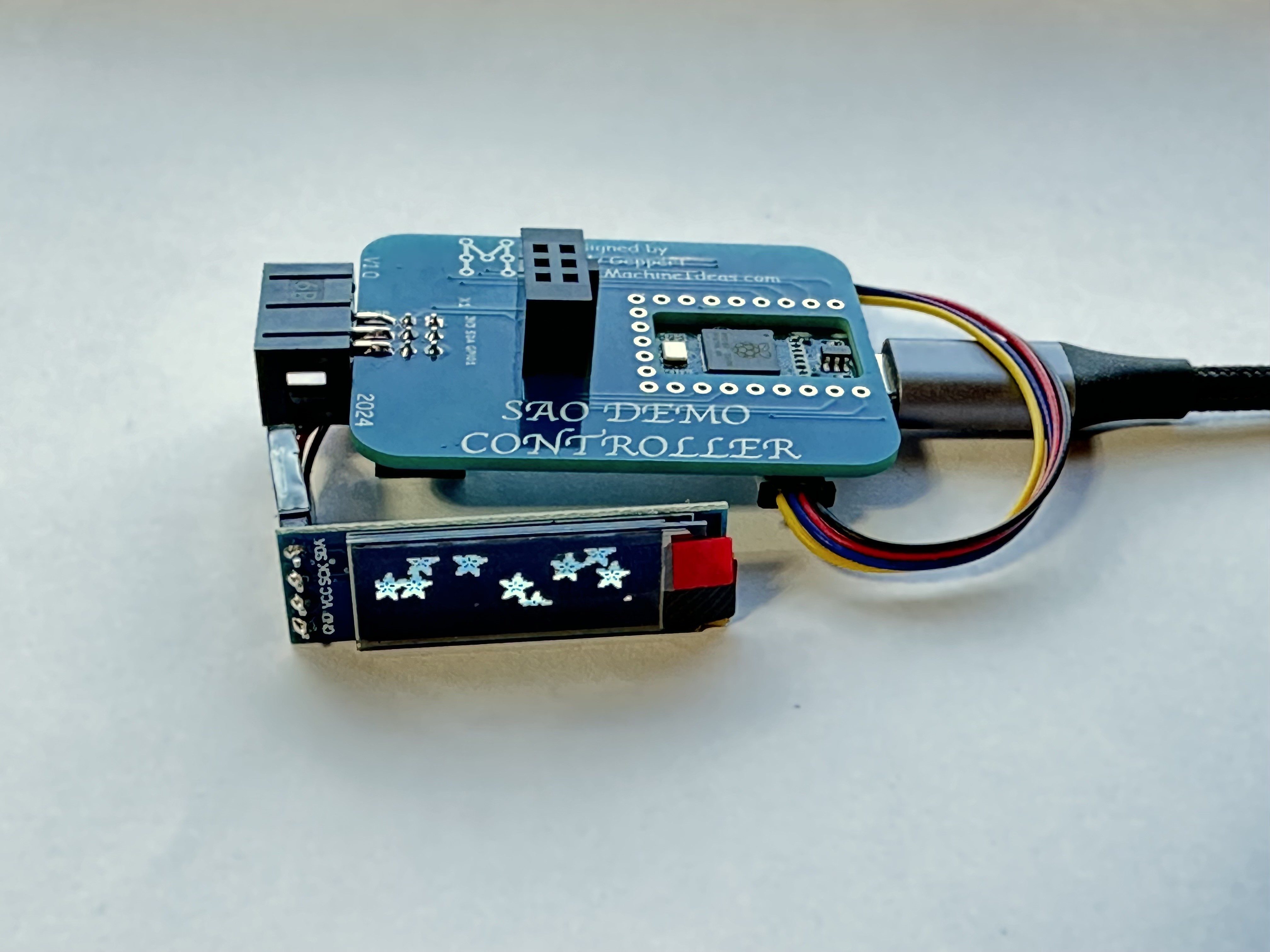
Is it a badge or is at an SAO?
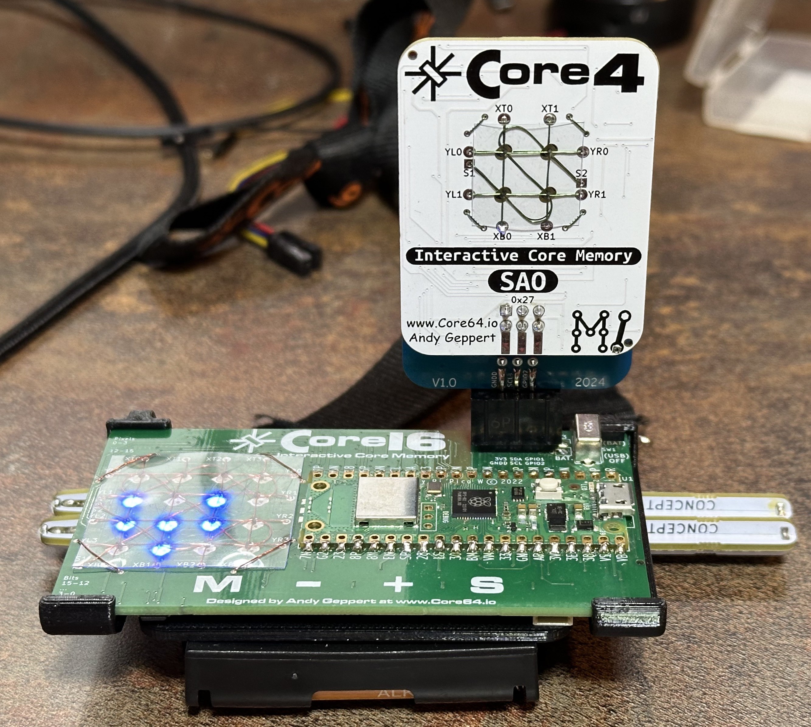
I'm deep in the work of SAO testing, and the SAO Demo Controller is very helpful.

SAO_Demo_Controller V2 Schematic.pdf

SAO Demo Controller V2 Schematic

Adobe Portable Document Format - 874.35 kB - 10/29/2024 at 02:15

Preview

SAO Demo Controller V1 Schematic.pdf

SAO Demo Controller V1 Schematic

Adobe Portable Document Format - 141.11 kB - 10/04/2024 at 03:15

Preview

  • 1 × SAO Demo Controller PCB
  • 1 × https://www.waveshare.com/wiki/RP2040-Zero
  • 1 × SAO Shrouded Header 2x3
  • 1 × SAO Socket 2x3
  • 2 × QWIIC/STEMMA QT Socket

  • SAO Demo Controller V2 Design Improvements

    Andy Geppert10/22/2024 at 13:41 0 comments

    After some hands on experience with V1, I've decided to enhance the design and squeeze in another round of boards before Supercon. These are all feature additions which preserve V1 functionality. Front side:

    The changes are:

    • SAO output moves to the top edge to make it easy to access the back of our SAO while still plugged into the demo controller. This helps with bring-up of your SAO.
    • The RP2040-Zero moves to the front face of the board for easy access to it's buttons and RGB LED.
    • Power management is improved with a diode to block current flowing from the USB C port of the RP2040-Zero back into the badge.
    • Default voltage to downstream SAO is now 3.3V provided by the RP2040-Zero. A solder jumper is available to change downstream SAO power source to be VIN/5VUSB, if needed.
    • Downstream SAO (and QWIIC) port GPIO1 is selectable as GP1 or 26, GPIO2 as GP0 or 27 to improve compatibility with different SAOs that my brother and I are working on.
    • Downstream SAO GPIO1 and 2 can be pass-through from the badge SAO port with solder jumpers.
    • Added a button to control RP2040-Zero (mode selection, if desired).
    • Added a voltage divider to measure incoming power with RP20240-Zero.
    • Renumbered RP2040-Zero symbol/footprint to match Waveshare documentation.

    Backside:

    Now I need to add a switch, 2 resistors, and a diode to the kits!

  • DHL is here!

    Andy Geppert10/03/2024 at 03:26 0 comments

    I sure do like seeing that yellow truck show up these days!

    Out with the old, in with the new:

    Will it work?

    YES! Now I can get on with development and troubleshooting the new Core4 that just showed up as well. This capability is going to be very convenient for the other SAOs I'm working on!

    I'm really glad I added the QWIIC/STEMMA ports. Those ecosystems have a lot to offer, including pre-made wiring and wire-to-breadboard options. Check 'em out:

    https://www.sparkfun.com/qwiic

    https://learn.adafruit.com/introducing-adafruit-stemma-qt/what-is-stemma

    There are many screens and sensors to experiment with.

  • KiCAD Copy and Paste

    Andy Geppert10/03/2024 at 03:13 0 comments

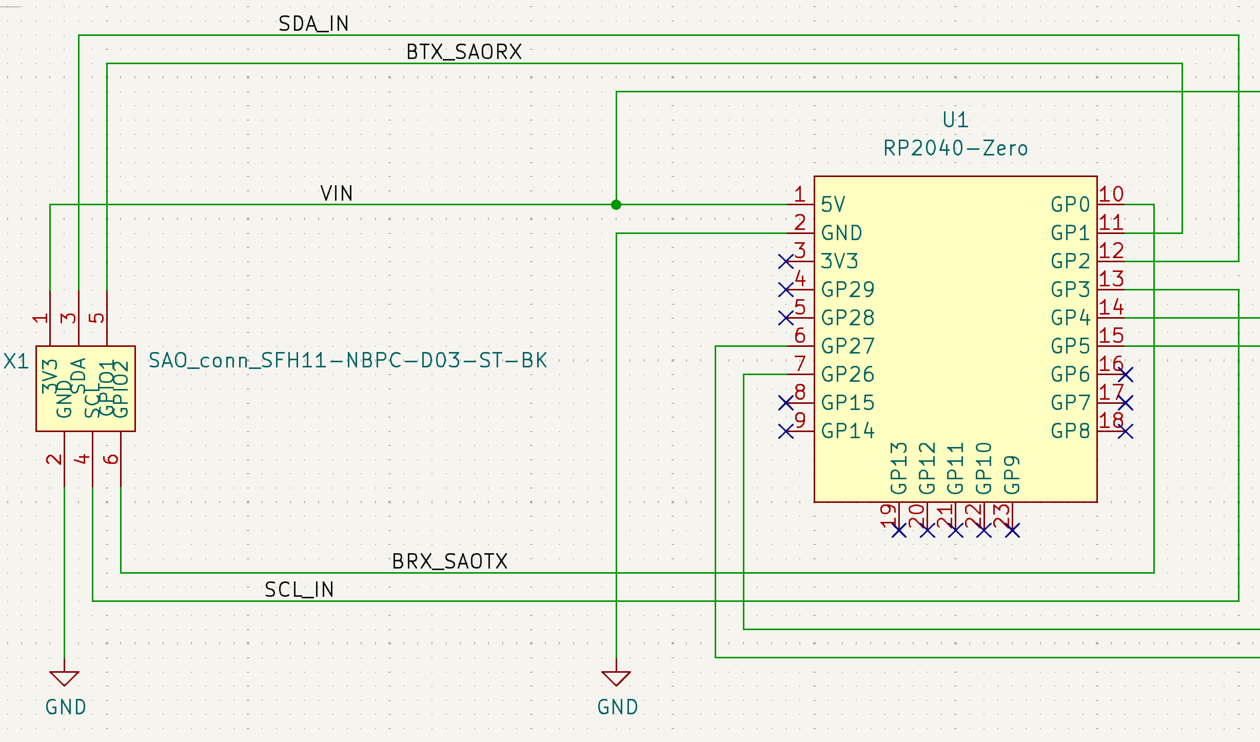
    Starting with an existing SAO project makes this project pretty quick to spin up. From a schematic perspective, it looks like everything is passive, with just five footprints to place.

    All I need from the badge which is the power host, are two of the size SAO pins. But I hate to leave pins unconnected, and I have use case brewing that will help me prototype another SAO, so here is how I plan to use all size pins of the host side SAO connection:

    I'll route the I2C into a spare I2C port of the RP2040 so I the RP2040 can be configured as a slave on the badge I2C Bus. By doing this, the RP2040 can become an advanced I2C device, and control several other things down stream. Such as: a SPI device, analog in/out, another I2C bus, or expanded GPIO. I'm considering this for my Etch sAo Sketch that would use an ePaper display, which only come in the SPI variety as far as I know. Having this capability in the SAO Demo Controller will let me experiment with the concept.

    And if that proves to be too difficult (it's certainly not trivial if I want true bidirectional I2C behavior), by Plan B for that project is to use the GPIO of the SAO port as a UART, with the RP2040 translating simple UART commands into SPI control for the ePaper.

    Both of these pin pair usages are not core to the SAO Demo Controller, but I feel better connecting those pins to the RP2040, and letting them be ready for possibilities yet to come.

    The downstream side will be configured like this:

    This allows your to configure the RP2040 to drive the default I2C bus and communicate with your downstream SAO, and optionally, two QWIIC/STEMMA ports for testing break-out boards and accessories.

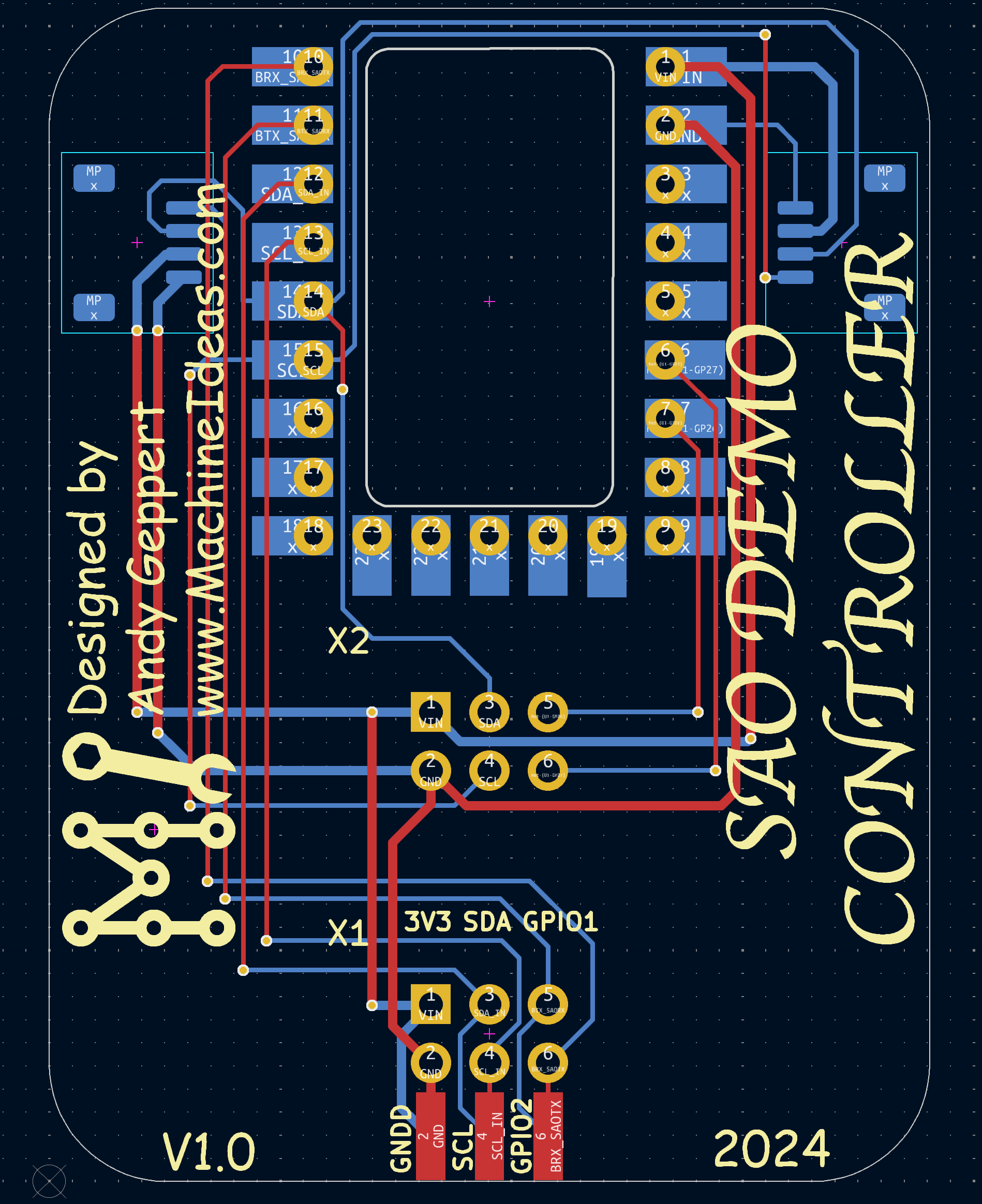
    Routing is refreshingly simple:

    And here's a render in blue to try and match the RP2040-Zero board:

    Click. Click. Ordered!

  • How am I going to control this advanced SAO?

    Andy Geppert10/03/2024 at 02:41 0 comments

    With the Supercon 2024 SAO Contest in full-swing, and more ideas than time... how am I going to control these SAOs that are designed to utilize I2C without having a badge pre-programmed?

    With an intermediate SAO brain, of course! There are so many good microcontroller choices. The ESP32 options are compelling with Wifi and BT built-in. But since we know the badge is going to be based on a Pico W, the RP2040-Zero will be in this SAO Demo Controller. 

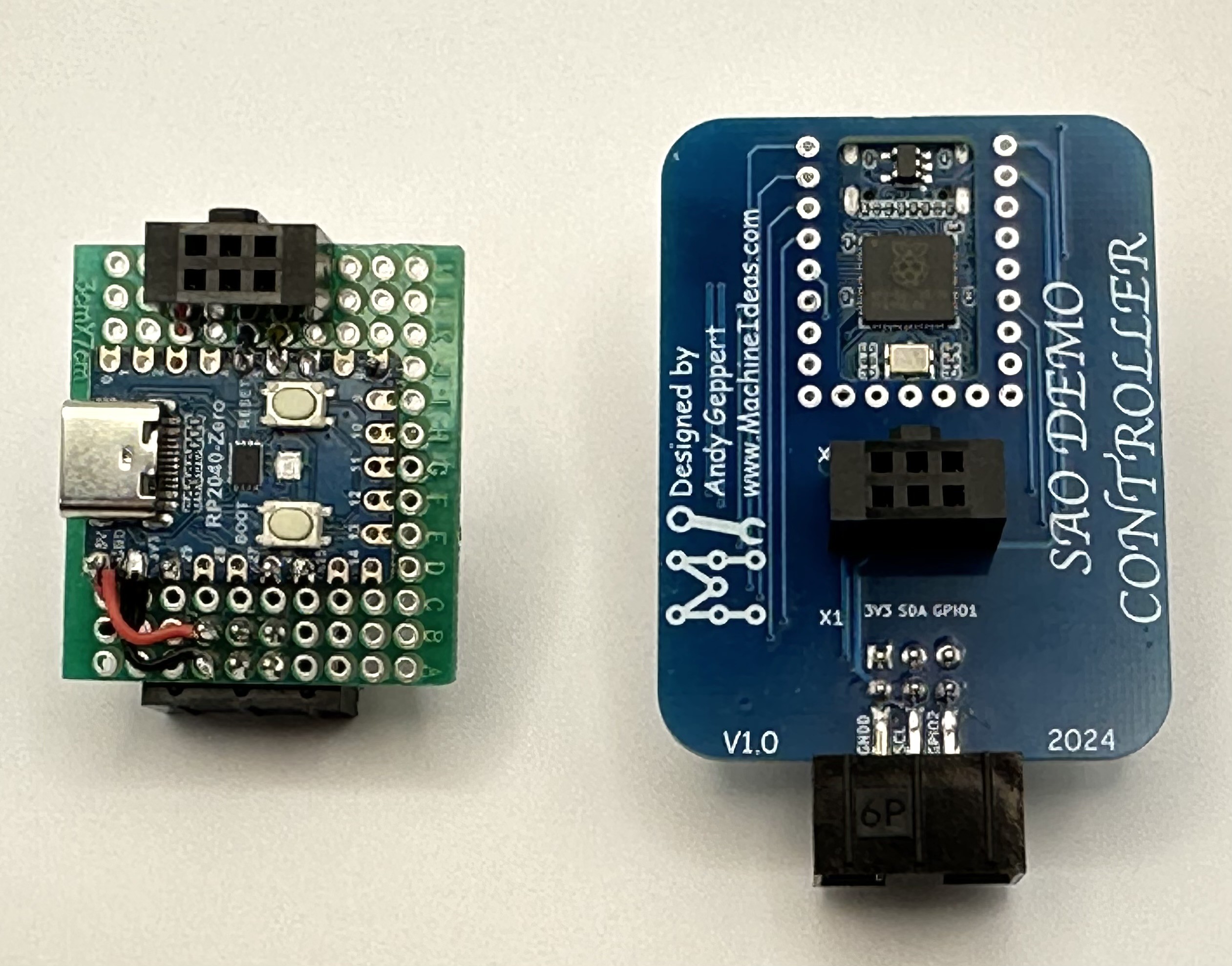
    Here is my first proof of concept, powered and programmed through the USB-C port:

    And here it is being powered by one of my most favorite badges:

    Now that the concept is proven, time to whip up a little design in KiCAD....

View all 4 project logs

  • 1
    ​Gather the components

    CAUTION: Do not connect USB-C power to the SAO Demo Board when it is connected to a host Badge. This will inject 5V into your badge's 3.3V SAO Power Bus.

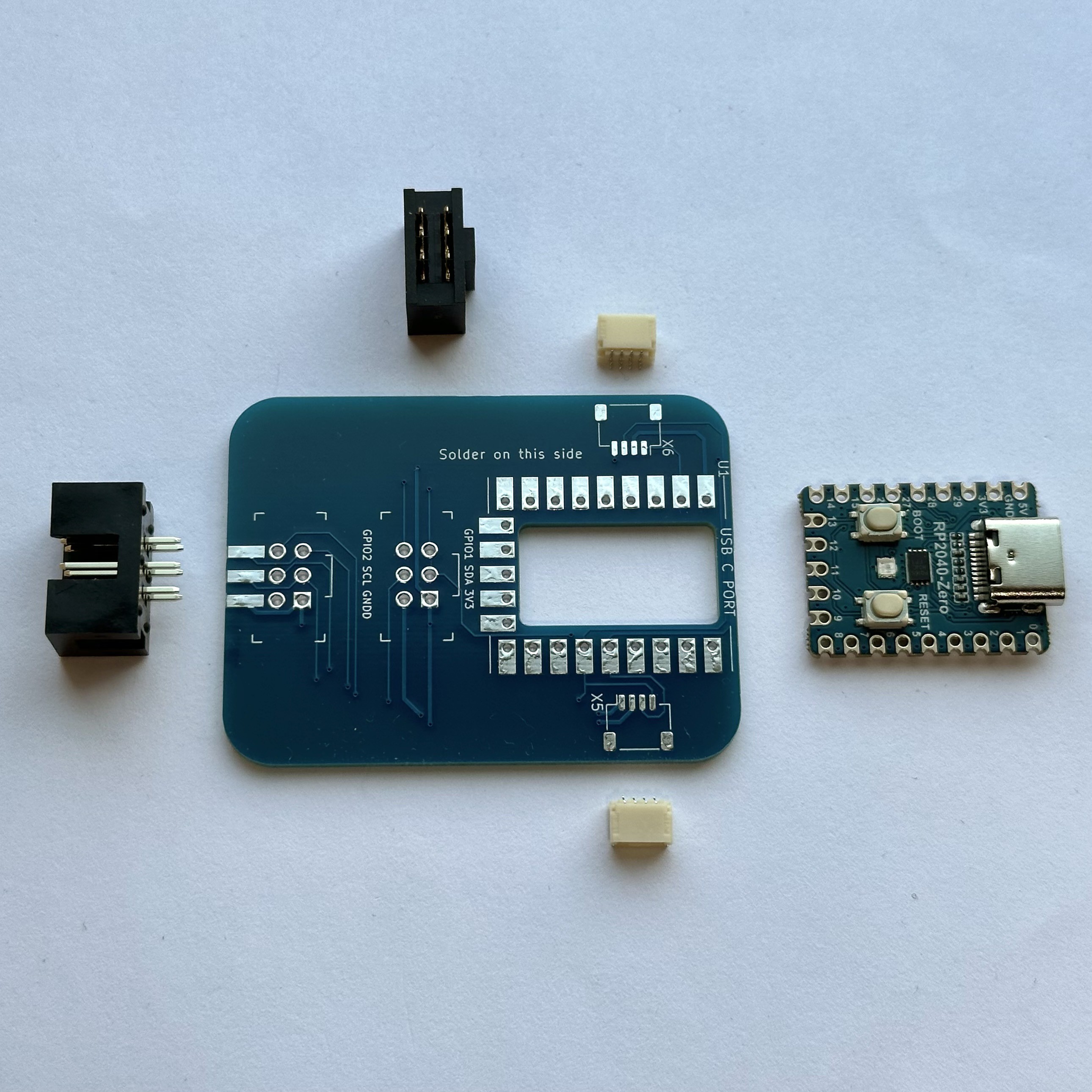
    Contents of the kit:

    1. SAO Demo Controller PCB (right side of this image)
    2. RP2040-Zero Microcontroller (center)
    3. SAO Header, shrouded male pins (left side of this image)
    4. SAO Socket, female socket (top of this image)
    5. A pair of QWIIC/STEMMA sockets (white)
  • 2
    Solder on the QWIIC/STEMMA sockets

    Tin one of the larger square pads of X5 or X6.

    Keep the solder hot and slide the connector into alignment with the other pads.

    Remove the solder pencil after the connector is positioned, and don't move the connecter while the solder cools, or afterwards. If you have to reposition the connector, reheat the first solder pad, then carefully adjust the connector position. If you apply force to the connector with only one solder joint, you risk tearing the solder pad off.

    Solder the other square pad on the opposite side of the connector.

    Then solder the four pins.

    Repeat for the second connector.

  • 3
    Solder on the RP2040-Zero

    The RP2040-Zero is installed with the USB-C port towards the outer edge of the main PCB, with the buttons facing up, on the backside of the main PCB which says "solder on this side."

    Align the RP2040-Zero by borrowing your friends' spare 0.100" header pins.

    Solder the castellated edges of the RP2040-Zero to the base PCB.

View all 5 instructions

Enjoy this project?

Share

Discussions

todd.krein wrote 10/09/2024 at 19:50 point

Perhaps I'm just blind, but is this kit available somewhere?

  Are you sure? yes | no

Andy Geppert wrote 10/10/2024 at 02:06 point

Sorry about that - it should go live on Tindie in the next 24 hours I hope: https://www.tindie.com/products/machineideas/sao-demo-controller-v10/

  Are you sure? yes | no

davedarko wrote 10/02/2024 at 08:51 point

There's an RP2040-tiny board out there, that has USB and the two buttons on a separate board, which makes the tiny be surface-mountable. That's what I chose for the #TARS SAO 

  Are you sure? yes | no

Andy Geppert wrote 10/02/2024 at 13:15 point

Oh cool. I hadn't seen that variant that you used. Looks like I'm using the cousin of the RP2040-Tiny, the RP2040-Zero https://www.waveshare.com/wiki/RP2040-Zero

  Are you sure? yes | no

Similar Projects

Does this project spark your interest?

Become a member to follow this project and never miss any updates