Close
0%
0%

Solar Energy Generator

A solar energy system up to 500W in power for use with lithium batteries.

Similar projects worth following
This platform is designed to be used as a power supply for systems that do not have access to grid power or for taking systems that are normally grid connected off of the grid. Currently it is in a development stage, and circuit blocks have been constructed separately for to make development and testing more manageable.

Some Target applications include:
- LED street lights and security lights
- Weather and sensor stations
- Radio relays and mesh network nodes
- Security cameras and sensors
- Power for sailboats and cabins

General Features:
- Supports panels in series or parallel combinations up to 500W.
- Compact size of 120x120x45mm.
- Dual phase converter allows for currents up to 16A, input FETs and internal rails tolerate input voltages up to 50V.
- Maximum Power point tracking across all temperature and insolation conditions maximizes energy output.

Link to the full System Design Document can be found here:

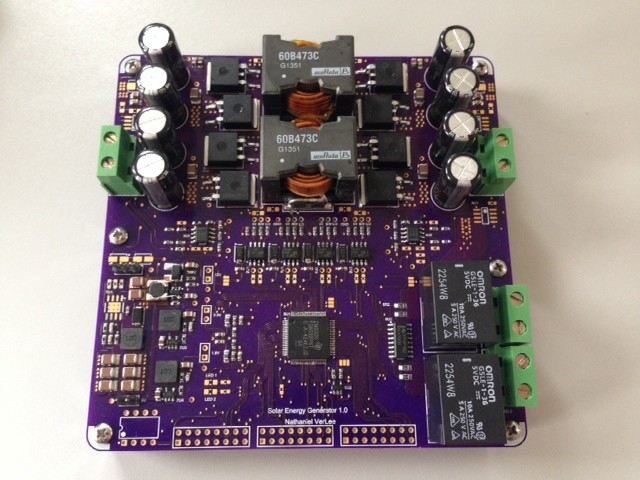
The solar energy generator has a buck boost topology DC-DC converter that can either step up or step down the output voltage from the input voltage, which allows the system to operate at the panels peak efficiency known as the maximum power point. The maximum power point is tracked using a current and voltage sensor by periodically changing the input to output voltage relationship of the DC-DC converter and measuring the corresponding changes in output power the sensors. In addition to implementing Maximum Power Point Tracking, the buck boost topology allows the battery operating voltage range to be either higher, lower, or both relative to the panel input voltage depending on the solar panels used. When configured properly it can be used to harness the energy of panels up to 500W in capacity. Batteries capacities can be anywhere from 100 watt hours to a few kilo-watt hours in capacity, and the initial target battery chemistry is lithium iron phosphate due to its high cycle life and increased safety over traditional lithium cells. Other chemistries such as lead acid will also be supported in the future. The generator is composed of the following circuit blocks: a two phase buck boost DC-DC converter, a battery current sensor, a load current sensor, a battery voltage sensor, gate drivers for the converter, a C2000 micro controller, 12V, 5V, 3.3V and 1.8V rails, and a load switch.

A load switch is critical to protecting the battery from over discharge and short circuit. The load switch opens and disconnects the load if either of these conditions should occur. Currently, this portion of the system is not fully defined and may be implemented either with relays or MOSFETs as the switch. Each of the two load switches should be able to handle at least 10A, and more may potentially be added externally.

A Texas Instruments C2000 TMS320F28035 has been selected for the final design of the project, but in the prototyping stage a TMS320F28027 is being used as it is available in a pre made "launchpad" platform from TI, which includes the necessary debugging and programming interface as well as 5V and 3.3V supplies. The C2000 microcontroller was selected because it has many features designed for digital power applications, and configuring it to drive the buck boost converter is not only easy, but powerful, allowing multiple converters to be driven in a phase relationship, and allowing for fast shut down of the converter stage in the event of a dangerous transient event. In the final single-PCB solution, a buck converter will be connected to both the panel input and the battery via a diode or, which will source power from the higher of the two voltages. This 5V rail will then supply power for a 12V rail (boost) for the FET gate drivers and the 3.3V and 1.8V rails for the micro, sensor circuits, display, and various other circuits.

Finally, the converter will include a simple character display, buttons and an encoder wheel to configures various system settings such as battery float voltage, power limiting, a load shutdown timer, display system power output, and allow for future information and configuration features. I selected an OLED display from Adafruit for its high contrast and bold appearance.

In the current stage of development the separate sensor boards, power stage board and the C2000 development board are all connected to each other in a manner very similar to the configuration of the final completed PCB. Some features are not currently available such as the load switches and the supply rails. Much of the last two months of development has been teaching myself to code for the C2000 platforms. The next stages of development will include finalizing the proof of concept with separate interconnected PCBs, finishing work on the final PCB, measuring the performance of the prototype with instruments and searching for possible improvements, and creating in depth documentation of the project. 

Link to the full System Design Document can be found...

Read more »

Solar Energy Generator Layout Diagram.pptx

presentation - 624.99 kB - 10/30/2016 at 15:02

Download

Solar Energy Generator Layout Diagram.jpg

A diagram of the layout of the enclosure assembly for prototype testing

JPEG Image - 141.85 kB - 10/30/2016 at 15:02

Preview

Solar Energy Generator System Design.pdf

Overview of the system design for this project

Adobe Portable Document Format - 739.00 kB - 10/30/2016 at 15:02

Preview

Solar Energy Generator R1.1 BOM.xlsx

Bill Of Materials

sheet - 34.68 kB - 10/30/2016 at 15:02

Download

Solar Energy Generator R1.1 SCH.pdf

Schematic

Adobe Portable Document Format - 862.64 kB - 10/30/2016 at 15:02

Preview

  • 1 × TI TMS320F28035 Microprocessors, Microcontrollers, DSPs / Microcontrollers (MCUs)
  • 2 × Coilcraft VER2923 Inductors, Chokes, Coils and Magnetics / Fixed Inductors, Chokes and Coils
  • 4 × IRF IRS21867 Low and High Side Gate Driver IC
  • 3 × Allegro ACS722 Hall Effect Current Sensor
  • 2 × TI OPA2317 Precision, Low Offset Op-Amp, for Voltage Sensing

View all 16 components

  • On to the Next Rev, A code update

    Nathaniel VerLee04/08/2015 at 00:07 0 comments

    I have been digging through lots of TI literature on how to use their libraries to control my solar generators power conversion hardware. This is a fair amount of new code territory for me as the way the write these algorithms its all in optimized assembly to reduced the number of processor cycles needed for running these algorithms. I am going to be working towards a goal of simply regulating the output voltage of the converter, and then from there will move on to implementing a more advanced version of a "perturb and observe"MPPT algorithm.

    In other news I have started reworking the board with fixes to many of the bugs I have found and changes to many of the components I am using. I will be doing a bit of cost reduction and component optimization along the way, and have gotten ride of a few things, mainly the 5V rail. I am hoping to get the next revision out in a month or two, but there is still plenty I can do with the hardware I have now.

  • More Coding Progress

    Nathaniel VerLee02/11/2015 at 14:54 0 comments

    I have been getting a good sense of how I am going to write the firmware for this project, with three basic timer loops that run high priority/frequency, medium priority and low priority tasks. Examples of higher priority tasks will be ADC sampling, power computation, MPPT and voltage regulation algorithms, and some examples of lower priority tasks would be updating the display and responding to button pushes, changing the state of the charging algorithm, and turning on and off loads. The next big tasks will be to write a voltage regulation algorithm and potentially integrate it into the MPPT algorithm, as well as getting a battery charge algorithm to begin testing with.

    On the hardware front I have started to compile a long list of upgrades and changes to make to the next board revision, and I hope to get working on the next board once I prove out the current hardware.

  • I Blinked an LED today

    Nathaniel VerLee12/31/2014 at 20:36 0 comments

    Which Personally, I consider a significant accomplishment. It has been awhile since I wrestled with configuring the compiler for a specific device and It took some doing to get my projects working with the new device. I am more of a hardware person, can you tell?

  • Communication Success!

    Nathaniel VerLee12/30/2014 at 14:12 0 comments

    After fixing some pullup/pull down and properly connecting the JTAG programming wires, I have successfull gotten code composer to talk to this new micro, so the next step be to port my code over to the new micro (Now the C2000 TMS320F28035, Previously the TMS320F28027 for the prototype). I will probably start with a blinking LED "hello world" and then start trying to get the micro to read from the sensors and switch the FETs.

  • Finally Testing the new Board

    Nathaniel VerLee12/29/2014 at 17:26 0 comments

    After assembling one of the three boards I had fabricated, I have finally gotten a chance to start testing. A new job and move process has put a lot of my side projects on hold and I am finally getting the chance to return to this project. The first step was to verify that the 1.8, 3.3, 5 and 12V rails were working properly. I made a silly mistake with the 12V boost converter: I entered the schematic as if it was a buck. It was an easy enough rework to do with a piece of kapton and some wires. I also made the easy mistake of getting the wrong IC package for the TPS54360 that I am using for the 5V buck converter. After I got all the rails up and working I moved on to connecting them to their respective loads and discovered a lovely dead short on the 3.3V rail (on the digital side). The 3.3V supply powers two rails - an analog and a digital one. Each is isolated from the other via a Pi filter, which is a kind of cap-ferrite-cap arrangement designed to prevent noise created by pulsating digital currents from the micro from propagating into the analog instrumentation circuits. It was the digital rail that appeared to be shorted, and after removing the micro this proved to be the case. After thoroughly inspecting this rail there are no visible mistakes in the layout files, and since most of these traces are in one of the midlayers I can only assume that they became shorted because I got too close to a manufacturing tolerance. In any case it was easy enough to rework, and the next steps will be to start getting code on the micro and get the buck stages up and running. From there I will be tweaking the voltage and current measurement circuits (they probably need a low pass with a steeper roll off) and trying to write a basic 3 stage battery charging algorithm.

  • About time for an update... Board is here!

    Nathaniel VerLee11/04/2014 at 18:23 0 comments

    It has been awhile, but the boards came about two weeks ago and I started assembling them. Here is the first sone below. You can already see in the middle left area there is a silly mistake... oops. Kinda forgot that was a boost, not a buck, when I was doing the schematic capture. I havent found any show stoppers though. As I am in the middle of moving I have not had much time to start testing and validations of the circuits. As soon as I get my lab equipment set back up im hoping to do just that.

  • Project Rendering Added

    Nathaniel VerLee09/29/2014 at 03:02 0 comments

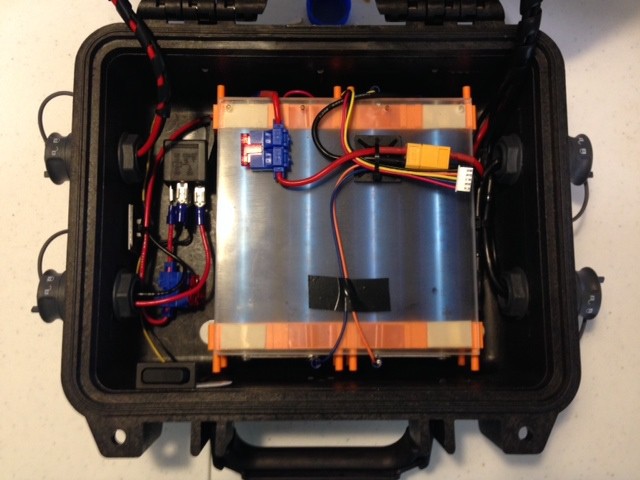
    Its not quite an artists concept, but I think it does an ok job of illustrating the point. Here is a photo of the actual case that I have, and have been using with a 150WHr battery, albeit with a charge controller that I purchased. You can see the waterproof circular connectors on the case and wiring, load relay, and in-line fuses in this photo. I plan on changing the connectors out with Souriau UTS connectors - I don't really care for how the current Bulgin 6000 ones mate. My new PCB will eventually be assembled and eventual put into this case as a test platform. 

  • Schematic and BOM Added

    Nathaniel VerLee09/28/2014 at 23:41 0 comments

    I have added a schematic and BOM here. While you can see some of the main components used in the component listing on Hackaday.io, the full BOM and schematic can be found at that link. 

  • PCB is finally done!

    Nathaniel VerLee09/27/2014 at 21:43 1 comment

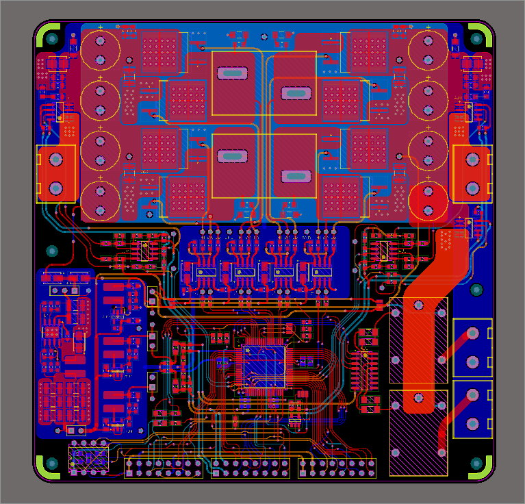
    Admittedly, I spent a bit too much time on this board - I wanted it to be perfect. I know there will need to be another revision before its ready to be called "done" but I wanted to give the first run my best effort. This has pushed me behind in terms of continuing to work on software, and before I do focus back on the software there will be a big push to finalize the materials needed on my BOM. 

  • Update on PCB, and a side project...

    Nathaniel VerLee09/15/2014 at 12:16 0 comments

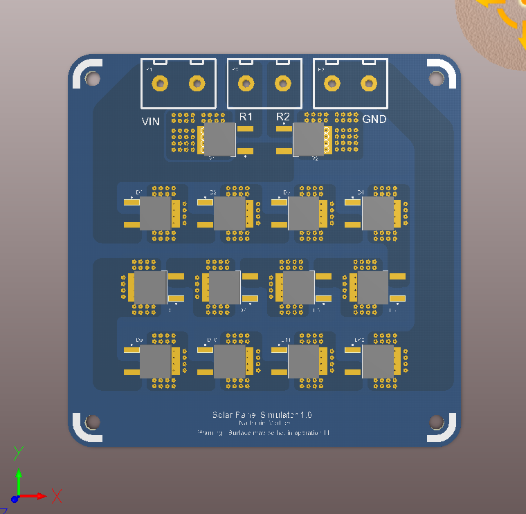
    I have been hard at work routing the final PCB, and its coming out quite nicely. It doesn't look a whole lot different from the photo I previously posted because most of the work has been routing, and the placement was mostly finalized. The final design should go out tonight. In addition, I had a nice little distraction that has already been sent off to OSH park. This "Solar Panel Simulator" is a rather simple way to turn a power supply (which must be capable of doing CC limiting) into a panel simulator. The concept is rather simple: you hook it up in parallel with the supply, set in CC mode, and the thing you want to power (my project) and the power supply now appears to the load to have the V-I characteristic of a solar panel. The diodes basically act as a shunt and sink all the current when the load is not drawing anything. This will be very useful for all those cloudy days and late nights that I have wanted to test my system in accurately simulated conditions. 

View all 16 project logs

Enjoy this project?

Share

Discussions

Nathaniel VerLee wrote 10/23/2020 at 20:46 point

Would people be interested in seeing a version 2 of this project? Would you be interested in using one and programming one if it was based on MSP430? Let me know!

  Are you sure? yes | no

AVR wrote 10/23/2020 at 21:30 point

100% I would and I think the rest of us would agree!

  Are you sure? yes | no

jo wrote 01/03/2017 at 19:23 point

What a brilliant and awesome project, thats impressive 

  Are you sure? yes | no

Nathaniel VerLee wrote 10/30/2016 at 15:15 point

Long overdue update - files are back up but now hosted on the hackaday site.  I do intend to eventually do another revision of this project, but it may be awhile. Stay tuned. 

  Are you sure? yes | no

mdombros wrote 10/09/2016 at 18:40 point

Is this project still active? I'd really like to see more details but as the previous user commented, the main website is down.

  Are you sure? yes | no

George I Fomitchev wrote 08/12/2016 at 16:08 point

amazing... we just made a simple charger... not as advanced as yours..

  Are you sure? yes | no

cmduarte wrote 12/28/2015 at 16:57 point

It appears that your website has expired. I would like to see the details on this project.

  Are you sure? yes | no

morozaw wrote 08/25/2015 at 13:56 point
HiNathaniel,

Could You reupload full System Design Document? Link is dead :(

Cheers!

  Are you sure? yes | no

Tachyon wrote 09/29/2014 at 07:41 point
This looks awesome and I can't wait for it to reach completion. I'll be following along eagerly.

One comment/ request. Given the example use cases as well as my personal experience, I'd like to request support for NiFe batteries as they are THE most bullet proof, long lasting( in the usable lifetime sense) battery chemistry around.

  Are you sure? yes | no

matt venn wrote 09/28/2014 at 11:43 point
Hey well done for getting to the finals!
I'm interested in the dc/dc topology. Do the fets work as diodes too? I suppose that must be more efficient. I've always used a driver before - is the TI device you're using specially adapted for this?

  Are you sure? yes | no

Nathaniel VerLee wrote 09/28/2014 at 17:19 point
Eh the Fets will sort of behave as diodes - will get to that in a moment. This is a "Buck-Boost" topology, a term which actually, confusingly, can refer to two different topologies, one of which results in a negative output voltage, and the other which is basically a traditional buck on one side of the inductor and a boost on the other side. My system is using the latter. Only one of the two (The buck or the boost) is actually working at a time, depending on if the battery voltage is lower or higher than the panel voltage. I have been developing my software with just the buck phase running - the boost basically sits there and runs at 99% duty cycle, with the high side FET on almost all the time. The only reason to shut that high side FET on the boost is to replenish the capacitor that drives that high side FET - this is known as a "bootstrap gate drive". That being said, the TI micro can respond really quickly to a negative current flowing back into the panel, so that high side boost FET is able to block backflow current into the panel when the micro is configured to do so. This is important because the high side buck FET WONT BLOCK BACKFLOW - there is a body diode that would allow current to flow from the battery to the panel if the panel voltage was really low. Hope that give you some insight, and yes, this TI micro is really meant for digital power control and has a lot of features to support it. Unfortunately it also draws a lot of power itself, like a whole 0.25W. Hope they make a less power hungry version of it someday.

  Are you sure? yes | no

Nathaniel VerLee wrote 09/28/2014 at 17:20 point
* I said only reason to shut high side FET on, meant off.

  Are you sure? yes | no

matt venn wrote 09/28/2014 at 19:41 point
thanks for that!

  Are you sure? yes | no

Narasing wrote 09/23/2014 at 04:27 point
Fantastic work Nathaniel! All the best and hope you win grand prize.Would you please the budget required to undertake something like this?

  Are you sure? yes | no

Nathaniel VerLee wrote 09/23/2014 at 04:43 point
Thank you Narasing! cost is one of the aspects of the project I have not yet seriously focused on. if I were to name a price for the populated board itself I would guess around $100-200. the batteries and panel also contribute a lot to the cost of the total system. you could easily spend $500-700 on the whole deal. I am hoping to take a look at cost reduction of the board itself in the distant future, but panel and battery prices are out of my control :)

  Are you sure? yes | no

Nathaniel VerLee wrote 08/26/2014 at 06:22 point
Thank you Bobnova! And thanks to all my other followers! I have been selected as a semi finalist, very exciting! Can't wait to post more details as this project moves forward.

  Are you sure? yes | no

Bobnova wrote 08/14/2014 at 22:43 point
This looks amazing. I want one.

  Are you sure? yes | no

Similar Projects

Does this project spark your interest?

Become a member to follow this project and never miss any updates