-
Schematic Overview Part 1 and First Prototype Success
01/10/2025 at 16:16 • 0 commentsJust got the first boards back and with only a few minor schematic issues, the boards are successfully streaming the IMX219 across the GMSL link and can natively display the stream on the Raspberry Pi 5 (Pi 4 also works) with simply using libcamera.
Ideally and long term, these will be programmed by some type of driver but functionally they are sound.
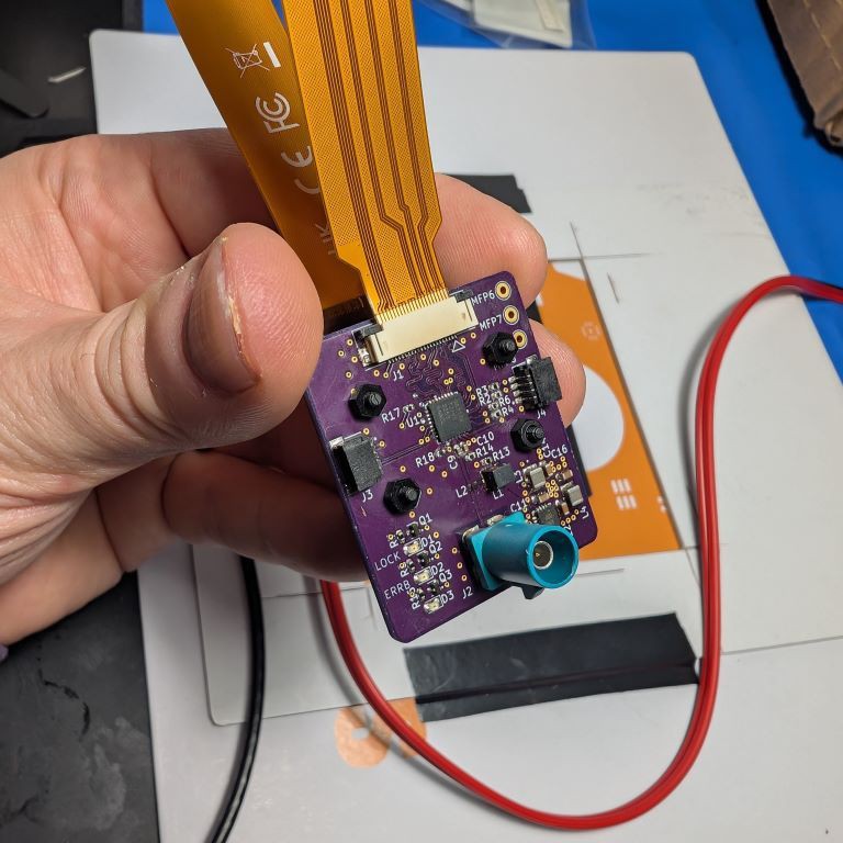
These were done on a 4-layer board from OSH Park and the controlled impedance guidance worked like a charm. I will detail layout in a follow up log but here is a picture of the working prototype before we dive into schematics.
![]()
Pretty decent soldering job on the first try, just needed to rework a few self-inflicted solder bridges. Great stencils from OSH Stencils.
On to the schematics.
The full schematics can be found on my GitHub repo.
The schematics may seem fairly simple because they are. These SerDes devices don't require much to get going outside of some basic connections. The majority of the work is in the layout which I'll detail in another log.
The EV kits for these parts also have full schematics but since they're EV kits, they have a lot more on the board than what's necessary so I optimized it down to be specific to this application.
The first page is the hierarchy of the design. This board is simple enough not to require a hierarchical design but I like to organize my schematics like a block diagram to allow for easier navigation. I can thank my first engineering manager for instilling hierarchical design best practices into me as a young engineer out of college.
Top level hierarchy of the design.
There are five sections of the design that are pretty consistent across all GMSL based designs.
- Connector - The connection to the outside world and to the deserializer.
- Power - Everything needs power, but you'll see a line from the connector because I'm using power over coax allowing me to transmit a few Watts of DC power on the same cable as the GMSL link further reducing wires.
- Peripherals - This is anything that you want to hook up on the bidirectional communication channel of the GMSL link. I put QWIIC connectors so folks can plug in whatever they want. But again, these are transmitted at a different frequency on the GMSL link reducing wires.
- Camera - That is simply the 22-pin connector for the IMX219 RPI camera but in reality, this is the input PHY that we are serializing on the link.
- GMSL - Best for last. This is the bulk of the schematic with the serializer. If you notice, the peripherals and camera both go into this sheet. This is because GMSL can combine both high speed and low speed data feeds on to the coax cable. Also, this is transmitted at microsecond latency.
Let's just into the fun one first, the main GMSL schematic.
![]()
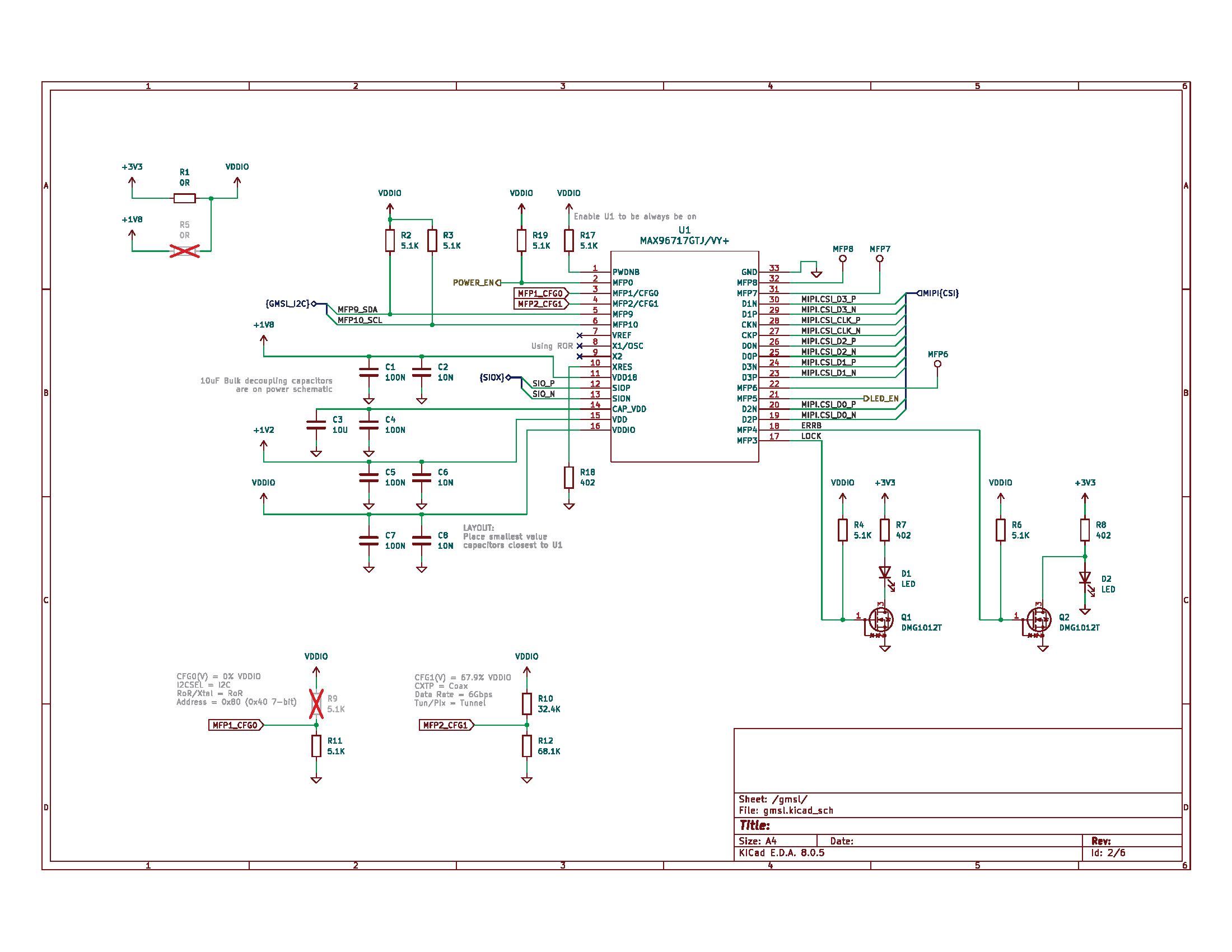
Not too much going on but let's start in the top right corner and work counter-clockwise. I recommend opening the schematic and following along. Note: minor fixes where made on the LED logic and power enable pin.
You'll see some testpoints labeled "MFPx", MFP stands for Multi-Function Pin and it's like a GPIO on steroids. Each MFP has... multiple functions that are specific to each device but they are mainly I2C, UART, GPIO, SPI, ADC, etc. capable pins that can be configured for whatever your application needs. You can also see MFP3 and MFP4 on the bottom right which are used to indicate that the GMSL link is locked and if there is an error on the device. Not mandatory to route these out but helpful for a quick visual indication of the link's health.
Next is the bulk of the layout and schematic planning, the MIPI-CSI2 interface. At first glance, it appears I completely messed up the pin connections however, these GMSL devices allow for lane remapping and polarity remapping. After talking to the layout engineer (yes, I talk to myself), these were the ideal connections to significantly simplify the MIPI routing. The only thing you can't remap is the clock lane but I could change the polarity which helped.
There are registers in the device that also need to be reprogrammed to remap these but I selfishly prioritize hardware simplicity over software complexity. The register programming is straightforward but doing changes like this require good coordination among the schematic engineer, layout engineer, and software engineer.
Onto the power supply, it is a simple combination of bulk and decoupling capacitors that is outlined in the datasheet. I made a note of the PCB placement to have the smallest values closest to the IC. The bulk capacitance is on the power page so I made a note of where they are.
You'll see one rail, CAP_VDD, which doesn't have a power feed but is needed to decouple the core VDD supply. The other rails are:
- VDDIO - (I chose 3.3V to support the QWIIC connectors but it can be any range from 1.8V to 3.3V). Always (please) have a discrete rail called VDDIO rather than using 1V8 or 3V3 for the GMSL logic. This is because VDDIO can change, which is fine, but if you miss something on the page that is pulled to this rail, you will have issues or burn up a part.
- VDD - which is the core supply and can be provided a voltage supply of 1-1.2V. I chose 1.2V since that is the typical camera voltage power supply and the PMIC chosen outputs that value.
- VDD18 - this is just the 1.8V device rail
Buried in these pins, you'll also see SIOP and SION. I'm not sure the exact acronym breakdown but I call these "Signal Input/Output Positive" and "Signal Input/Output Negative". GMSL supports both single-ended (coaxial) and differential (shielded twisted pair) configurations of the cable. These will be discussed on the connector page.
Next up is the XRES which is the 402 Ohm termination resistor for the PHY.
You'll also notice no-connects on the crystal oscillator inputs X1/X2. Typically, a clock source is needed to drive these parts but the newer MAX96717 has a feature called ROR allowing me to use the clock on the deserializer which is recovered from the GMSL link. This means fewer parts and easier layout, and no 25MHz radiating on my sensor board. If this camera has any GPS based devices near or connected to it, you'll know 25MHz likes to peek it head out right in the middle of the GPS band.
A few more MFPs on the part. MFP9 and MFP10 break out the main I2C channel that is then connected to the QWIIC connector. MFP0 is used for the power enable GPIO of the camera. PWDNB is the reset pin of this device, I have it pulled high to always have the device enabled but it could be controlled if desired.
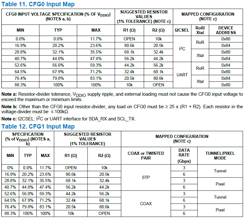
MFP1 and MFP2 have a unique usage as the configuration pins of the device and bootstrap the basic settings required for a GMSL link to be operational. I advise against using these unless it's a last resort because any noise on these pins could cause the part to boot in the incorrect manner. Lower in the page, you'll see the voltage divider and associated settings. I always try to be explicit in schematics with my bootstrap intentions. You'll see in the comments that coax, 6Gbps, I2C, RoR, tunnel and the I2C address of the device.
Here are the CFG values and what they configure.
![]()
The CFG0 and CFG1 configuration capabilities.
Lastly, you'll notice some interesting resistor values of 5.1kOhm and 402R used for multiple purposes. This was done intentionally to minimize the different BOM components. When I was a design engineer, different BOM values translated to more line items to manage, source, and worry about. 5.1kOhm as a pullup is more than sufficient for I2C or the FET gates. It is a required component value for the power over coax filter so I back propagated the value through the schematic. And coincidentally, 402R is actually a good enough value for the LEDs but a mandatory value for the GMSL device. So they're not random but meant to help simplify the design needs. You'll see these two values again on the power page.
A lot of detail on this page so I'll detail the other four pages in the next log!
-
Component Selection to the Project
11/18/2024 at 01:17 • 0 commentsI had some internal training I needed to prep for but back to this project.
When choosing chips for a link, the unique thing is that you have to choose both a serializer and a deserializer for the link. When it comes to GMSL, there are a few flavors of each but I'll spare you the sales pitch. I definitely wanted one camera but thought about the expansion to a second camera. ADI offers a single, dual, and quad deserializer so I chose the dual to allow for the second camera link. Therefore, the serdes pair chose was the MAX96717 and MAX96716A. Feel free to reach out if you have questions on the other chips.
![MAX96717 Pin Configuration MAX96717 Pin Configuration]()
MAX96717 Pin Configuration ![MAX96716A Pin Configuration MAX96716A Pin Configuration]()
MAX96716A Pin Configuration These chips were chosen because they offer some new features like Reference clock Over Reverse channel (RoR), Tunnel mode, and Forward Error Correction (FEC). All of which simplify and robustify the serial link. There's other nice features we'll discuss later in the project.
With these two, we'll be leveraging the reverse channel which allows us to talk I2C over the cable while simultaneously transmitting high bandwidth video data on the forward channel and low latency (microsecond) communication on the reverse channel. This is an asymmetric, full duplex communication protocol meaning there is a lot of bandwidth available in one direction and typically a little bit of bandwidth in the other direction but both directions can communicate at the same time.
Additionally, I'll be leveraging the power over coax (PoC) capability of GMSL and using a Power Management IC (PMIC) on the camera to create a bunch of voltages needed on the remote camera from a single voltage. In the GMSL Hardware Design Guide, we detail how this is chosen and I'll address it in more detail in a later log.
But the PMIC chosen is the MAX20049 from the Automotive Power group at ADI. The nice thing about this PMIC is that it has a lot of orderable part numbers with different configurations so it's preprogrammed to boot up with certain power rails. This is helpful because most cameras need similar rail voltages. For this project, I chose the MAX20049ATED variant. The voltages are 3.3V for GMSL and QWIIC, 2.8V for camera sensors, 1.8V for GMSL and camera sensors, and 1.2V for GMSL and camera sensors.
![MAX20049 Simplified Block Diagram MAX20049 Simplified Block Diagram]()
MAX20049 Simplified Block Diagram So with the serializer, deserializer, and camera PMIC chosen, it's onto starting the schematics!
-
SerDes Basics Applied to GMSL
10/09/2024 at 14:14 • 0 commentsBefore we get too deep into the technicals of the project, I wanted to take a moment to explain why I'm even doing this. Obvious question, why not just bundle up a Raspberry Pi and stream it?
SerDes is a portmanteau of the words SERializer and DESerializer so when we talk about serdes, it's referring to the whole link. A modem is another portmanteau of MODulater and DEModulator which takes digital signals and makes them analog. What both of these technologies do though is convert data from one format to another format to easier handling, the data remains the same but it's just structured in a more convenient format.
SerDes devices serialize and deserialize a data stream with the most obvious and primary benefit of reducing wires. This was the main driver of needing GMSL because the automotive industry wanted cameras and displays throughout the car. The issues quickly became cabling and EMC.
Let's use an example of a parallel 10-bit camera: each bit is a signal, plus the timing signals (HS, VS, and DE), plus low speed communication to program a camera (let's assume I2C), and power. That's over 15 wires to get a fairly low resolution camera. Each signal is a wire that can fail. All are moving at a decent clock frequency requiring the bits to be very synchronized but also creating radiated emissions. On top of that, there are the IR losses of the wire that degrade the signal limiting the reach.
Additionally, in automotive and any robotics applications cabling translates to weight
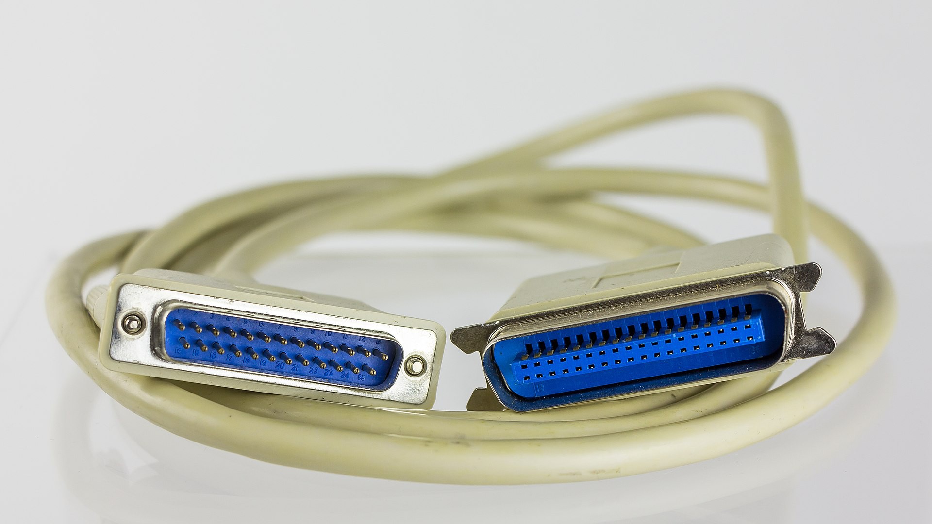
Another example a lot of us are familiar with is the infamous printer cable:
![]()
It was big, bulky, and carried a lot of wires. However, when you do a quick Google search of "printer cable" all that comes up are USB cables. USB standing for Universal SERIAL Bus, so you may not realize it but you've been using a form of serdes already in your day to day!
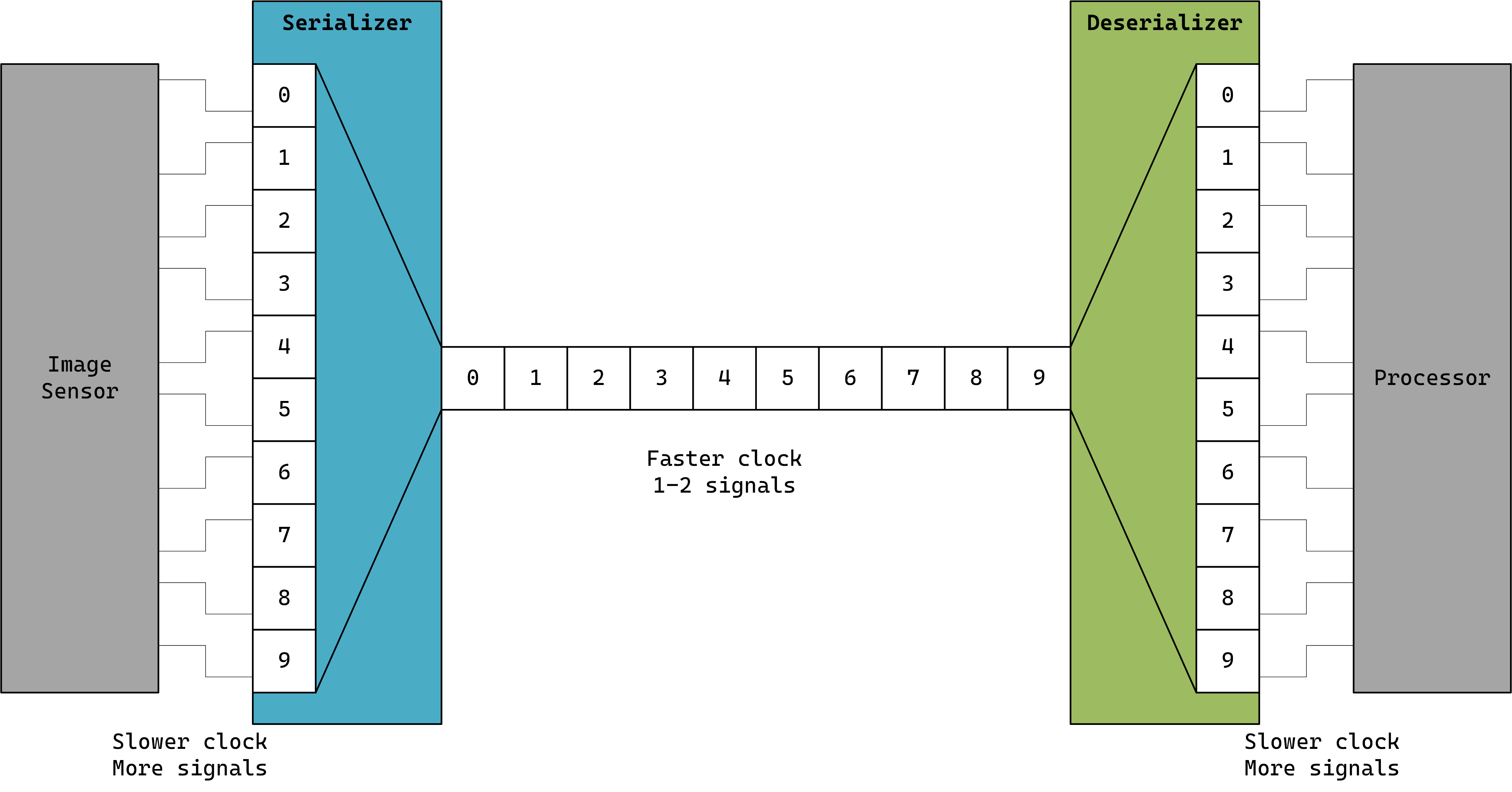
So how is the data sent in a serial format? Well, data is data and engineers get creative solving problems. Serdes from a very high level puts the data into packets versus discrete parallel signals and the packet of data is clocked in and out faster to reduce the number of wires if the system can accommodate generating a faster clock.
There is numerous resources describing how serdes works so I won't go deep into the details (unless you wanted my take) but essentially below is a simplified block diagram of the serdes operation. The serializer clocks in all the parallel signals then packetizes the data and clocks out the data at a much faster rate. By the time the packet is sent out, the serializer is ready to packetize the next set of data. The deserializer's role is to take that data and depacketize the stream into the output interface format.
![]()
This all happens so fast that it shouldn't even seem like there is something else happening between the sensor and processor.
This is great but why go through the trouble of using serdes in the first place.
By using serdes devices, we can now extend where we put the camera and with GMSL, simplify the overall system architecture. This is because the GMSL serdes not only transmits the high bandwidth data, but it can also packetize GPIOs, I2C, SPI, UART, etc on the single cable. Additionally with coax cable applications, we can send power over the coax with a simple inductor network. GMSL is also automotive certified and will adapt to extreme temperatures.
Going back to the original design problem with a GMSL link, I can put the camera, I2C communication (I'll be using QWIIC connectors) and power all over a single wire out to a camera that is remote in my backyard. And given that it gets cold where I'm at, the cable will be able to adapt to the changing temperature conditions without degrading the signal.
I'll be getting into the different aspects of these features as we go through the design, but let's take a look at the serdes pair I'll be using.
-
First Log: What is GMSL?
10/04/2024 at 12:43 • 0 commentsGMSL stands for Gigabit Multimedia Serial Link and it is a SerDes (serializer-deserializer) technology created by then Maxim Integrated, now Analog Devices. It was designed for the automotive industry to help transport video and sensor data over long distances in a car but also managing to handle harsh environments like automotive EMC and temperatures.
It's by no means a new technology and have been in production for over 20 years going on it's third generation of devices.
The primary benefit is to reduce cabling and handle large bandwidths of uncompressed data. So on one single coax cable, you can transmit 6Gbps of data, low speed communication (I2C, UART, SPI), and power. Typical distances are around 15m but they could go further.
Historically, GMSL has been limited to the automotive industry with the details keep behind an NDA but now Analog Devices (ADI) has decided to open up this technology publicly with the GMSL2 generation of devices. I've been using a variety of SerDes devices for 10+ years but have been directly supporting GMSL for almost 7. Personally this was really exciting to me because I'm a maker at heart and have always wanted to share this technology with the maker community because I think it could really help enable a lot of cool projects.
In this project, I wanted to make an underwater fish camera and beehive monitoring camera for my wife to watch the fish and bees during the winter. GMSL technology is rated from -40C to 105C (automotive) and has a variety of features that would allow adding remote sensors without the need of additional cables.
The first part of this project will be designing the camera and walking though all the various design ideologies for consideration of using GMSL. I'm doing this project as Tom the hobbyist so all views and opinions are my own but hopefully it could help you make some cool edge camera designs. All the documentation is publicly available without NDA along with the software.
Minimax Camera
Using GMSL to power, control, and receive a Raspberry Pi camera over distance.
 tom
tom