Thomas Flummer
-
Controlling the LEDs from Micropython on the Supercon.8 Badge
11/01/2024 at 21:14 • 0 commentsSimple micropython python snippet to control the LEDs on the Blinky Loop SAO
The neopixel library seems to be already on the micropython image on the badge, to no need to add a library.
This does a simple rainbow that rotates continuously. It's a little jumpy so there is room for improvement, but the code should be relatively simple to read.
from machine import Pin import neopixel import time # setup Blinkyloop LEDs (pin 22 is GPIO1 on SAO port 4) np = neopixel.NeoPixel(machine.Pin(22), 12) def rainbow(np, brightness): n = np.n color_map = (255, 170, 128, 85, 0, 0, 0, 0, 0, 85, 128, 170) while True: for j in range(n): for i in range(n): r = color_map[i] g = color_map[((i + 4) % n)] b = color_map[((i + 8) % n)] np[((i + j) % n)] = (round(r * brightness), round(g * brightness), round(b * brightness)) np.write() time.sleep_ms(50) rainbow(np, 0.1) -
Testing the components
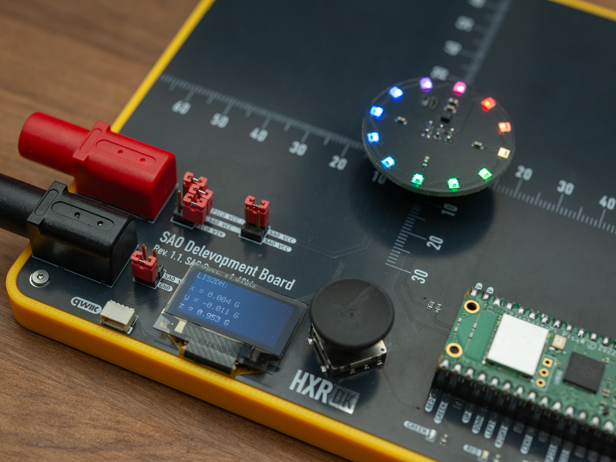
10/27/2024 at 14:27 • 0 commentsI have made a test planform based on the Raspberry Pi Pico module, and for this I will be using the Pico W variant. It doesn't really matter for the test, but it will match the one used on the Supercon 8 badge, though this test platform currently runs Circuit Python, and the code snippets below if based on that.
![]()
The test first runs a little rainbow animation to check that all the LEDs are connected properly, and has survived the soldering, sanding and cleaning.
import board
import busio
import time
from rainbowio import colorwheel
import neopixel

pixel_pin = board.GP26
num_pixels = 12

pixels = neopixel.NeoPixel(pixel_pin, num_pixels, brightness=0.1, auto_write=False)

def rainbow_cycle(wait):
    for j in range(255):
        for i in range(num_pixels):
            rc_index = (i * 256 // num_pixels) + j
            pixels[i] = colorwheel(rc_index & 255)
        pixels.show()
        time.sleep(wait)

for n in range(2):
    rainbow_cycle(0)
After that, the LIS2DH accelerometer is tested. Electronut labs has a library for that. I simply connect to the accelerometer, configure it to use the 2G range (regular gravity falls nicely within that), and then show the X, Y, and Z values on the screen.
import board
import busio
import displayio
import adafruit_displayio_ssd1306
import time
from adafruit_display_text import label

import terminalio

import electronutlabs_lis2dh12

# release, otherwise we won't be able to attach to GP15/14, as the display uses them
displayio.release_displays()

# initialize DEV board I2C
i2c_dev = busio.I2C(board.GP15, board.GP14)

# initialize SAO I2C
i2c_sao = busio.I2C(board.GP5, board.GP4)

display_bus = displayio.I2CDisplay(i2c_dev, device_address=0x3c)
display = adafruit_displayio_ssd1306.SSD1306(display_bus, width=128, height=64)

# Make the display context
splash = displayio.Group()
display.root_group = splash

# Draw a label
text = "LIS2DH:"
text_area = label.Label(terminalio.FONT, text=text, color=0xFFFF00, x=0, y=5)
splash.append(text_area)

lis2dh12 = electronutlabs_lis2dh12.LIS2DH12_I2C(i2c_sao, address=0x19)

lis2dh12.range = electronutlabs_lis2dh12.RANGE_2_G

# create the label
x_label = label.Label(
    font=terminalio.FONT, text="x = {} G".format(0), scale=1
)

y_label = label.Label(
    font=terminalio.FONT, text="y = {} G".format(0), scale=1
)

z_label = label.Label(
    font=terminalio.FONT, text="z = {} G".format(0), scale=1
)

# set label position on the display
x_label.anchor_point = (0, 0)
x_label.anchored_position = (0, 20)

y_label.anchor_point = (0, 0)
y_label.anchored_position = (0, 35)

z_label.anchor_point = (0, 0)
z_label.anchored_position = (0, 50)

# add label to group that is showing on display
splash.append(x_label)
splash.append(y_label)
splash.append(z_label)

while True:
    # Read accelerometer values (in m / s ^ 2).  Returns a 3-tuple of x, y,
    # z axis values.  Divide them by 9.806 to convert to Gs.
    x, y, z = [value / electronutlabs_lis2dh12.STANDARD_GRAVITY for value in lis2dh12.acceleration]

    x_label.text = "x = %0.3f G" % (x)
    y_label.text = "y = %0.3f G" % (y)
    z_label.text = "z = %0.3f G" % (z)

    # Small delay to keep things responsive but give time for interrupt processing.
    time.sleep(0.1)
I ended up simple switching out the SAO and resetting the Pico, to run the test for the next on. Tilting the test board will result in different values, and checking that they fall at about 1G pointing down when steady. All the roughly 35 SAOs prepared all worked without any errors. The accelerometer footprint is a little fiddly, but good solder paste application helps in a proper manufacturing.
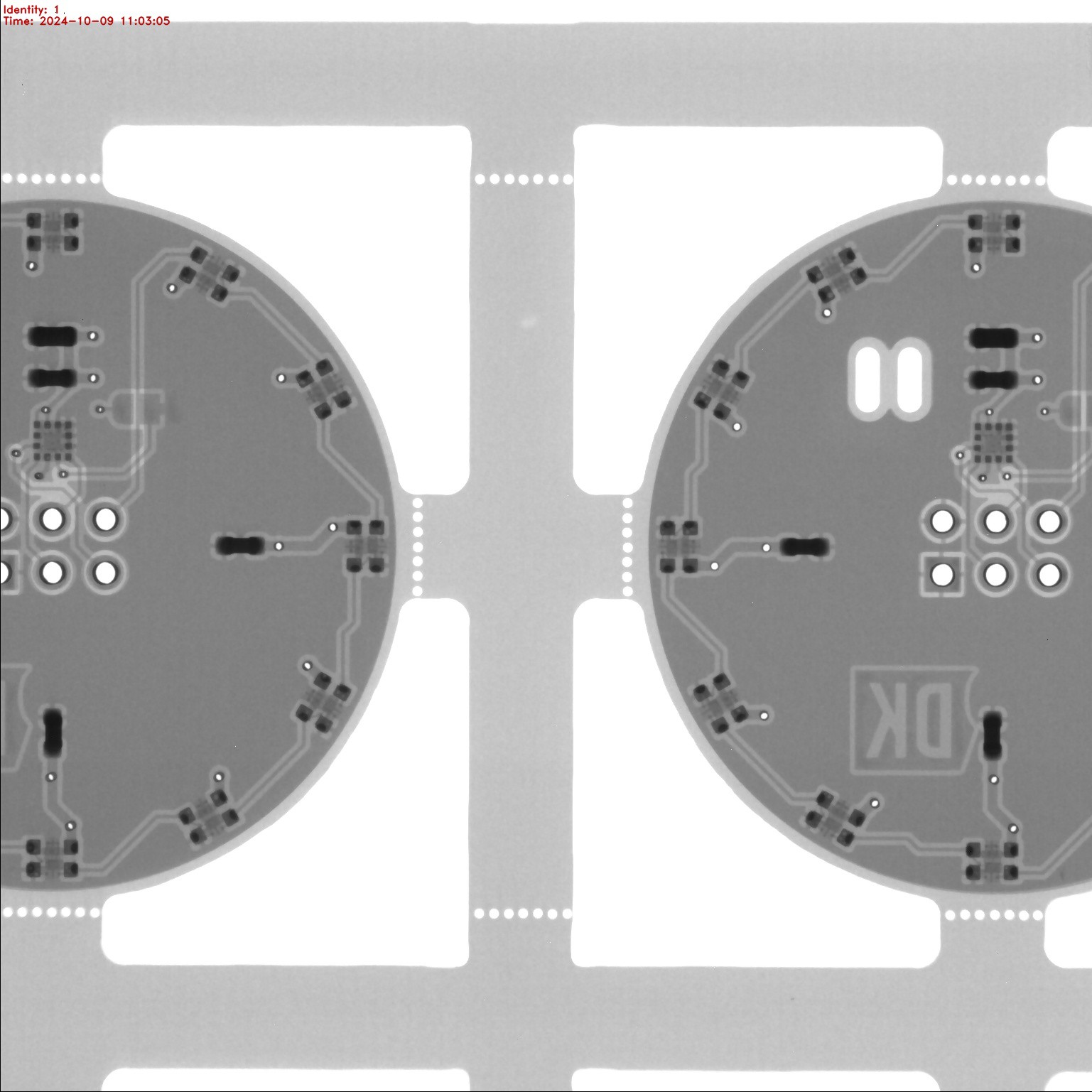
This type of WS2812 is a bit tricky, as it's recommended to bake the parts first before assembly, to help eliminate any of them breaking when they go through the reflow soldering. As that belongs to the "Standard" and not the budget PCBA service, I also ended up getting X-rays from when they checked the soldering:
![]()
-
Assembly and Cleaning
10/27/2024 at 14:02 • 0 commentsI had these boards populated with all the SMD parts and for this, the board was panelized in a 2x2 configuration, with a frame and "mouse bites" (row of small holes in the PCB), to allow separation.
I positioned the mouse bites outside the edge cut circle, so that they could be sanded away after separation.
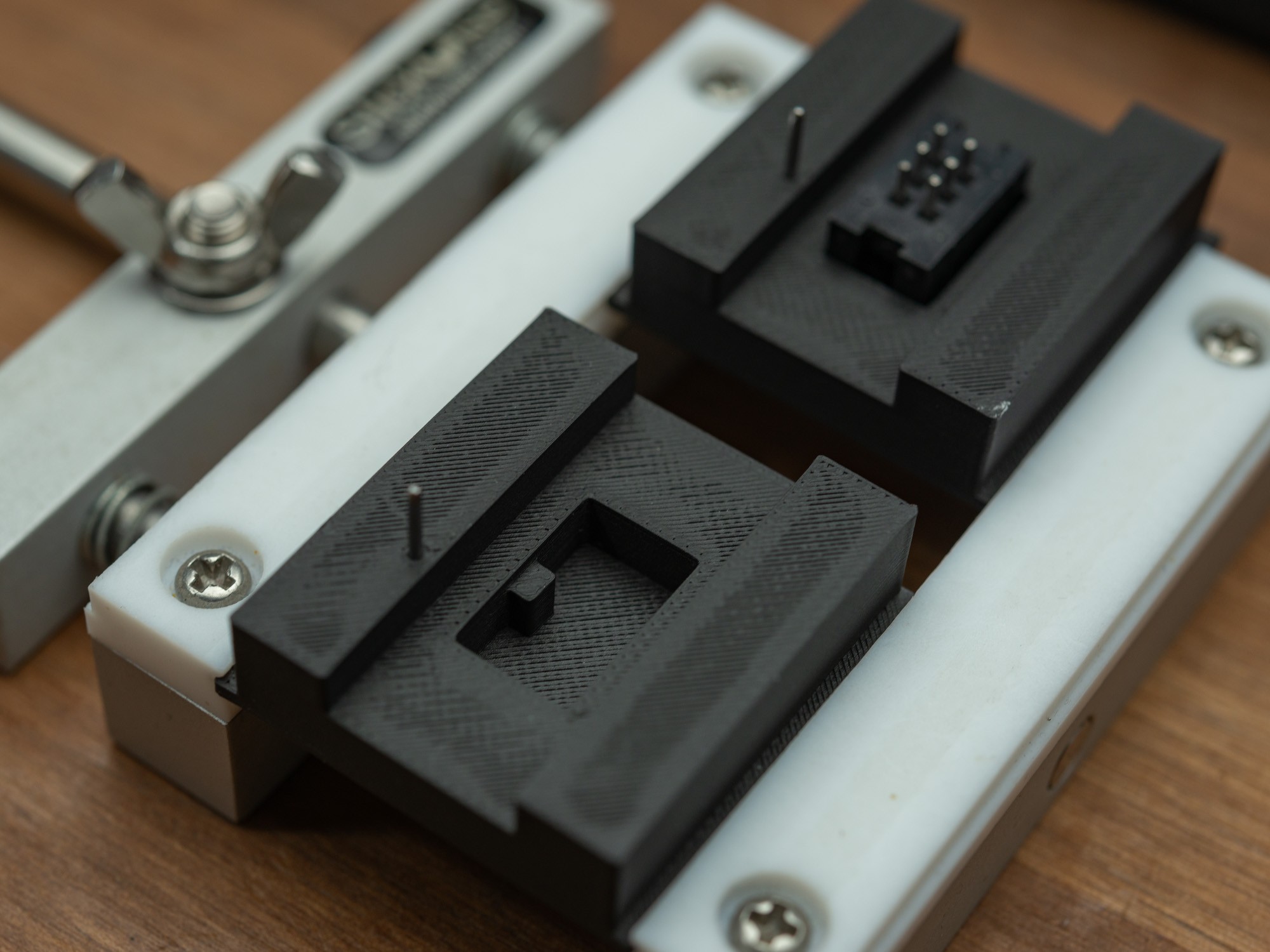
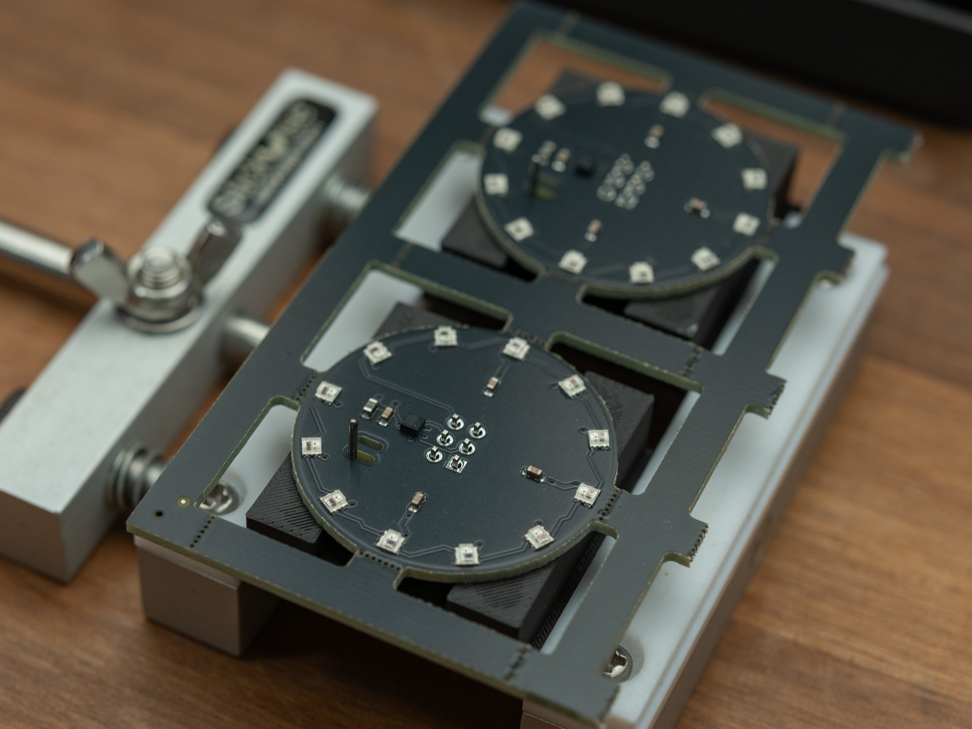
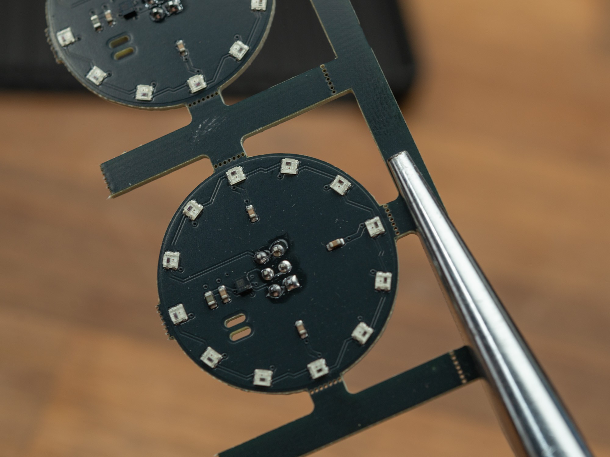
So ease the soldering of the SAO connector, I decided to first half the panels and then using a 3D printed jig, solder in the connectors, before the full separation and sanding.
![]()
The 3D printed jig with small steel dowels that is used to align the board using one of the cutouts for the SAO leash in the PCB.
The notch in the bottom makes sure the SAO connector is oriented correctly.
![]()
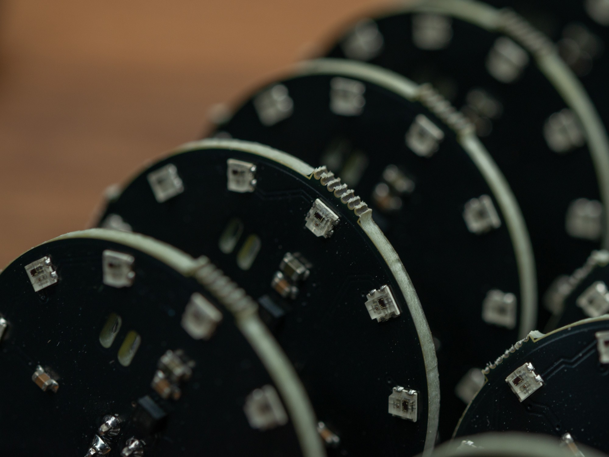
After soldering the connectors, it was time for depanelization.
![]()
They snap relatively easy, but holding the thin rails with a needle nose plier helps a lot with a relatively clean break and protects you fingers when doing many.
![]()
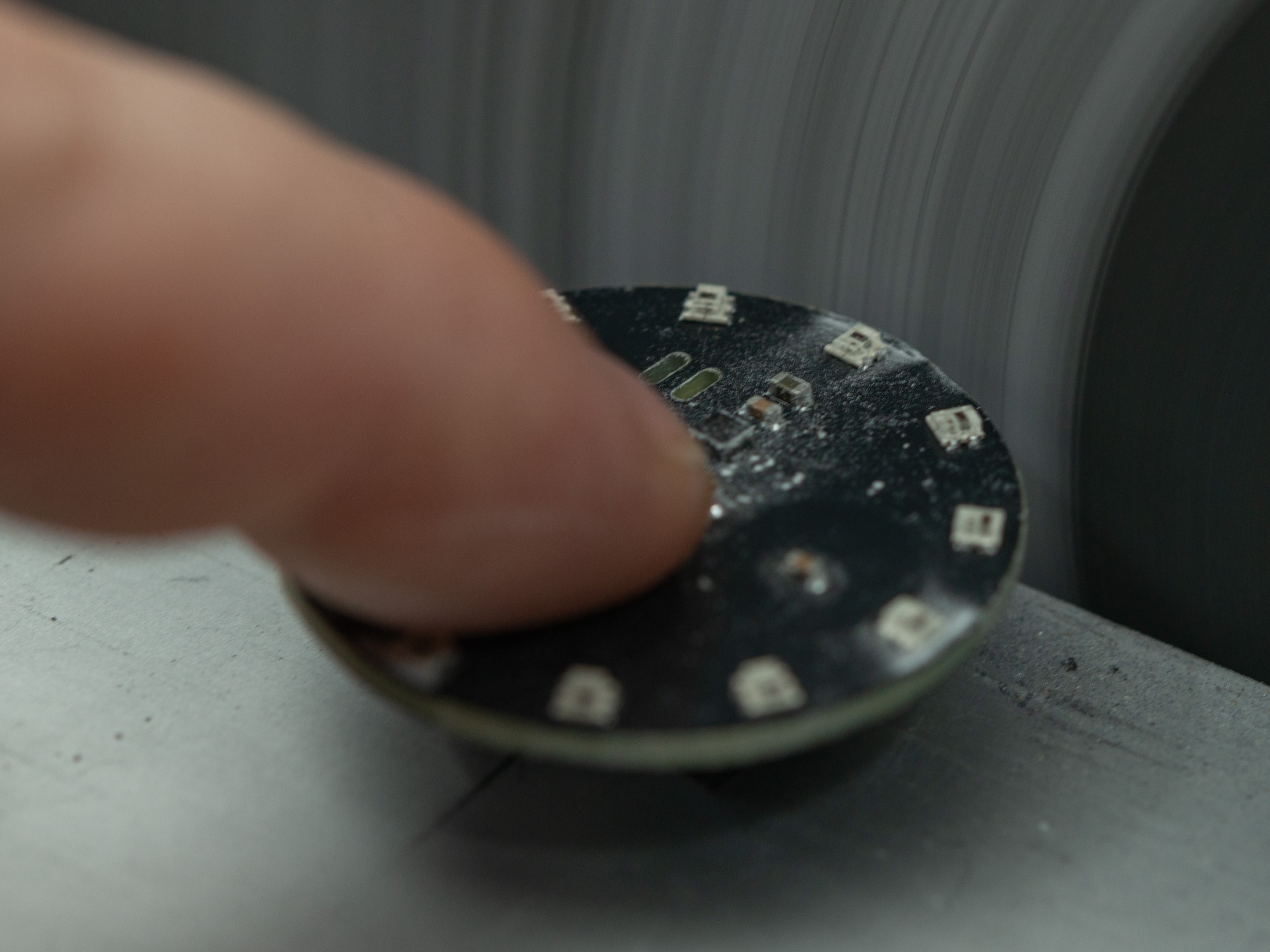
The excess PCB that was sticking out was sanded away with a disk sander. It's a bit fiddly and messy so not an ideal way, but there isn't that many options when you want a fairly clean outer edge on a circular PCB and want machines to assemble the small parts.
![]()
It's not always perfect but should be good enough to not hang on to peoples clothes and maybe get ripped off.
![]()
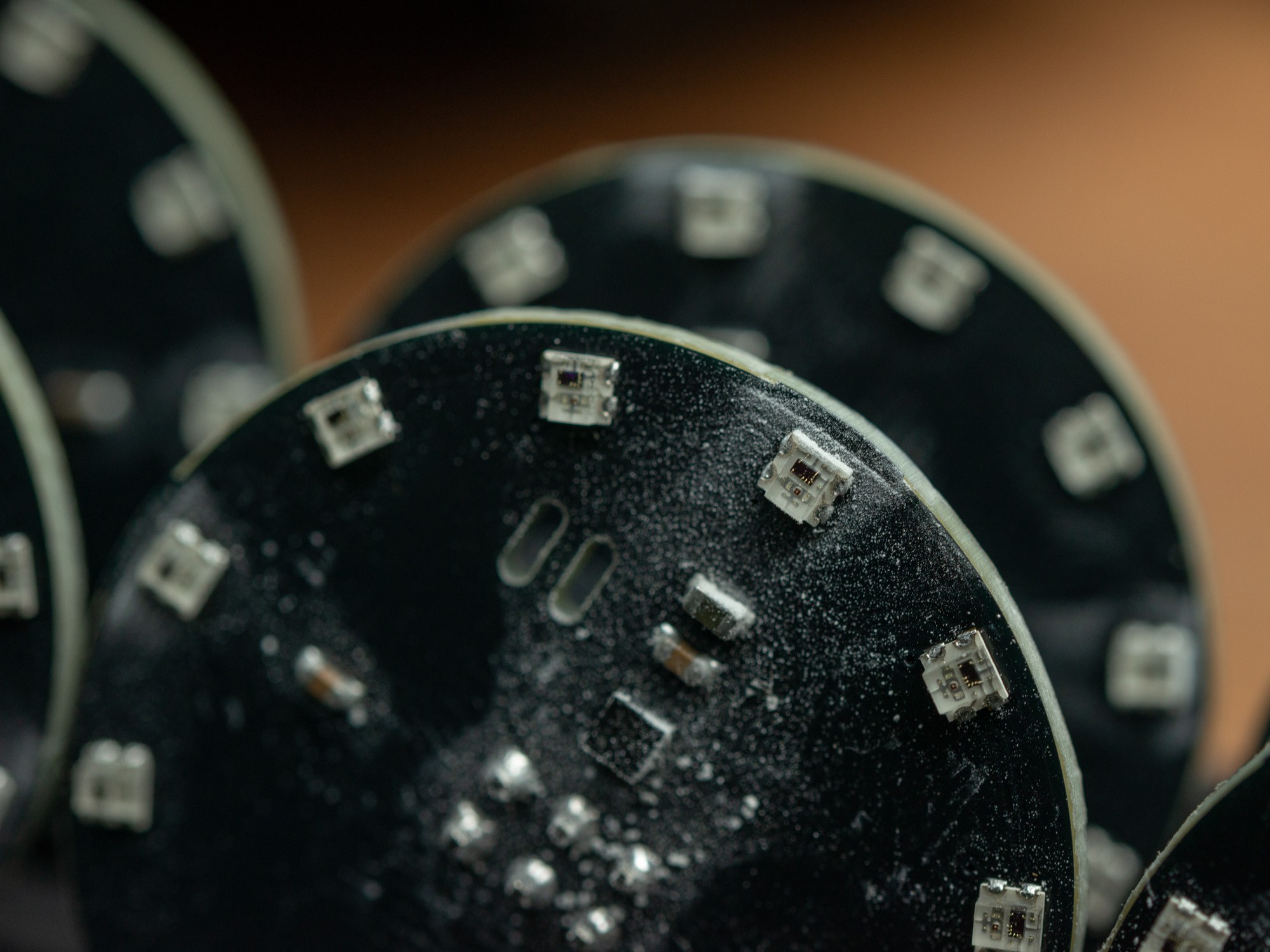
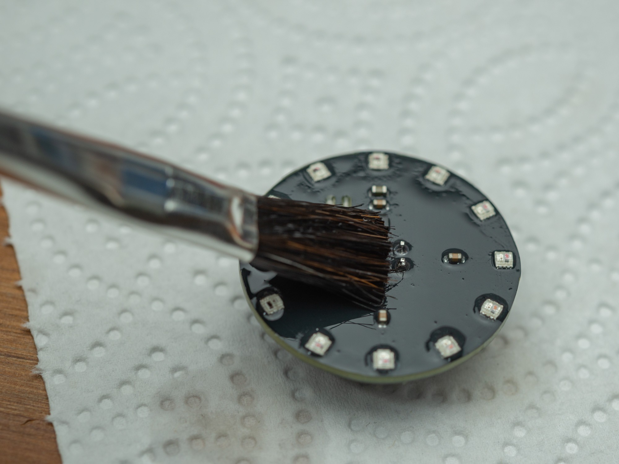
They end up pretty messy, after being sanded in 4 spots, so to get rid of that and the flux from the soldering, I decided to give them a wash in isopropyl alcohol (IPA), and dry them with paper towel.
![]()
Looks better after cleaning.
![]()