 Yann Guidon / YGDES
The ternary mark from PEAC gets mixed with the combined parities and the last log 23. SU(3) shows that the previous approach didn't work. A little different analysis shows that a pair of half adders can do the trick, reversibly : a simple mod3 addition.
- the marker is encoded as 00, 01, 10
- the combined parities should be encoded similarly for consistency and symmetry, so a OR is replaced by a XOR.
Let's just look at the corresponding table:
+   0  1  2
   ---------
0 : 0  1  2
1 : 1  2  0
2 : 2  0  1
In binary :
+   00  01  10
   ------------
0 : 00  01  10
1 : 01  10  00
2 : 10  00  01
It is easily decomposed into LSB:
 +   0  1  0
    ---------
00 : 0  1  0
01 : 1  0  0
10 : 0  0  1
and MSB:
+   0  0  1
    ---------
00 : 0  0  1
01 : 0  1  0
10 : 1  0  0
That's pretty low density, but not surprisingly. So the equations are pretty easy to generate.
S0 = (A0 ^ B0) | (A1 & B1)
S1 = (A0 & B0) | (A1 ^ B1)
So it looks like two interwoven half-adders with a pair of OR.
What about the subtraction ?
x + 0 mod3 = x
x + 1 mod3 = x-2
x + 2 mod3 = x-1
so subtraction is achieved by a "swap" of MSB and LSB at the receiver end.
.
I thought the circuit would be deeper and more complex, so it's a good surprise. Check it there.
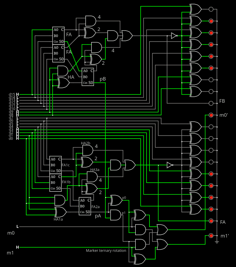
That's a total of 9 half adders, 6 full adders, 4 ORs and a few more gates.
Time to test the VHDL again.
Aaaaand it's a dud again, as the adder outputs 11. I had forgotten how to properly make a Karnaugh map...
Discussions
Become a Hackaday.io Member
Create an account to leave a comment. Already have an account? Log In.