 Yann Guidon / YGDES
The stats collected in log 70. Stats with GrayPar17 and PEAC16x2 paint a strange picture...
Initially I used XOR to combine the marker with the 3 parities and it wasn't great because they would cancel each other.
Then ADD3 is a mixed bag: some bits are OK (S0), bad (S1) or great (S2).
Naturally the idea is to reproduce the circuit of S2 and apply it to S0 and S1. What could go wrong this time ?
- S0 depends on only 2 inputs and it's "meh".
- S1 depends on 4 and it's bad, and I have no idea why.
- S2 is "great" and depends on 6 inputs.
So I'm going back to the ADD3 and copy-paste the circuit of S2. And to be honest I have no idea what I'm doing or how to make it work but it looks "interesting".
Let's try...
The table is puzzling
     000  001  010  011  100  101  110  111
000  000  001  010  111  100  111  111  000
001  001  010  111  100  111  110  000  001
010  010  111  100  101  111  000  001  010
011  111  100  101  110  000  001  010  011
100  100  111  111  000  001  010  011  100
101  111  110  000  001  010  011  100  101
110  111  000  001  010  011  100  101  110
111  000  001  010  011  100  101  110  111
From the distance it looks like an addition table. Since it's the same boolean equation that is used and applied cyclically, there is the same total number of set bits per column (4 ones and 4 zeroes for positions 0, 1 and 2). The diagonals, and other features are typical but...
- 111 should appear only 8 times and I see 13 occurrences on 3 diagonals.
- there are some 110 and 101 that break a diagonal of 111.
- The lower-right triangle looks normal for addition but the other half is weird!
So the operation is not reversible and it can't be reused as is. But the idea is interesting !
------------------------------------------------------------------
What else can be done to change the behaviour and the stats ? I haven't found any other reversible transformation and there might not be any...
The best I can do so far is tweak the stats by adding a parity bit to the marker, like in the first iteration, which mean we're back to using a full-size ADD3. The sensitive question then is which signal is assigned to the MSB, which is normally 0.
- To keep things simple and fast, m0×m1 would be assigned to S2 position, such that the XOR is performed during the add in the encoder.
- But S2 is the strongest position and the XOR could also be assigned to the weakest S1 position, moving the m0×m1 earlier (fortunately in parallel with the other Gray gates).
That means: at least 2 configurations to try and compare, derived from the earlier ADD3:
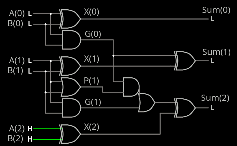
It's just a XOR on S2 but as mentioned before : S2 is the strongest bit so it makes no sense to mess with it.
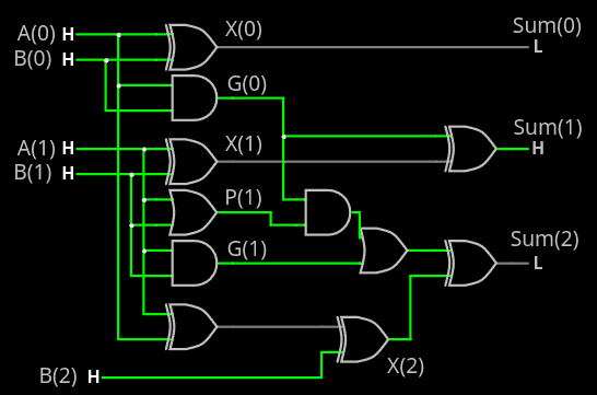
A(0) xor B(0) is reported to S(1), which can be pushed/moved in a way that avoids adding more latency.
Should be tested, out of curiosity.
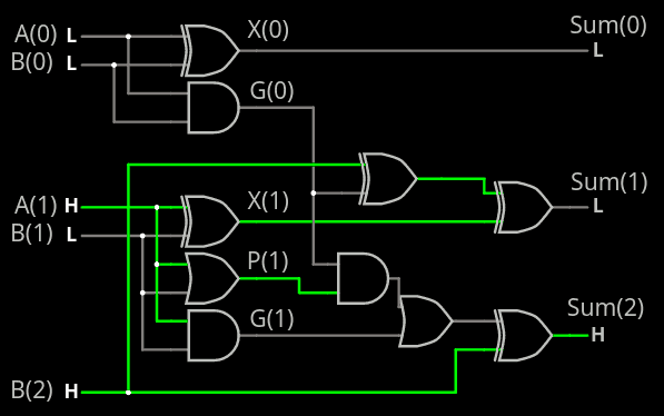
This time, the XOR is with B(2) since S(1) only depends on A and B, so maybe making it sensitive to other signals could help.
.
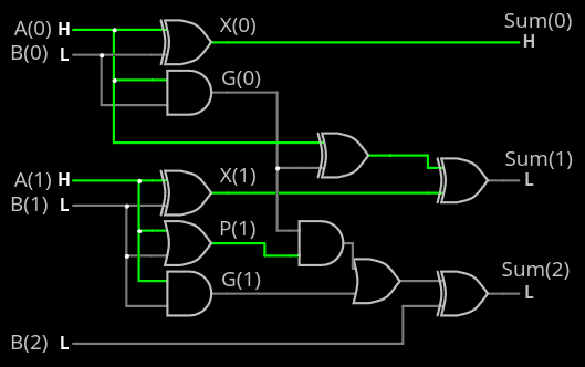
And of course it doesn't work because of a stupid confusion between P(0) and G(0). The schematics above are broken.
.
More stats need also to be collected for the "plain XOR" version (instead of ADD3) as well as the other flip lengths (2, 3 and 4)
Discussions
Become a Hackaday.io Member
Create an account to leave a comment. Already have an account? Log In.