Close
0%
0%

Skull of Fate SAO

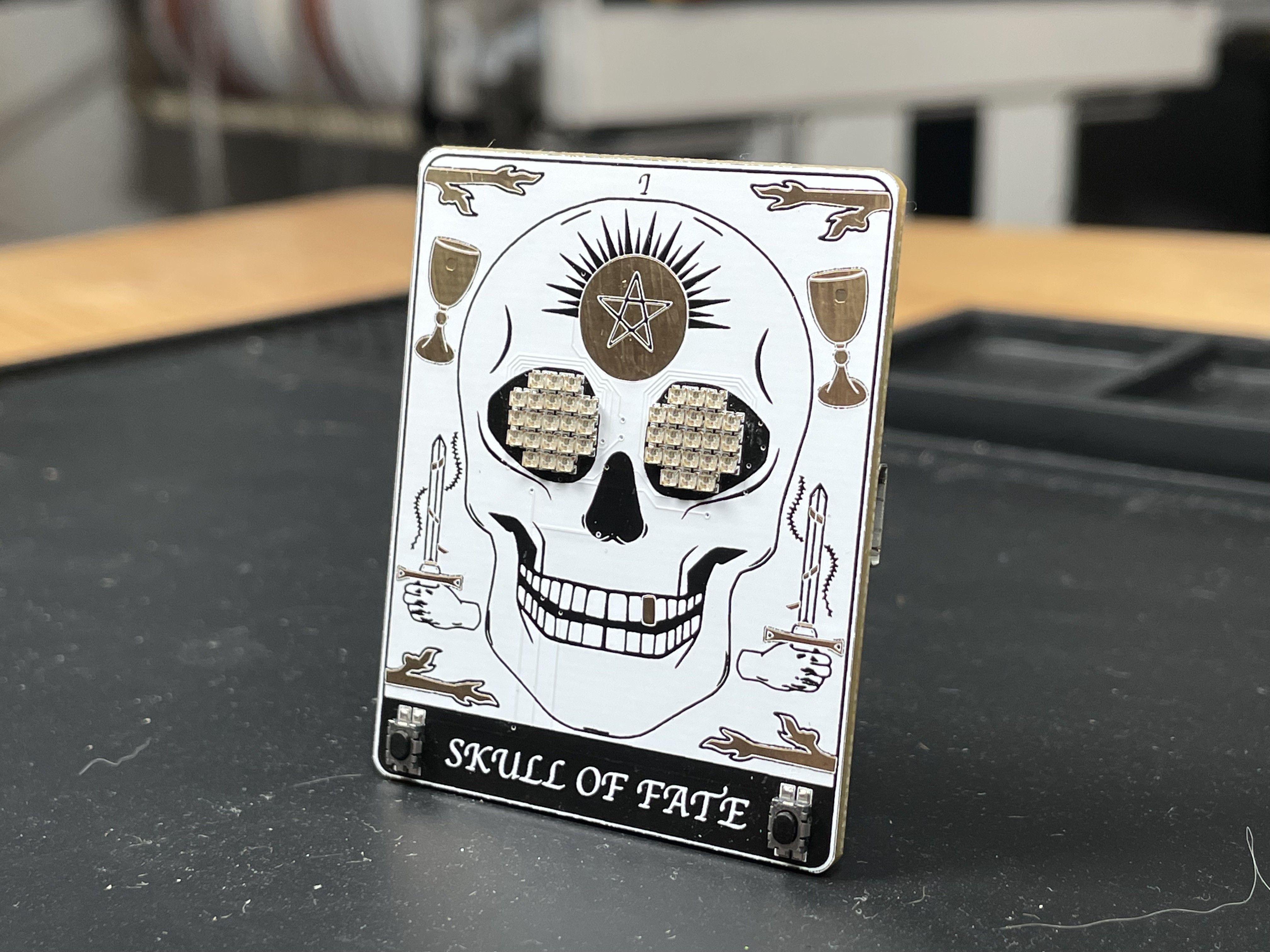
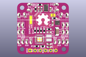
The Skull of Fate SAO is an interactive tarot RFID card featuring i2c host and i2c client capabilities and GPIO interface with the badge.

Similar projects worth following
Starting from
$45.00
makeithackin has 1102 orders / 6reviews
Ships from United States of America
Design and Features
The Skull of Fate SAO is a modern take on a tarot card inspired by ancient Greek mythology. The Moirai —also known as the Fates—were the personifications of destiny. They were three sisters: Clotho (the spinner), Lachesis (the allotter), and Atropos (the inevitable, a metaphor for death). The Skull of Fate represents Atropos, providing you with a unique tarot reading about the future. Each reading is an interpretation of the cards and their meaning from the original 78 card Rider Waite Tarot deck.

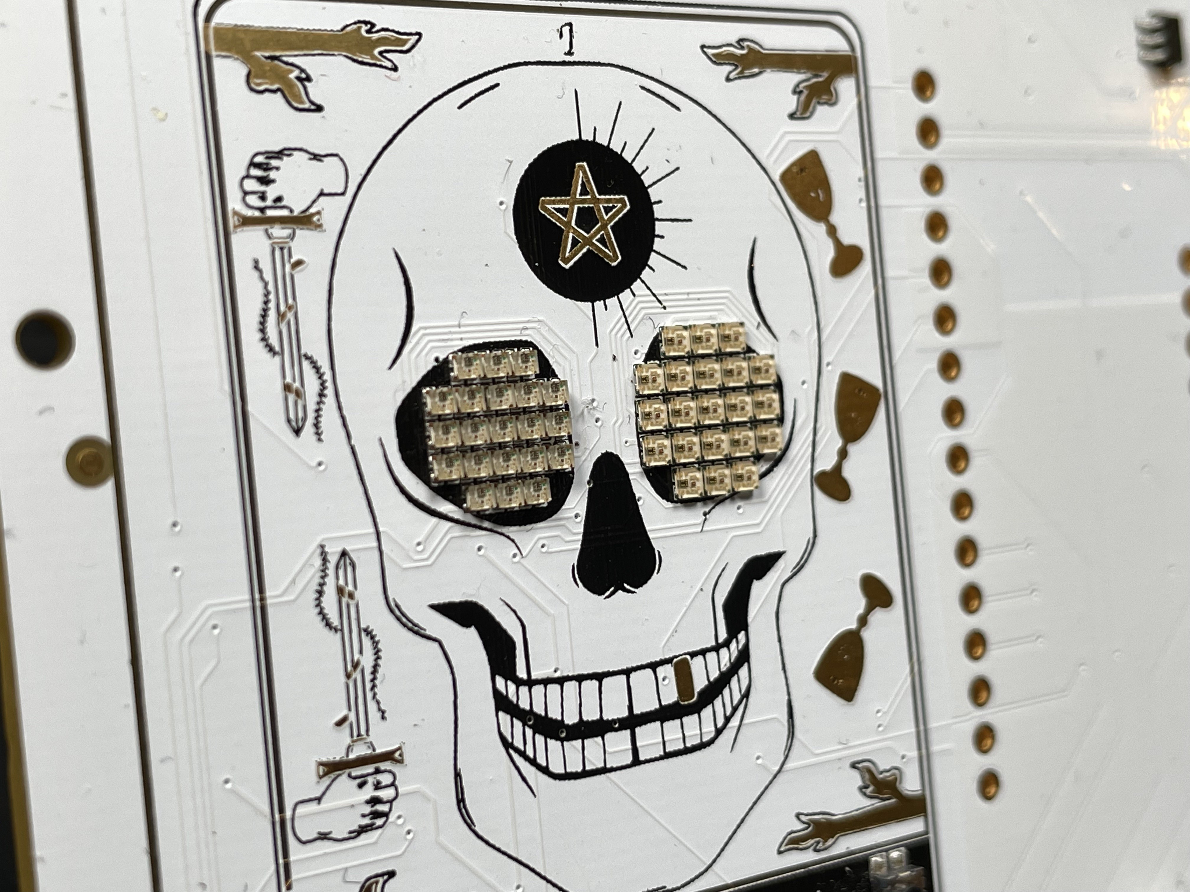
The card features original artwork, tarot readings, and LED animations. The skull has two modes, the default mode after turning on allows you to cycle through eye animations with the left button, and optionally change the color of the LEDs with the right button. Some LED eye modes are special, and change based on the accelerometer or microphone input, to be position and sound reactive.

Skull of Fate SAO Designed in collaboration between p1x317h13f and MakeItHackin 

Modes of Operation:

  • Default Mode: After turning on, you can cycle through eye animations with the left button and optionally change the color of the LEDs with the right button.
    • Some LED eye modes are special and change based on the accelerometer or microphone input, making them reactive to position and sound.
  • Tarot Card Mode: Holding down both buttons at the same time puts the device in tarot card mode, where a card is "drawn" at random from the deck and can be read by a phone or other NFC devices.
    • The NFC antenna is located at the upper part of the card.
    • Simply hold the reading device above the card any time after pressing both buttons to receive your reading.

Components and Materials

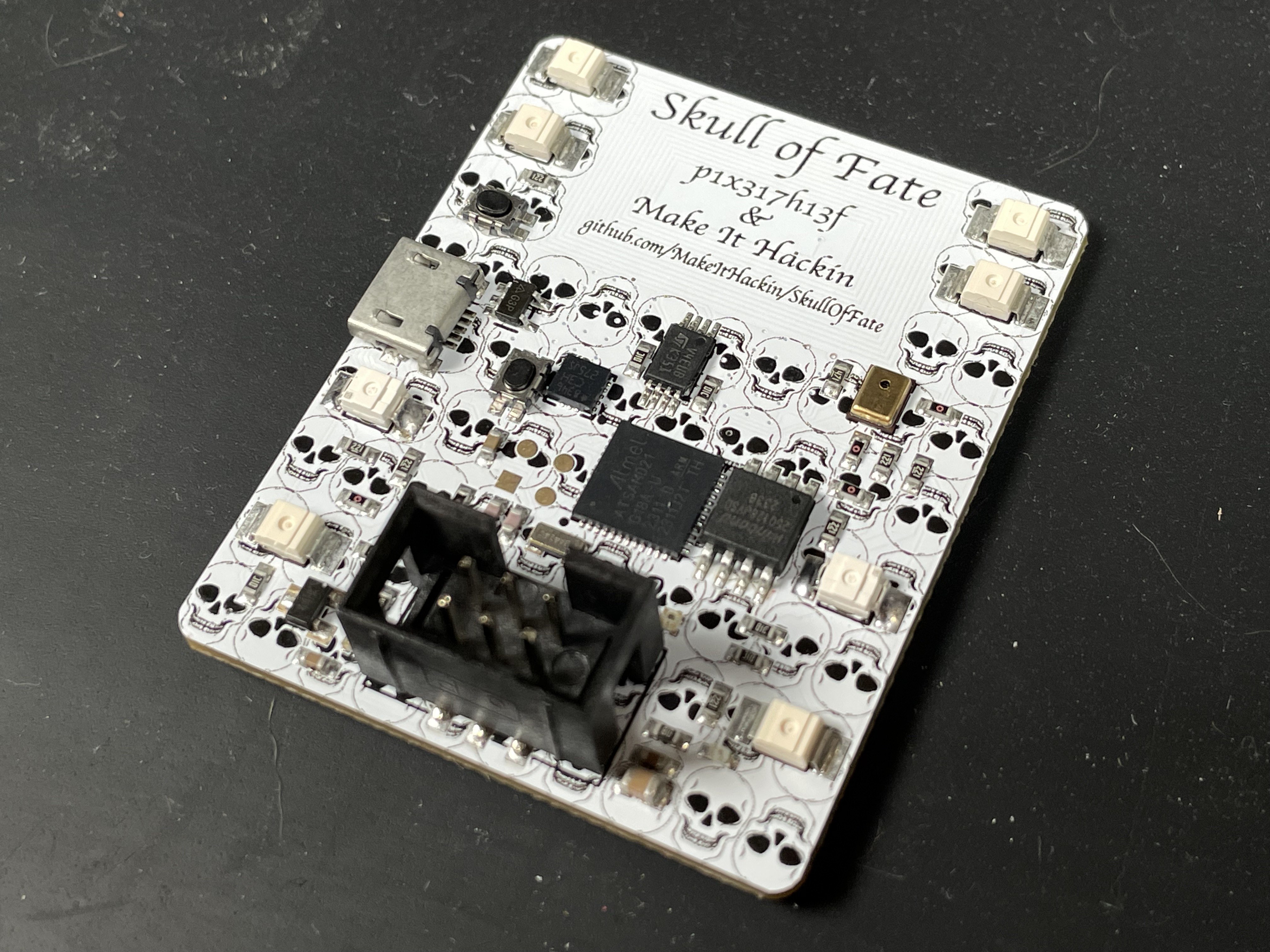
  • Microcontroller: SAMD21 (Arduino compatible)
  • Accelerometer: Adafruit LIS3DH
  • NFC/RFID Chip: ST25DV64KC (Adafruit breakout)
  • PDM Microphone
  • Magnetic Hall Effect Sensor
  • NeoPixel LEDs: 42 x 1mm
  • Discrete LEDs: (Specify names and types)
  • External Flash Memory

Files Included

  • Gerber Files 🐹: PCB design files for manufacturing.
  • Artwork 🎨: Original design assets.
  • Schematic 📂: Circuit diagrams and component layouts.

SAO as an I2C Client

The SAO can act as an I2C client, allowing it to interface with a host device like a Raspberry Pi Pico W running MicroPython.

MicroPython Code for I2C Host

The I2C host is based on MicroPython for the Raspberry Pi Pico W. It communicates with the SAO over I2C, sending commands and receiving responses.


SAO and Badge Interaction

The SAO, written in Arduino, has USER1 and USER2 ports to interact with the Raspberry Pi Pico Wireless (acting as the host badge).

  • USER1:
    • Connected to a NeoPixel on the SAO.
  • USER2:
    • Connected to the GPO1 pin of the ST25DV RFID chip and a button on the SAO.
    • Pulled high with a 10kΩ resistor.
    • When the RFID detects a field (read or write) or when the user presses the button, the signal goes low, allowing the badge to trigger an event.

Demo Script for NeoPixel Functionality on the Badge Connected to the SAO

The MicroPython script demonstrates how the badge can interact with the SAO's NeoPixel and respond to the USER2 input.


Additional Background

The SAO is based on several Adafruit components:

  • Feather M0 Express: Provides the main microcontroller functionality.
  • ST25DV64KC NFC/RFID Chip: Allows for NFC interactions, reading and writing data.
  • LIS3DH Accelerometer: Enables motion detection and orientation sensing.
  • PDM Microphone: For sound input and reactive animations.
  • Magnetic Hall Effect Sensor: Detects magnetic fields for interactive features.
  • NeoPixel LEDs: 42 x 1mm LEDs for eye animations and effects.
  • Discrete LEDs: Additional LEDs (specify types and names) for various indicators.
  • External Flash Memory: For storing data and configurations.

Programming and Development:

  • The SAO is programmed using Arduino but can also support MicroPython if desired.
  • The badge demo code interacting with the SAO is written in MicroPython.

Future Development:

  • Use accelerometer for motion-based tarot readings (ie upside-down cards deliver different meanings)
  • Interactive game?
  • More LED effects
  • Let us know if you have any suggestions!

schematic.png

Schematic from Eagle

Portable Network Graphics (PNG) - 1.23 MB - 10/22/2024 at 16:21

Preview

board.png

Board Layout from Eagle

Portable Network Graphics (PNG) - 436.34 kB - 10/22/2024 at 16:21

Preview

v3_artwork_back.jpg

Artwork for the back of v3 (to be presented at Supercon)

JPEG Image - 1.62 MB - 10/22/2024 at 16:08

Preview

v3_artwork_front.jpg

Artwork for the front of v3 (to be presented at Supercon)

JPEG Image - 857.41 kB - 10/22/2024 at 16:08

Preview

SkullOfFate_SAO_Gerbers.zip

Gerber Files for Skull of Fate SAO

x-zip-compressed - 2.67 MB - 10/22/2024 at 15:58

Download

  • 1 × ATSAMD21G18A-MU 32-bit Microcontroller with ARM Cortex M0+ Core
  • 1 × W25Q128JVSIQ 128 Mbit Serial Flash Memory
  • 44 × XL-1010RGBC-WS2812B Addressable RGB LED
  • 1 × BH254VS-6P SAO Connector
  • 1 × LIS3DHTR Semiconductors and Integrated Circuits / Misc. Semiconductors and Integrated Circuits3-Axis Accelerometer

View all 13 components

  • Demonstration Video

    MakeItHackin10/22/2024 at 16:51 0 comments

  • v3 Final_Final SAO

    MakeItHackin10/22/2024 at 16:40 0 comments

    v3 Final_Final SAO

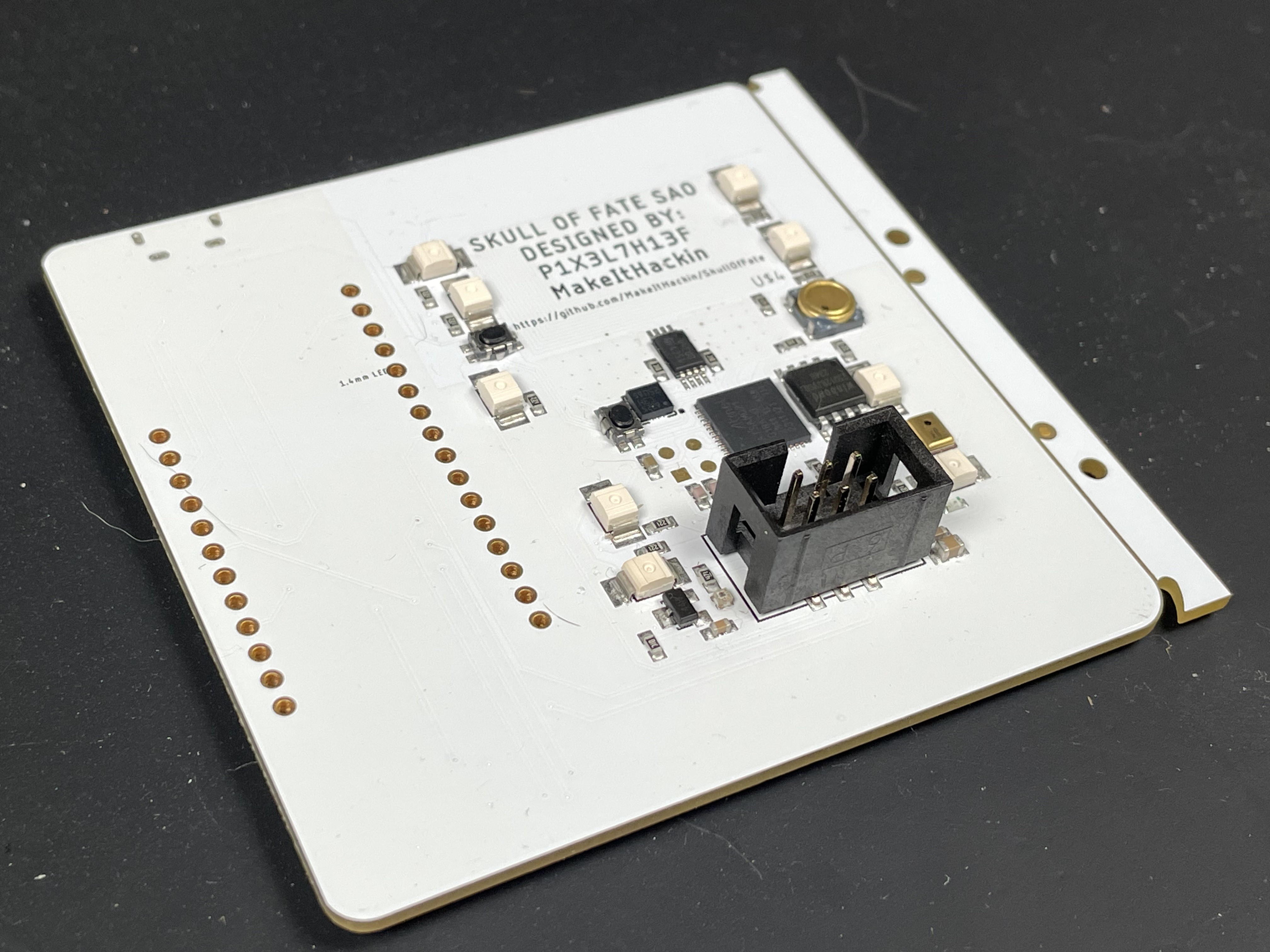
    For v3, we updated the artwork a bit and including some better power handling for the USB vs Supplied Badge power.  Now, the SAO will take power from which ever source has the highest voltage.  So you can safely leave the USB power plugged in as well as supplying power from the badge.

    Otherwise, features, pins, and functionality remains the same as v2

  • v2 Prototype PCB​

    MakeItHackin10/22/2024 at 16:36 0 comments

    v2 Prototype PCB

    The v2 prototype is what you see in the YouTube video demo.  It is fully functional, contains updated artwork, and works really well.
    We decided to update the artwork yet again and still ran into some artwork layer issues with the manufacturer, so we kept learning and used our knowledge to make v3 even better.
    Both eyes in v2 are 1mm x 1mm.  
    We reassigned some pins based on compatibility and included the USB port directly on the SAO.  And it's flush mounted, so no through holes!
    All of our features worked on this version, including the i2c client software!  That was very exciting to test and implement.  See the YouTube video for a demonstration.

  • v1 PCB for SAO

    MakeItHackin10/22/2024 at 16:32 0 comments

    v1 PCB for SAO

    Our v1 prototype was the first to have a custom PCB.  We ordered it fully assembled by JLCPCB and hedged our bets and included a Feather footprint incase we messed up the microcontroller circuitry.  The artwork for v1 was a great start.  And we learned a lot about how PCB manufacturers may alter what your artwork looks like from the computer screen.  Silkscreen will never be put on top of exposed copper, and we found that out the hard way.  Also, we found out the i2c client pins were connected to incompatible pins on the SAO, so we had to revise some of our pin assignments.  We included a piezo buzzer on v1, but removed it because we felt like SAOs shouldn't make noise.  But everything pretty much worked otherwise!   it was an exiting time to receive this board.  We included two sizes of neopixels on v1 to see how they performed.  We decided to stick with the smaller 1mm x 1mm LEDs (seen on left eye)

  • v0 Prototype on Breadboard

    MakeItHackin10/22/2024 at 16:27 0 comments

    v0 Prototype on Breadboard

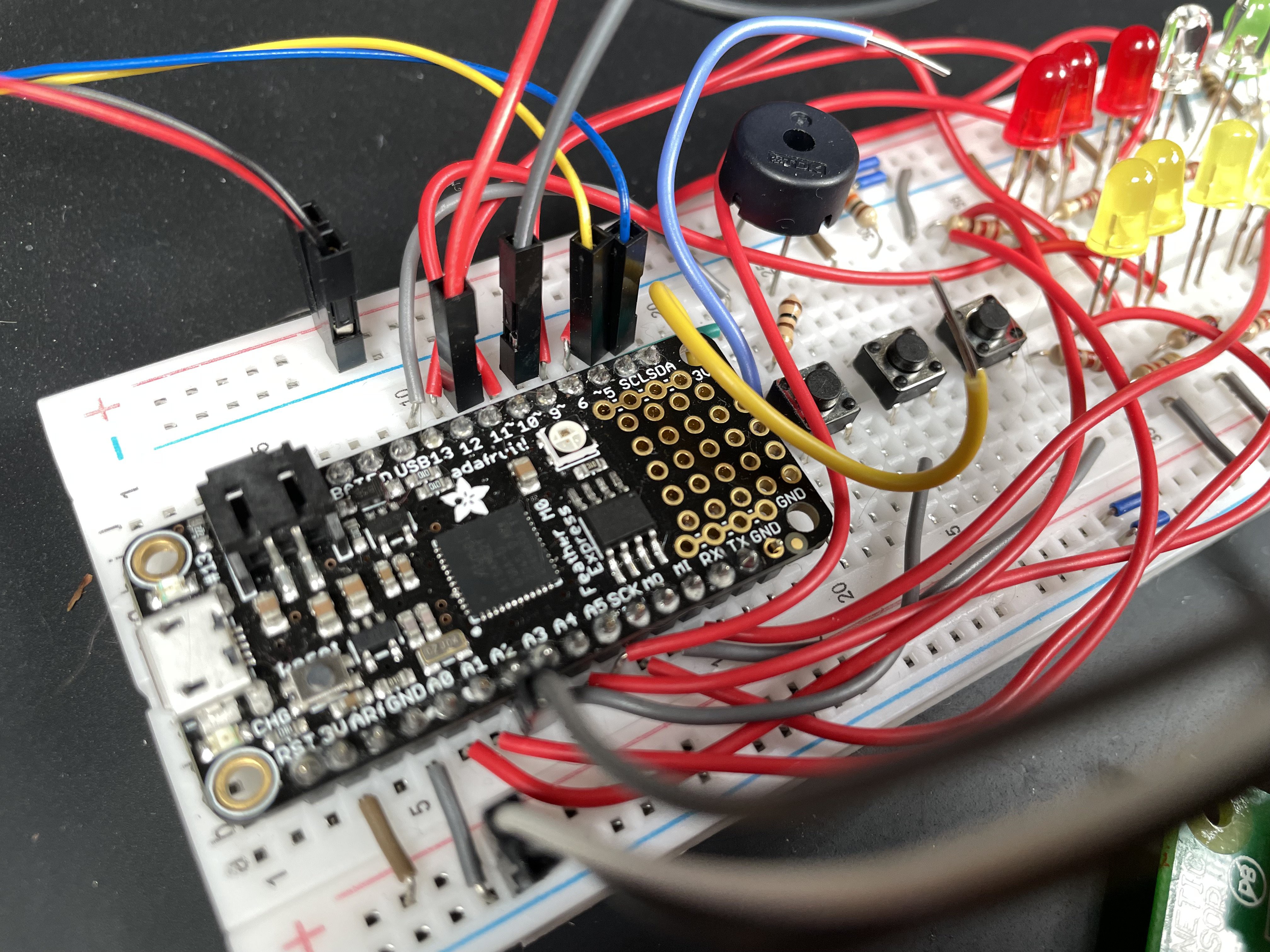
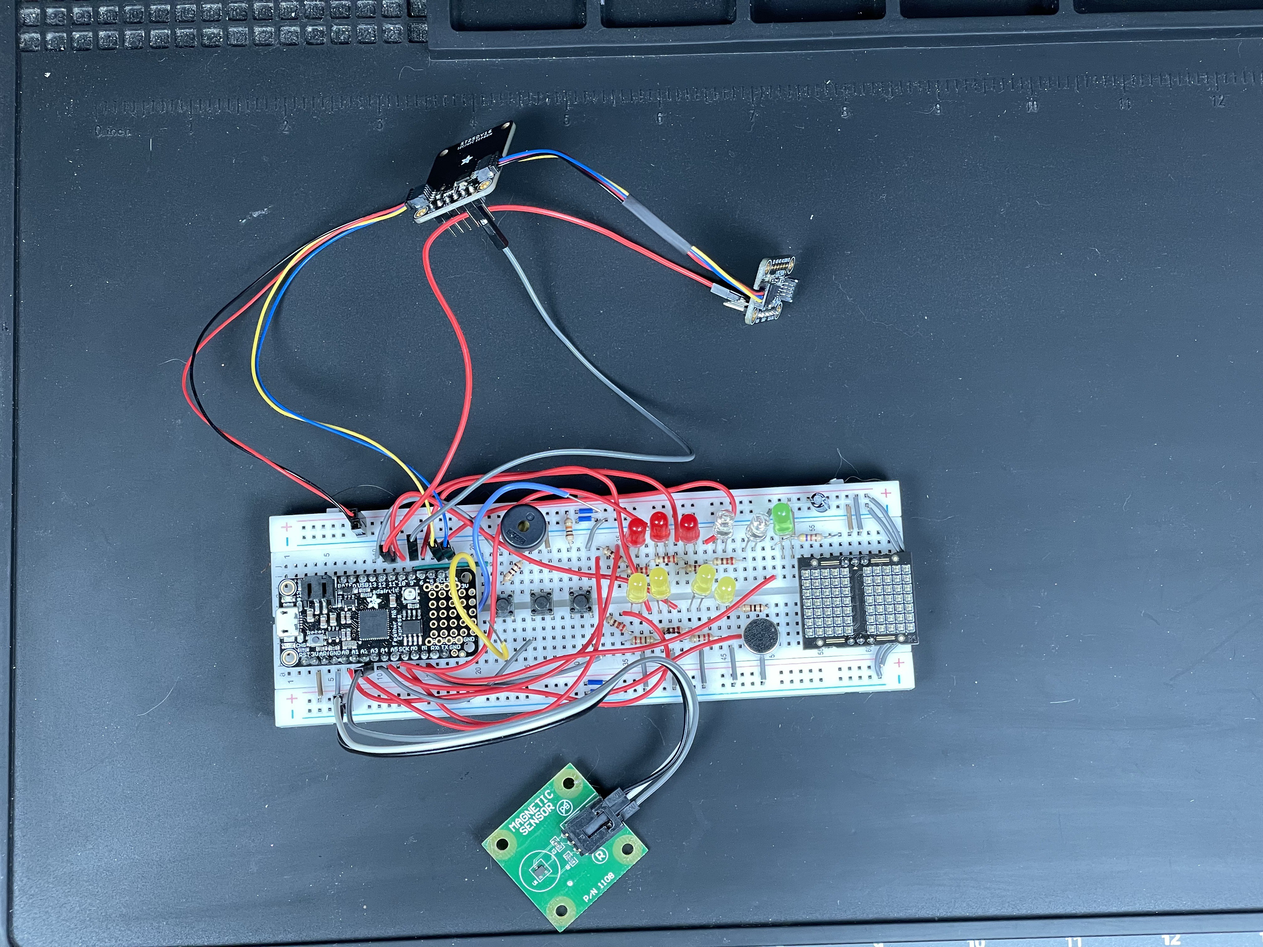
    We decided to build our SAO based on several boards from Adafruit including the Feather M0 Express (as our microcontroller circuit), the LIS3DH accelerometer, and ST25DV breakout board for the RFID.  We used Lixie Labs LEDs for prototyping the eyes.  There were a bunch of wires all over the place, but we learned a lot!  It was our first time using SWD programming, so although it was a little challenging at first, it was pretty easy to flash the microcontroller with Adafruit's Feather firmware.

View all 5 project logs

  • 1
    Building Your Own

    The Gerber files are available and our GitHub will contain updates on how to build your own Skull of Fates SAO

View all instructions

Enjoy this project?

Share

Discussions

M. Bindhammer wrote 10/23/2024 at 14:10 point

Very nice project. More skull PCBs!

  Are you sure? yes | no

Similar Projects

Does this project spark your interest?

Become a member to follow this project and never miss any updates