-
Demonstration Video
10/22/2024 at 16:51 • 0 comments -
v3 Final_Final SAO
10/22/2024 at 16:40 • 0 commentsv3 Final_Final SAO
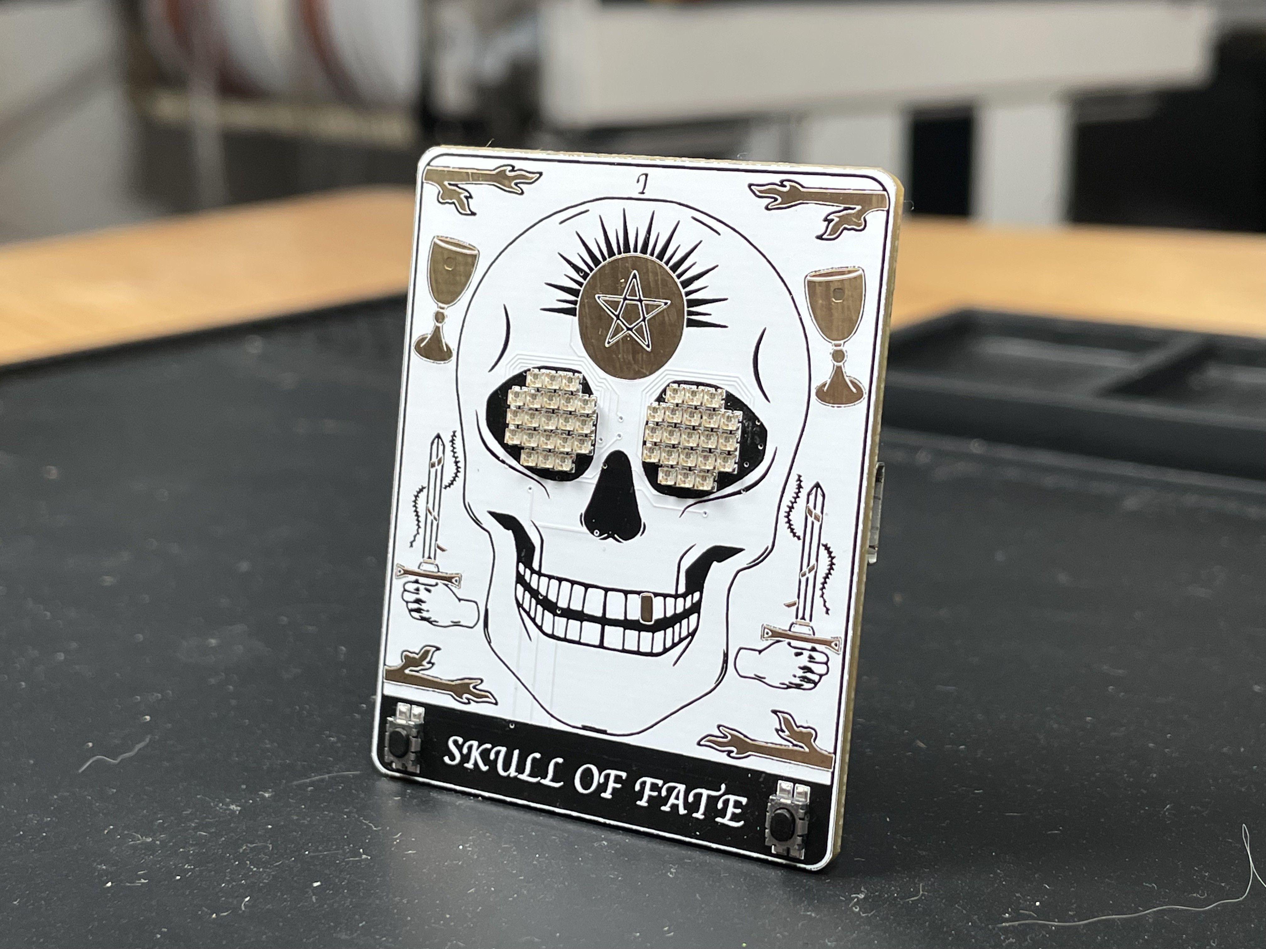
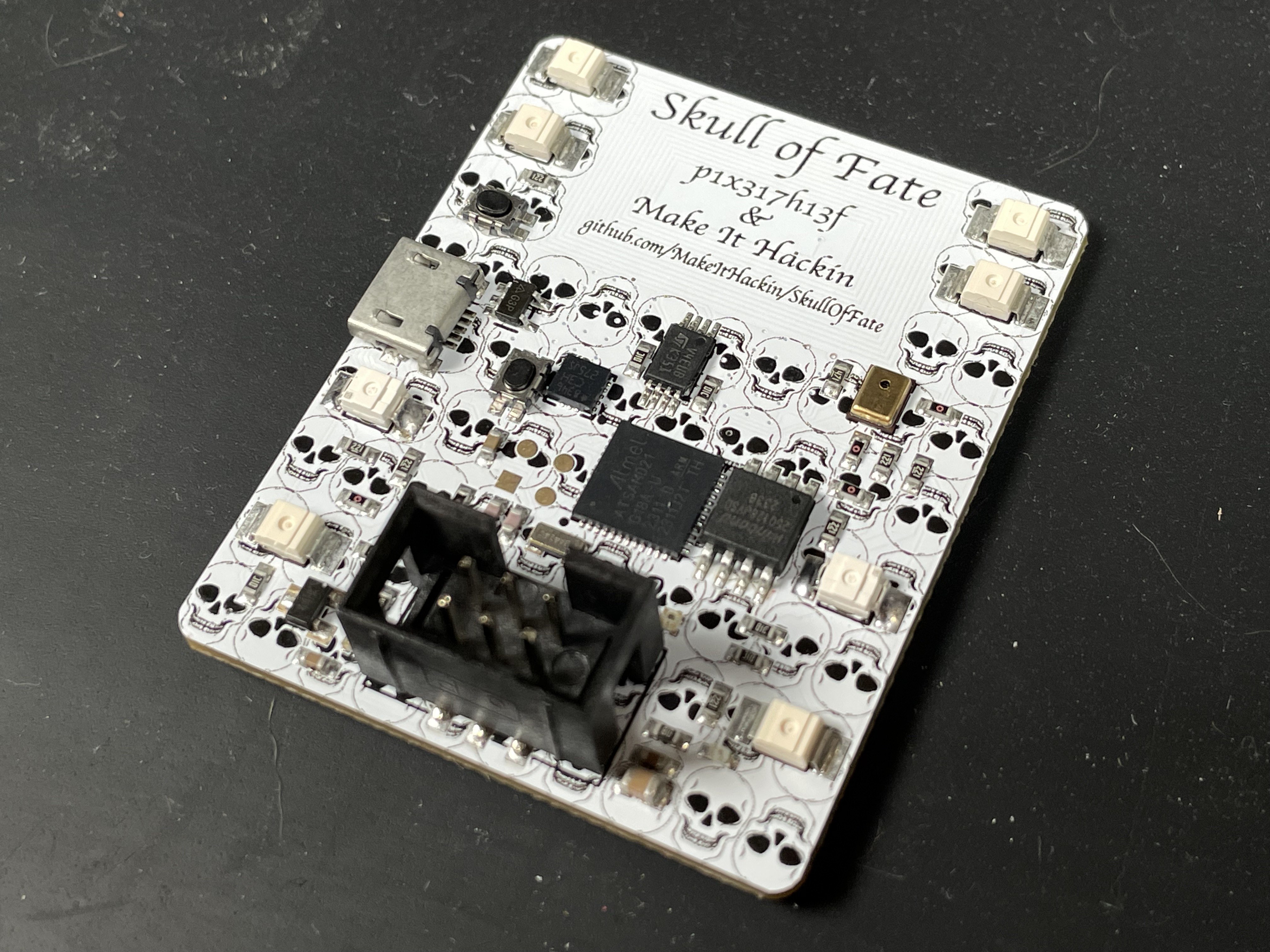
For v3, we updated the artwork a bit and including some better power handling for the USB vs Supplied Badge power. Now, the SAO will take power from which ever source has the highest voltage. So you can safely leave the USB power plugged in as well as supplying power from the badge.
Otherwise, features, pins, and functionality remains the same as v2![]()
![]()
![]()
-
v2 Prototype PCB
10/22/2024 at 16:36 • 0 commentsv2 Prototype PCB
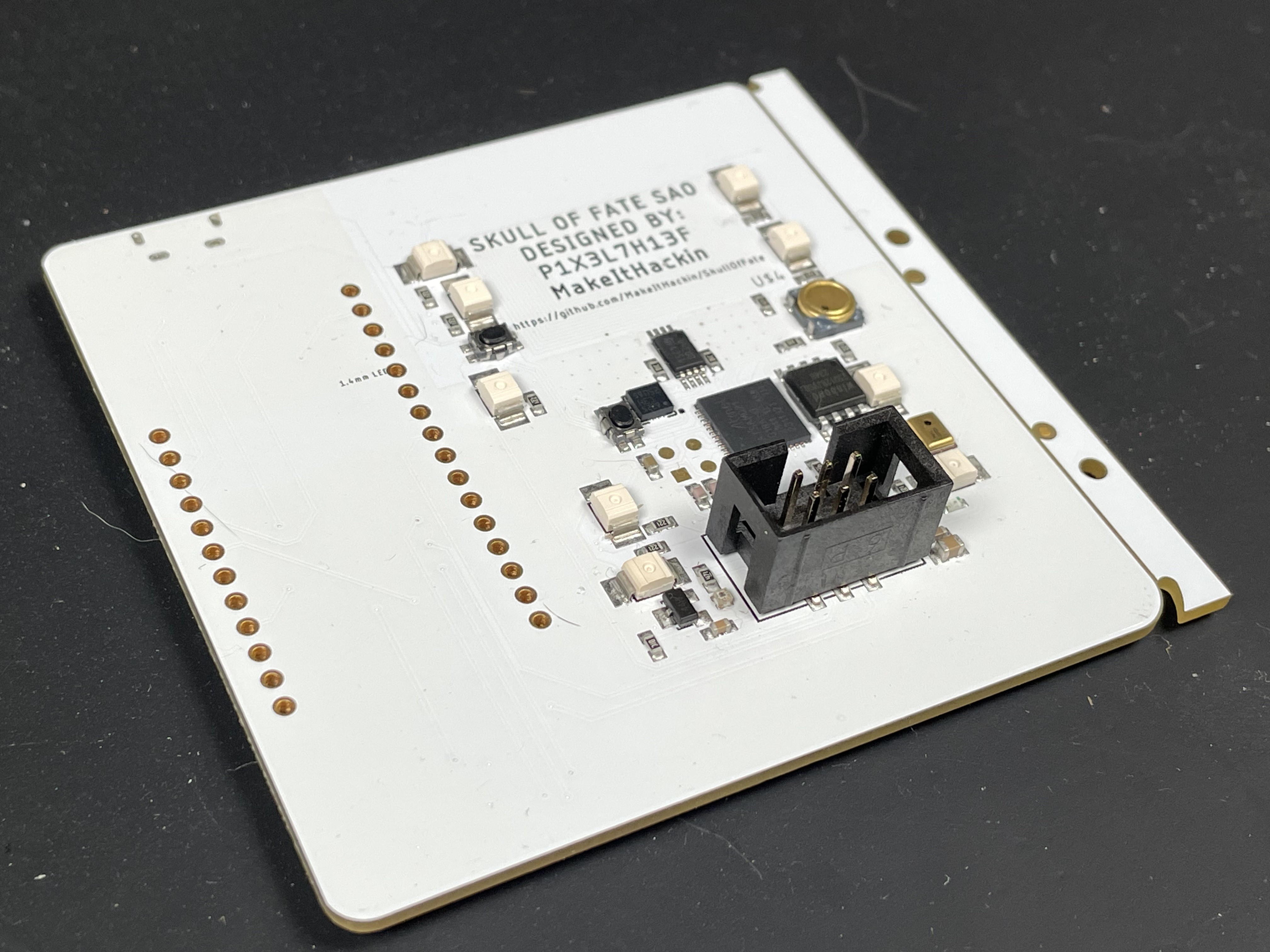
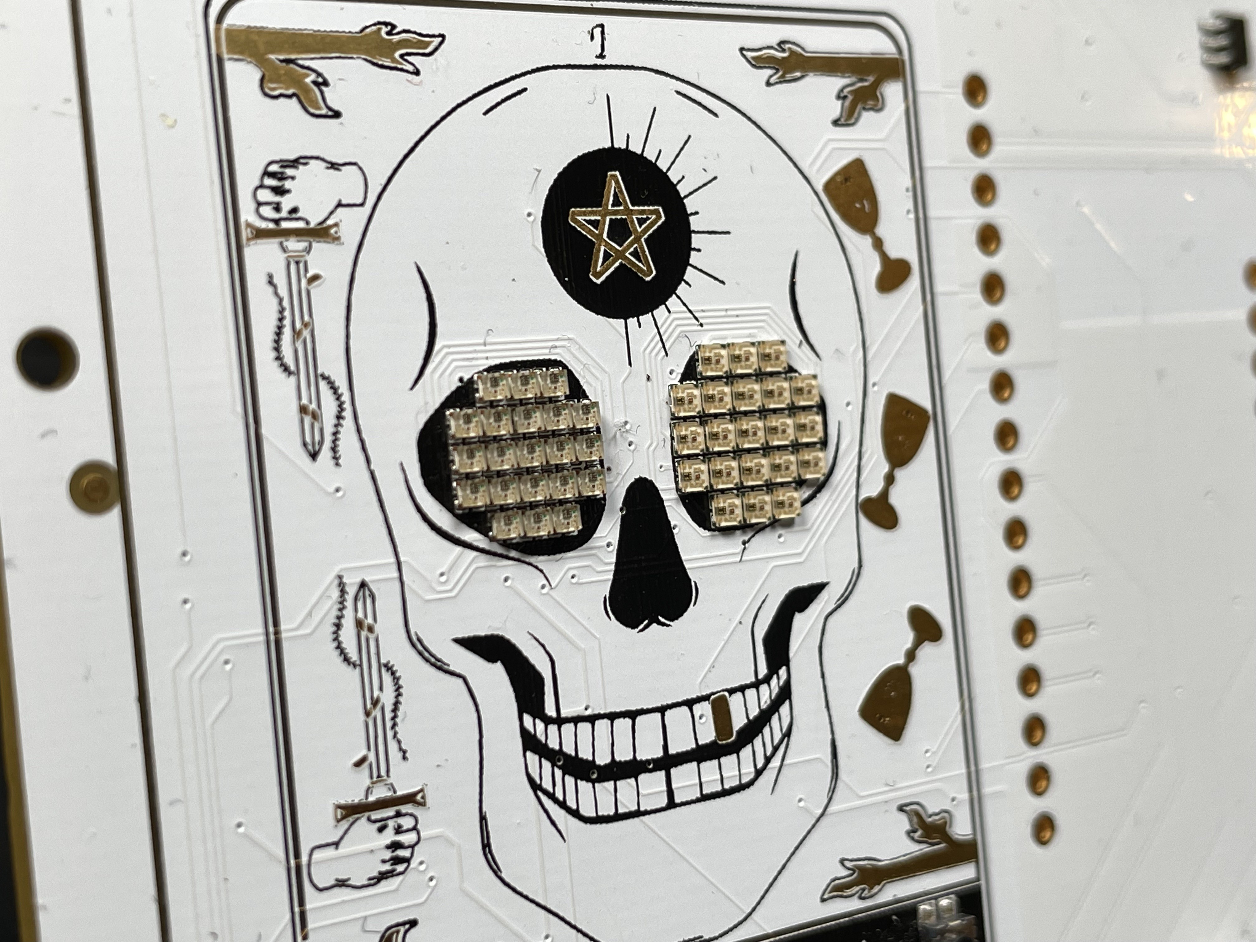
The v2 prototype is what you see in the YouTube video demo. It is fully functional, contains updated artwork, and works really well.
We decided to update the artwork yet again and still ran into some artwork layer issues with the manufacturer, so we kept learning and used our knowledge to make v3 even better.
Both eyes in v2 are 1mm x 1mm.
We reassigned some pins based on compatibility and included the USB port directly on the SAO. And it's flush mounted, so no through holes!
All of our features worked on this version, including the i2c client software! That was very exciting to test and implement. See the YouTube video for a demonstration.![]()
![]()
-
v1 PCB for SAO
10/22/2024 at 16:32 • 0 commentsv1 PCB for SAO
Our v1 prototype was the first to have a custom PCB. We ordered it fully assembled by JLCPCB and hedged our bets and included a Feather footprint incase we messed up the microcontroller circuitry. The artwork for v1 was a great start. And we learned a lot about how PCB manufacturers may alter what your artwork looks like from the computer screen. Silkscreen will never be put on top of exposed copper, and we found that out the hard way. Also, we found out the i2c client pins were connected to incompatible pins on the SAO, so we had to revise some of our pin assignments. We included a piezo buzzer on v1, but removed it because we felt like SAOs shouldn't make noise. But everything pretty much worked otherwise! it was an exiting time to receive this board. We included two sizes of neopixels on v1 to see how they performed. We decided to stick with the smaller 1mm x 1mm LEDs (seen on left eye)
![]()
![]()
-
v0 Prototype on Breadboard
10/22/2024 at 16:27 • 0 commentsv0 Prototype on Breadboard
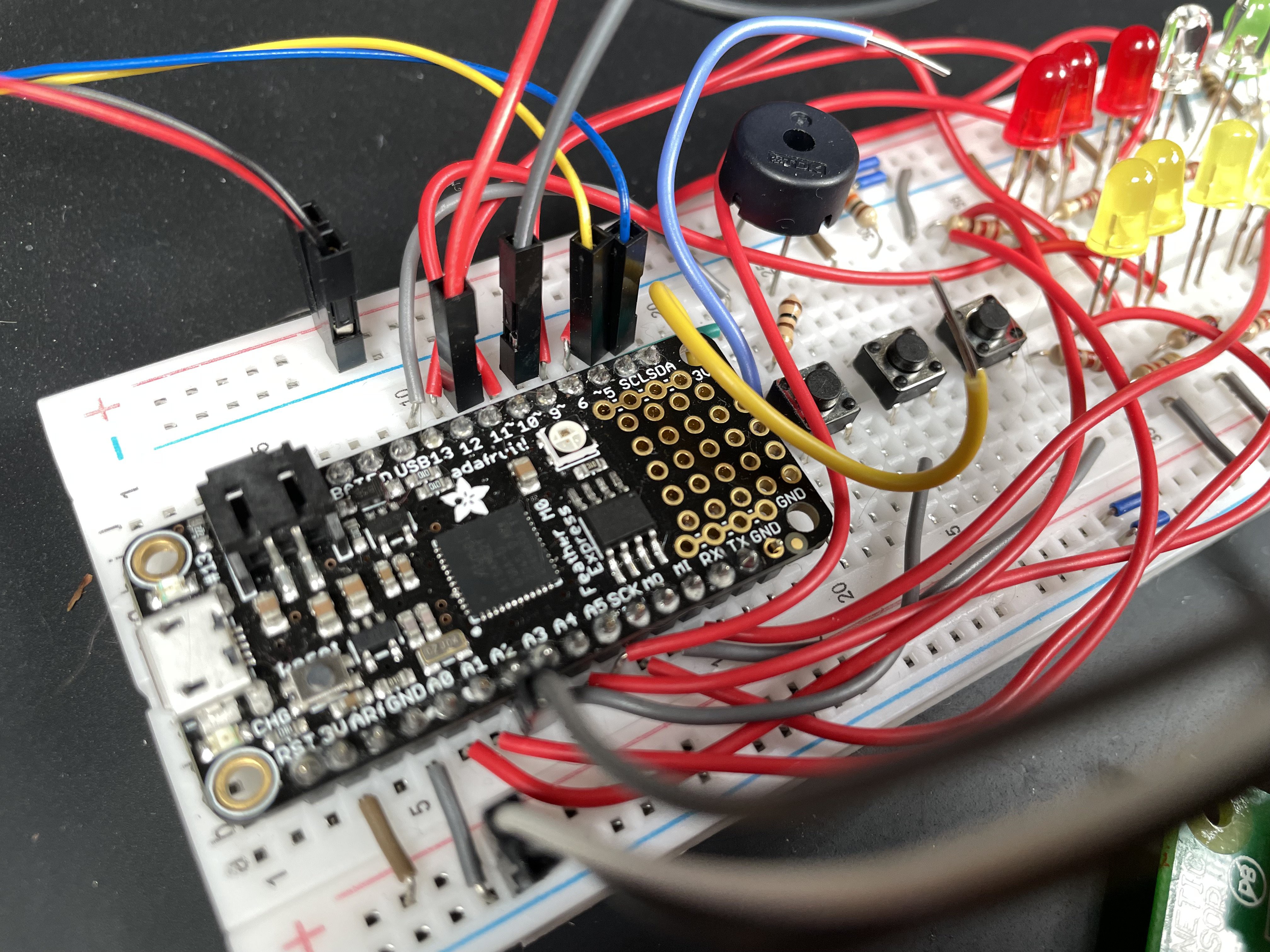
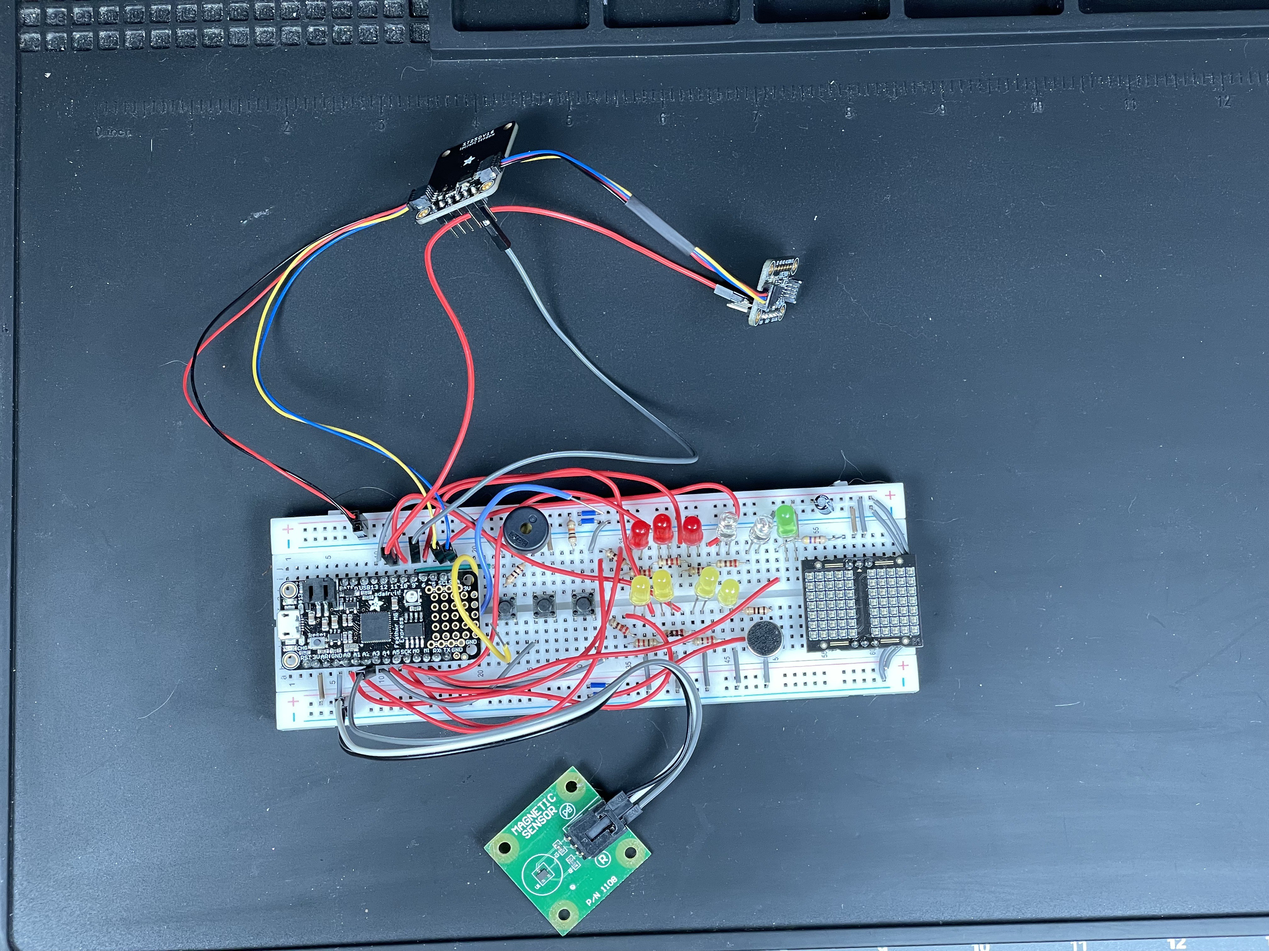
We decided to build our SAO based on several boards from Adafruit including the Feather M0 Express (as our microcontroller circuit), the LIS3DH accelerometer, and ST25DV breakout board for the RFID. We used Lixie Labs LEDs for prototyping the eyes. There were a bunch of wires all over the place, but we learned a lot! It was our first time using SWD programming, so although it was a little challenging at first, it was pretty easy to flash the microcontroller with Adafruit's Feather firmware.![]()
![]()
![]()
![]()
![]()
Skull of Fate SAO
The Skull of Fate SAO is an interactive tarot RFID card featuring i2c host and i2c client capabilities and GPIO interface with the badge.
 MakeItHackin


