3D DESIGN
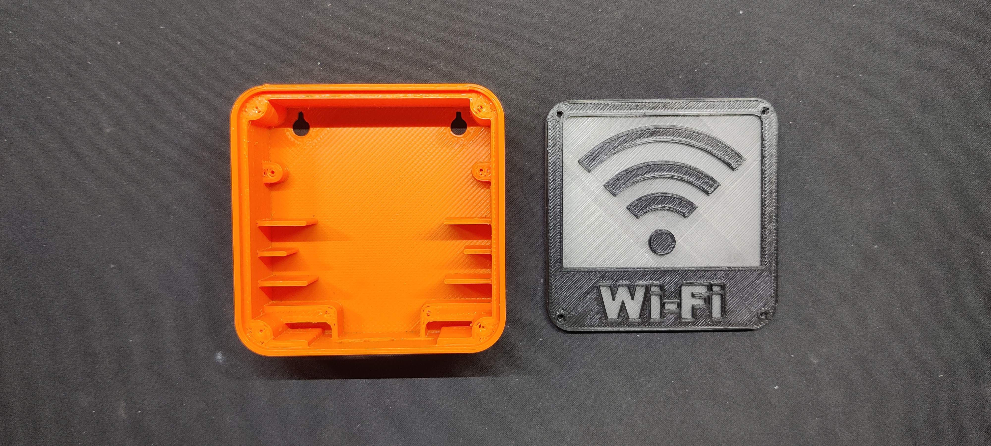
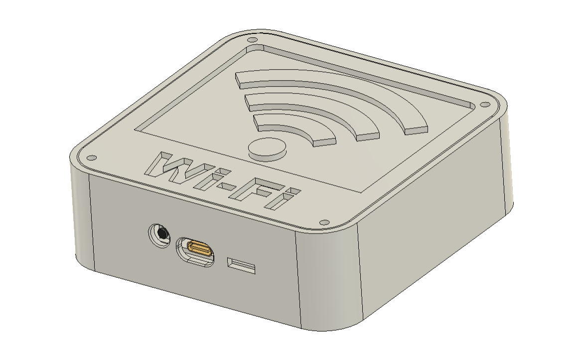
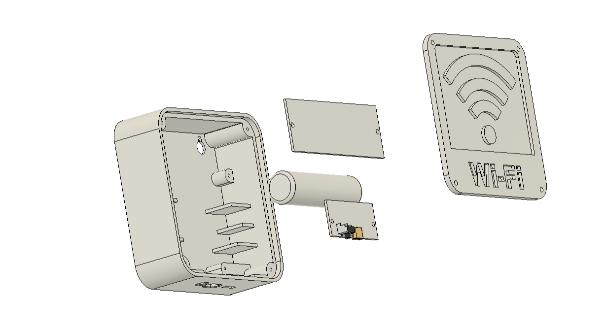
We started by creating the 3D model, which included a small box enclosure with a lid attached to the top side of the enclosure. To secure it to the main body, we inserted four holes into the lid.
We modeled two PCBs inside the enclosure: the power board and the one that will hold the SMD RGB LED and XIAO microcontroller. Additionally, we created a model of the lithium cell that will serve as this project's power source.
Additionally, we designed the ribs that would hold the lithium cell in place and created screw bosses for mounting the power board and the XIAO LED Board.
Our goal was to create two key slots on the bottom side of the enclosure so that it could be mounted on a wall using two nails.
Once the model was complete, we used an Orange PLA 0.4mm nozzle and a 0.2mm layer height to 3D print the enclosure body.
We used two different filament colors to print the enclosure's lid: transparent PLA for the base and black PLA for the Wi-Fi graphics.
CIRCUIT DESIGN
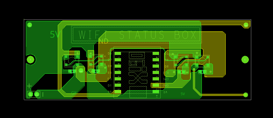

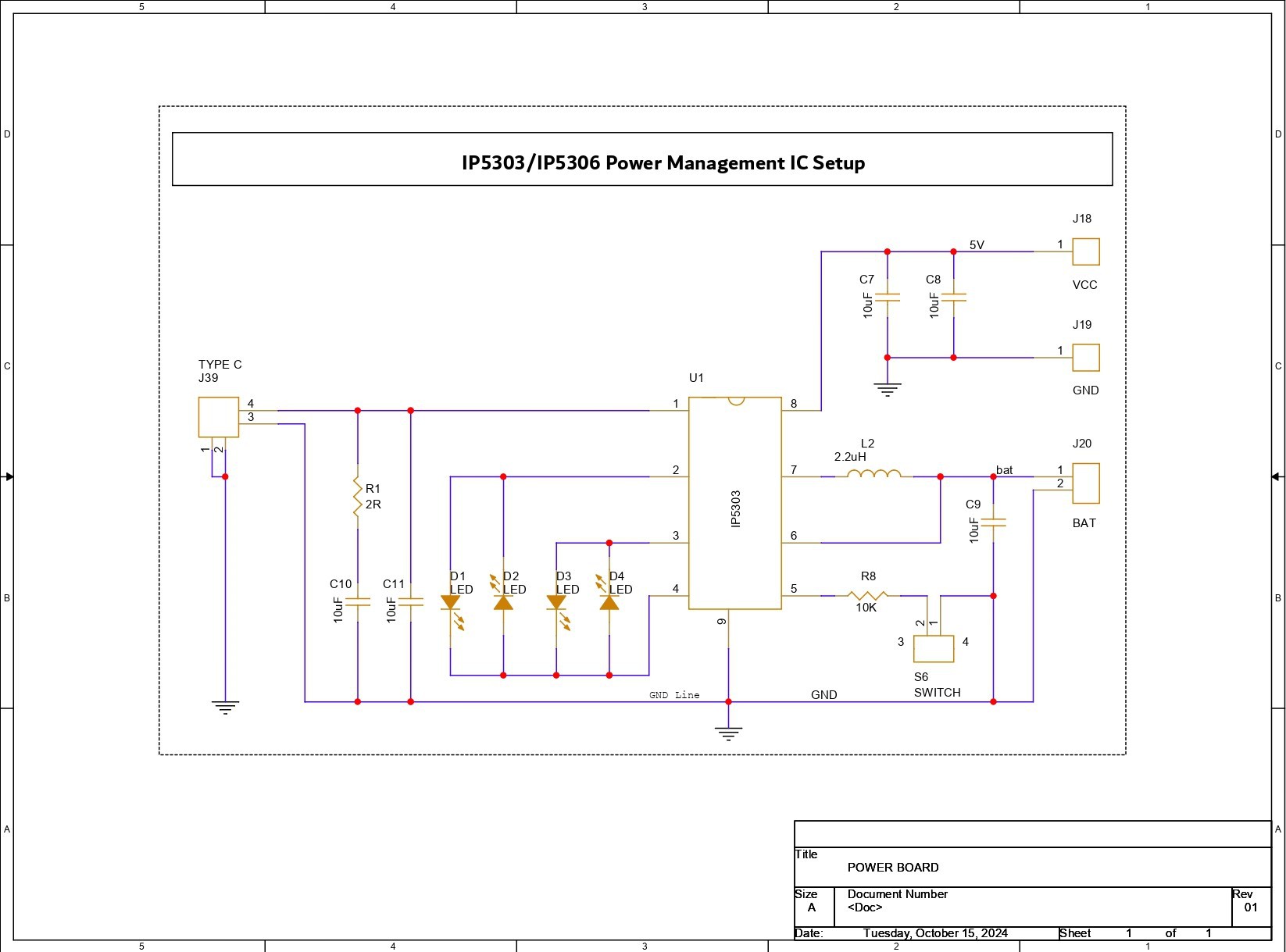
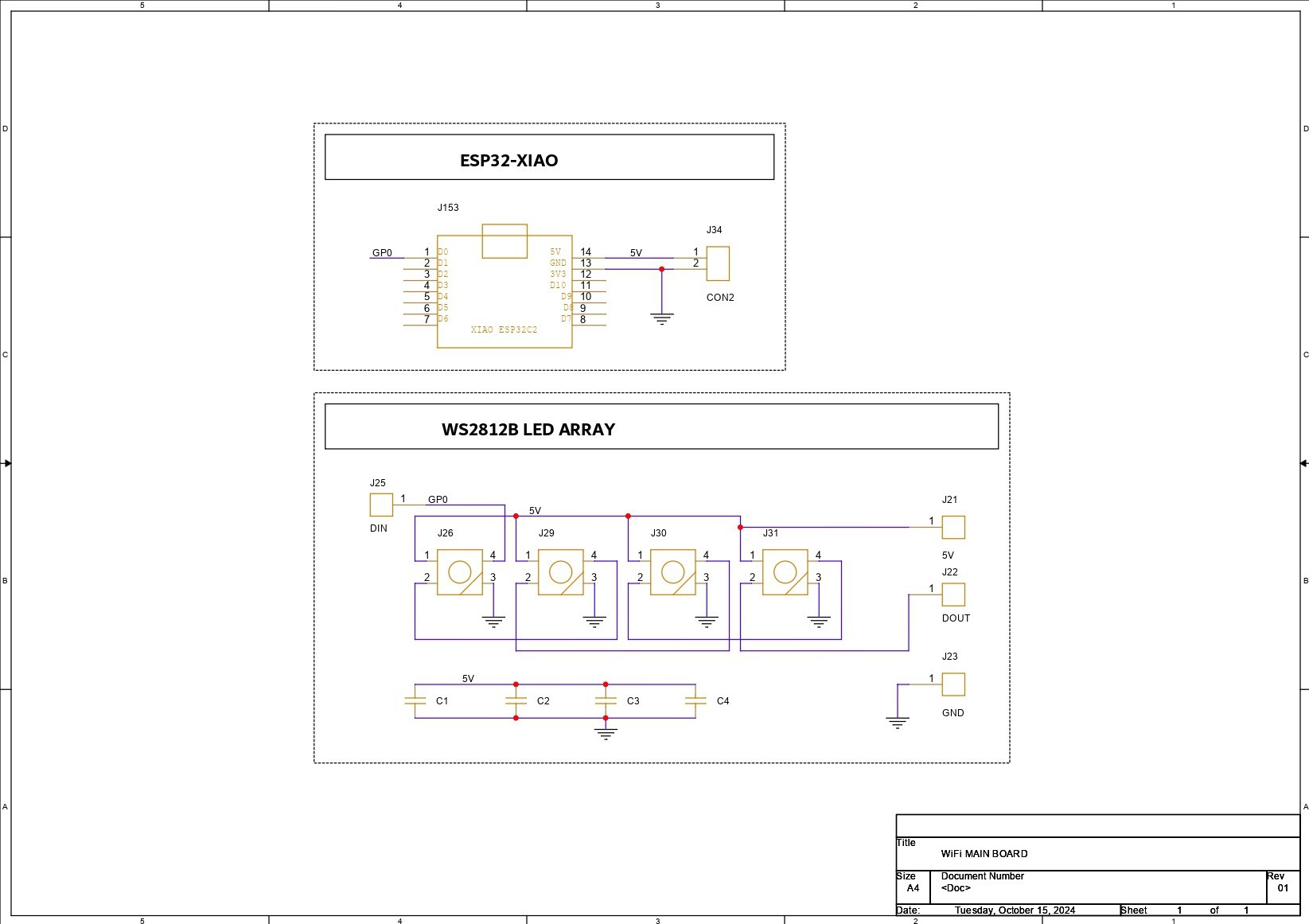

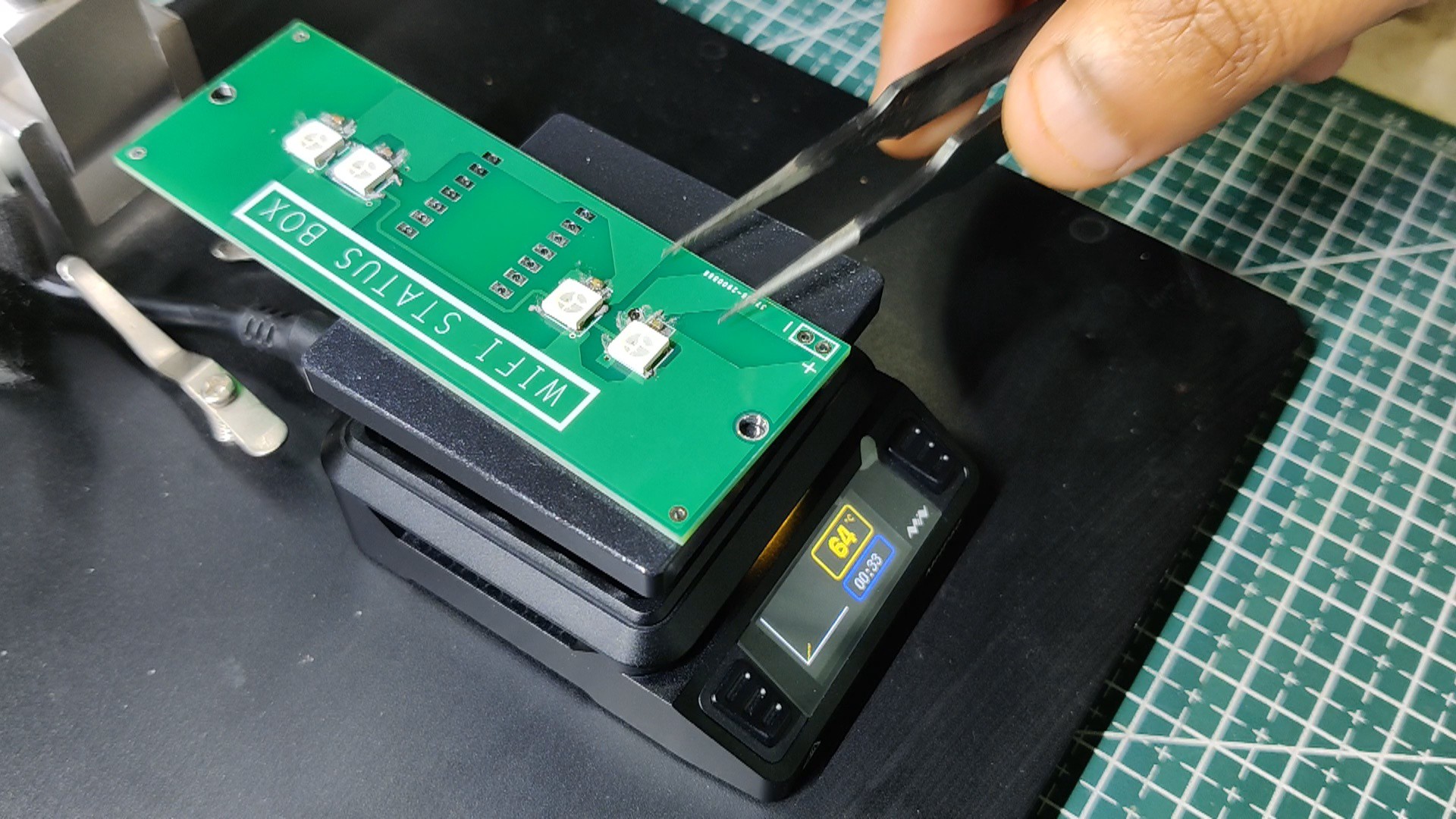
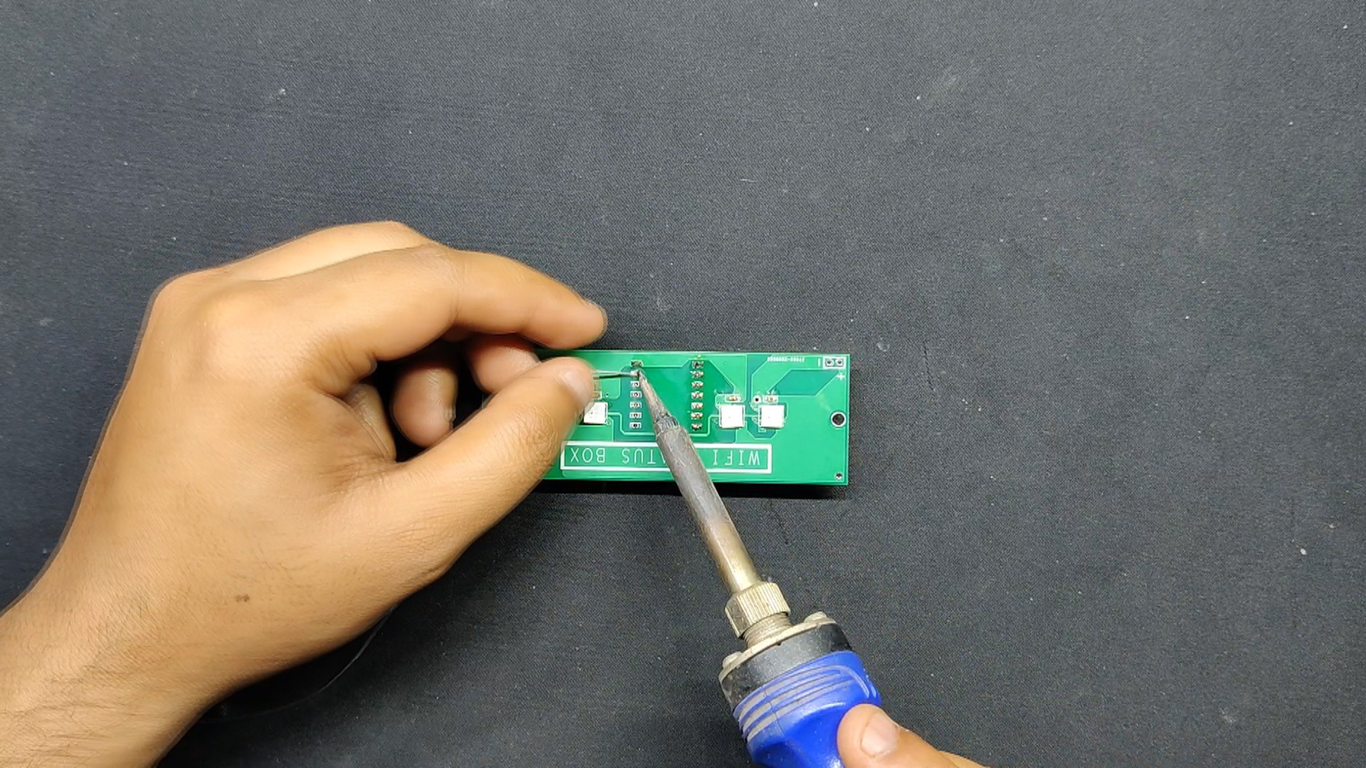
We developed two separate boards for this project: one for the XIAO and WS2812B RGB LEDs, and another for the IP5306 power management IC, which will be used to properly charge and discharge lithium cells and even provide battery indications.
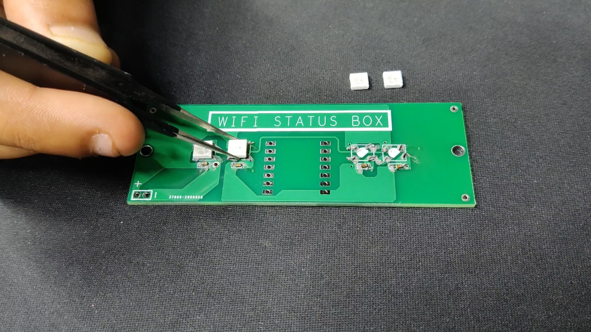
First, let us look at the XIAO RGB Breakout Board. In order to create its schematic, we added the XIAO footprint to the schematic manager together with the WS2812B LED footprint and the decoupling capacitor footprint.
We connected the WS2812B LEDs in their standard configuration, which involves connecting the GND and VCC of each LED in parallel. The first LED's din will be linked to XIAO's GPIO0. The Dout of the first LED will be connected to the Din of the second, the Dout of the second to the Din of the third, and the Dout of the third to the Din of the fourth LED.
After the setup had been completed, we converted the schematic into a board file and made the PCB. We used the Cad file's outline to create the board outline and arrange the components and holes.
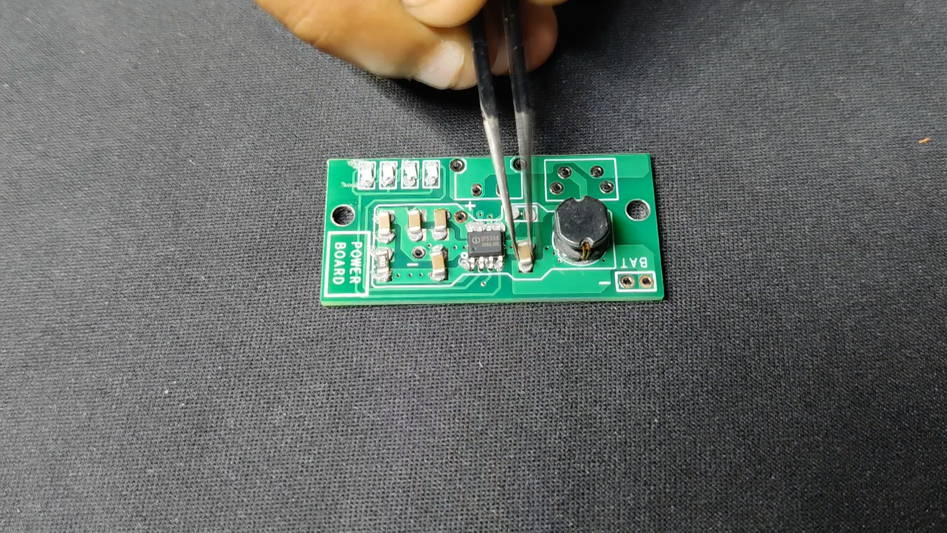
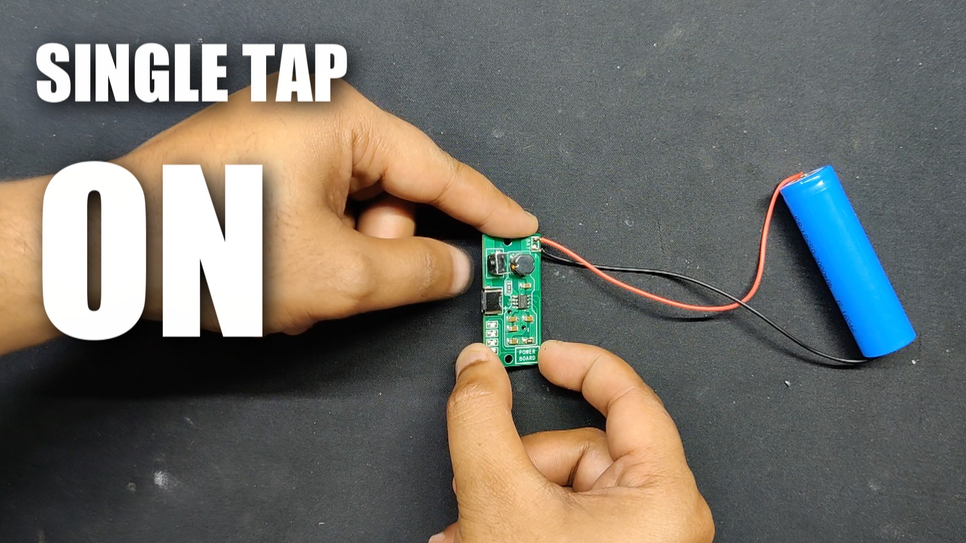
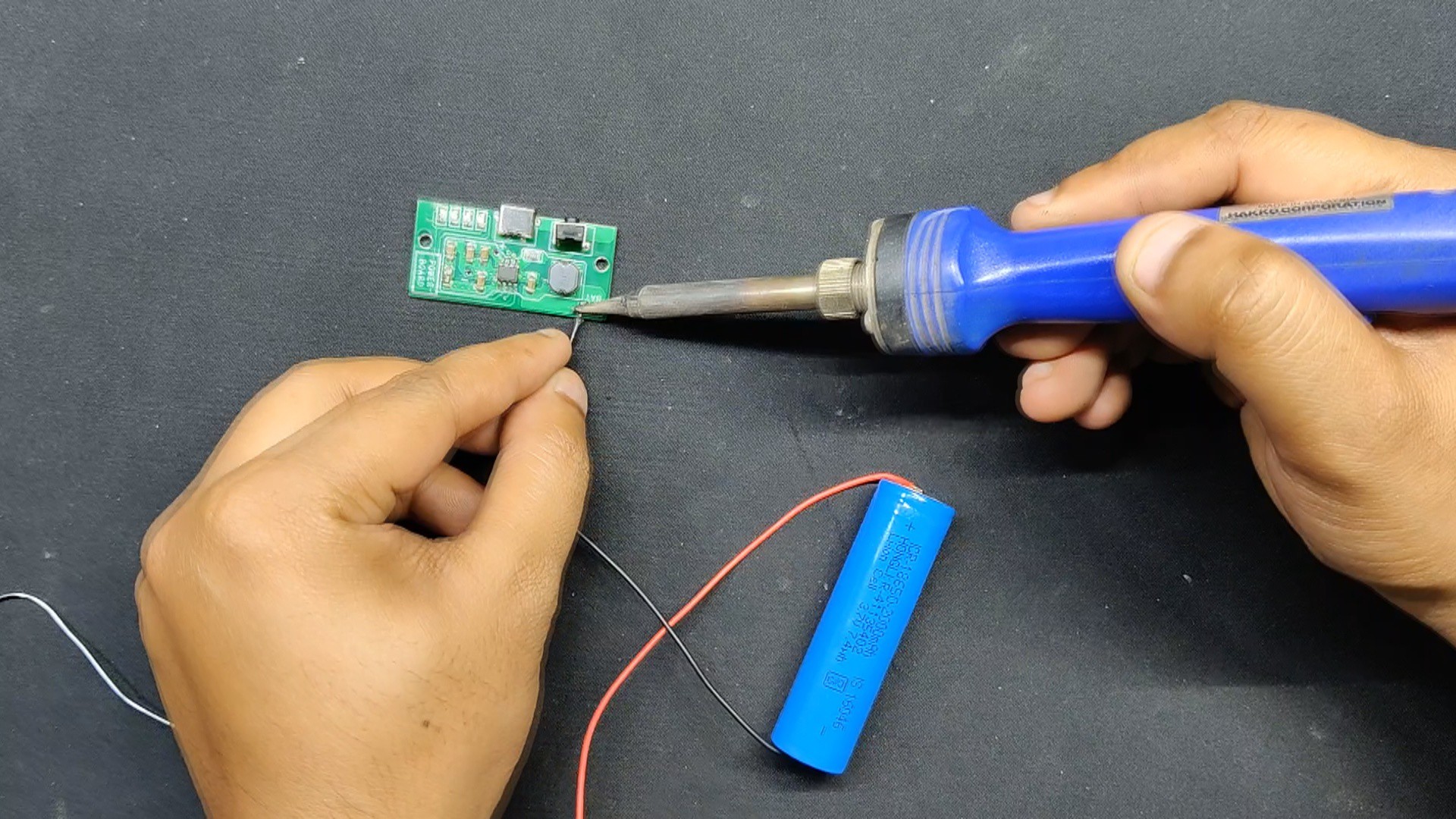
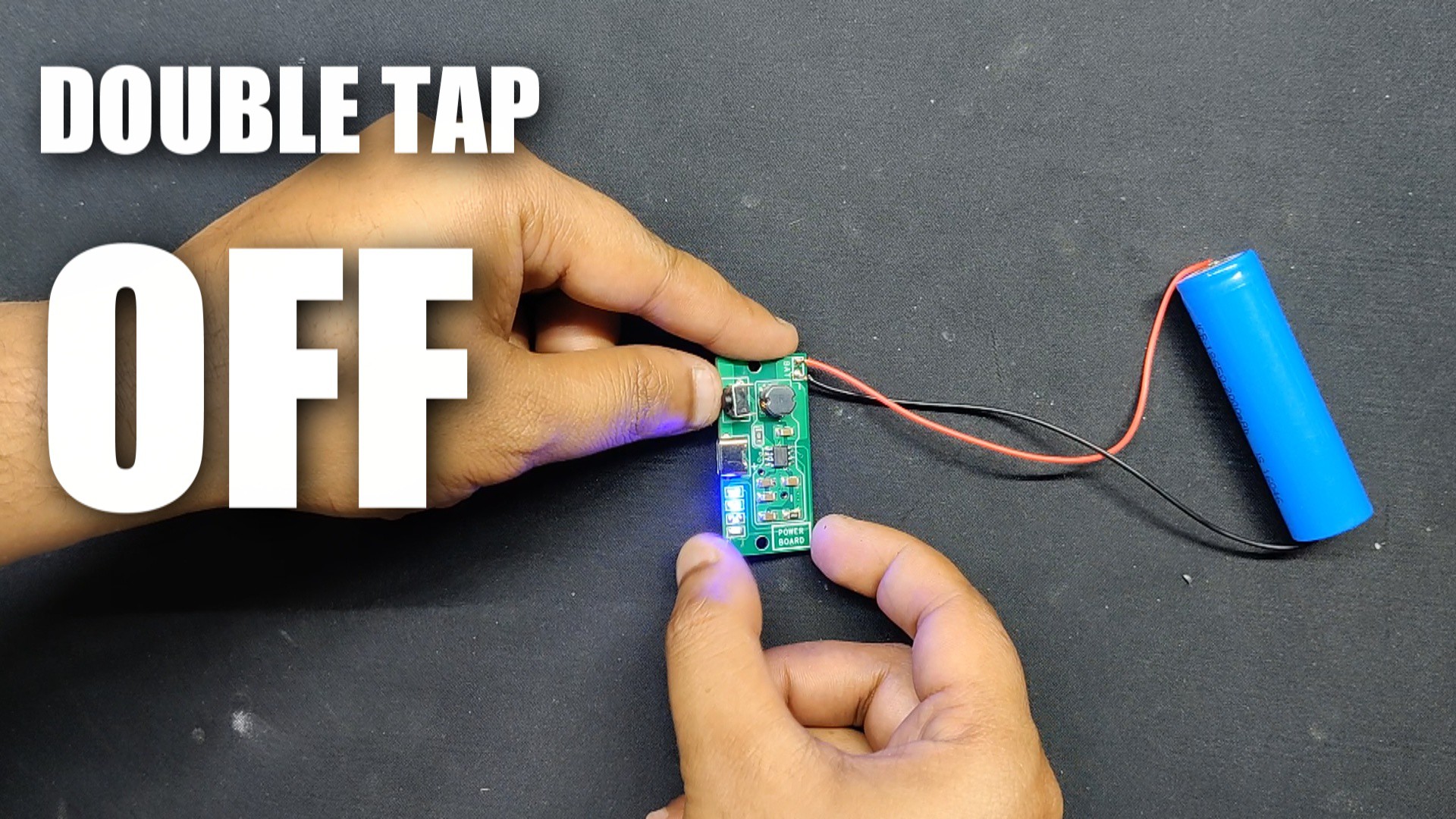
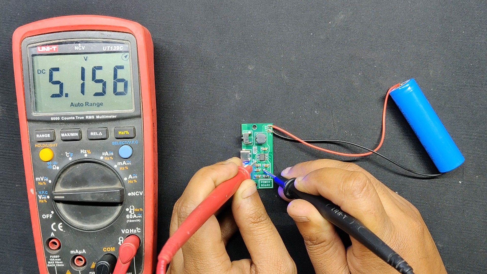
We then created the power board's schematic, which was centered around the IP5306 Power Management IC that provides a steady 5V/2A of power from a 3.7V lithium battery.
After creating the basic layout according to the datasheet, we used a Cad file to add components such as the Type C port, right-angle switch, and LEDs after converting the schematic into a board file.
After finalizing both boards, we exported their gerber data and shared it with HQ NextPCB for samples.
HQ NextPCB Service
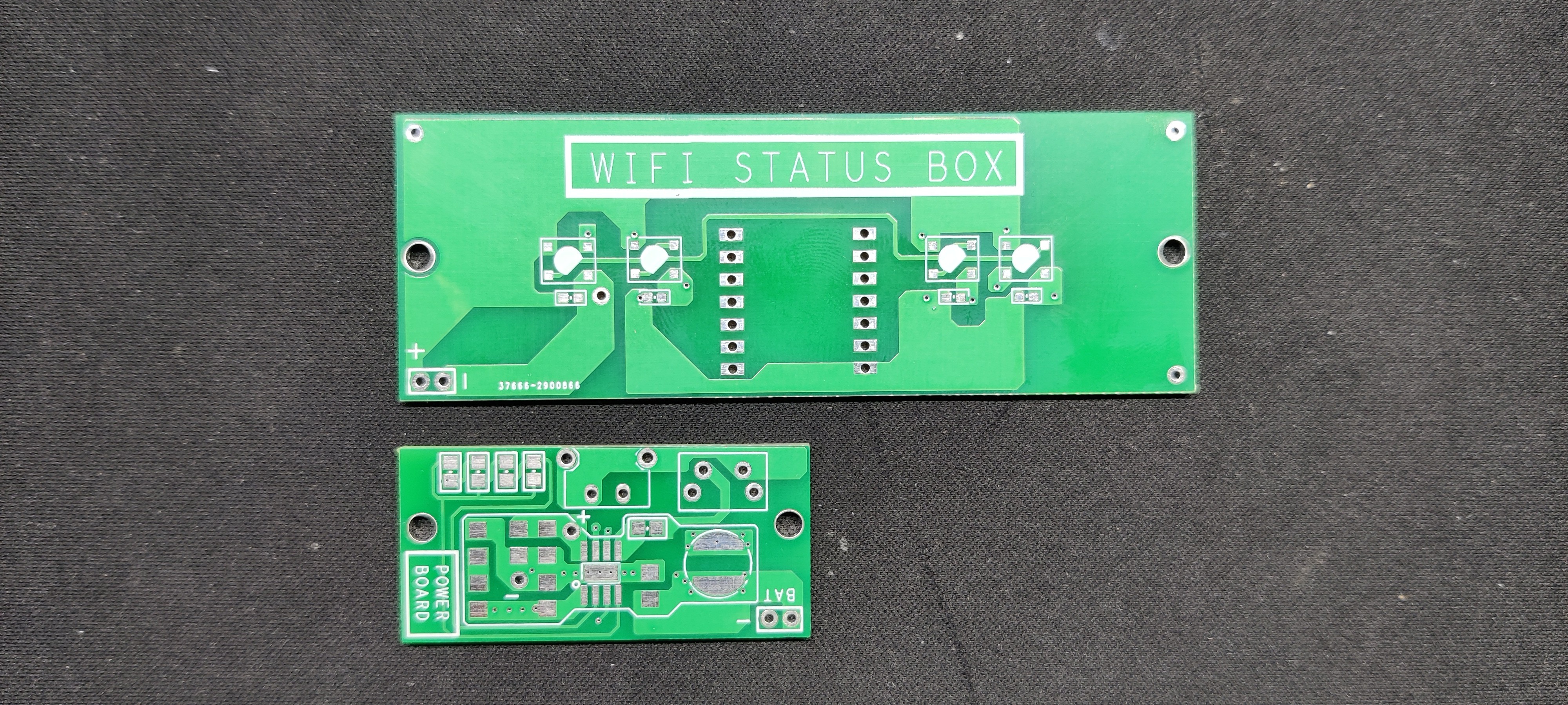
For this project, we chose a green solder mask with white silkscreen for both PCBs.
After placing the order, the PCBs were received within a week, and the PCB quality was pretty great.
In addition, I have to bring in HQDFM to you, which helped me a lot through many projects. Huaqiao's in-house engineers developed the free Design for Manufacturing software, HQDFM, revolutionizing how PCB designers visualize and verify their designs.
HQDFM: Free Online Gerber Viewer and DFM Analysis Tool

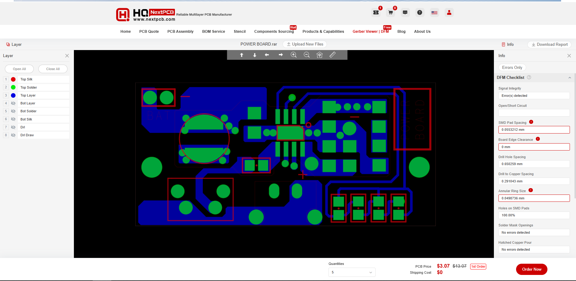
Also, NextPCB has its own Gerber Viewer and DFM analysis software.
Your designs are improved by their HQDFM software (DFM) services. Since I find it annoying to have to wait around for DFM reports from manufacturers, HQDFM is the most efficient method for performing a pre-event self-check.
Here is what online Gerber Viewer shows me. Would not be more clear. However, for full function, like DFM analysis for PCBA, you need to download the software. The online version only provides a simple PCB DFM report.
With comprehensive Design for Manufacture (DFM) analysis features, HQDFM is a free, sophisticated online PCB Gerber file viewer.
It provides insights into advanced manufacturing by utilizing over 15 years of industry expertise. You guys can check out HQ NextPCB if you want great PCB service at an affordable rate.
 Arnov Sharma


 DIY GUY Chris
 Sanjit Sarda