Dan Julio
-
Project in Github
04/11/2025 at 17:17 • 0 commentsI finally had a little time to pull together and document this project. The firmware and hardware designs (currently schematics + gerbers) is in github. I also included the documentation and embedded SDK I got from Infiray.
-
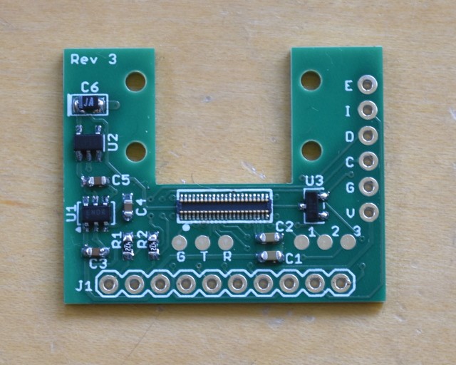
Rev 3 (bodge free!) boards
04/11/2025 at 01:44 • 2 commentsSo I had several bodge wires on the Rev 1 of the iCamCntrl board. I spun it into Rev 2 that integrated the RTC and backup battery. Unfortunately Rev 2 had an issue sensing one of the buttons! Oops, I had a sneak current path. So a quick spin to Rev 3 which works great. I also changed to a different button that can poke through a 3D printed enclosure and moved the charge LED to under the USB connector.
![]()
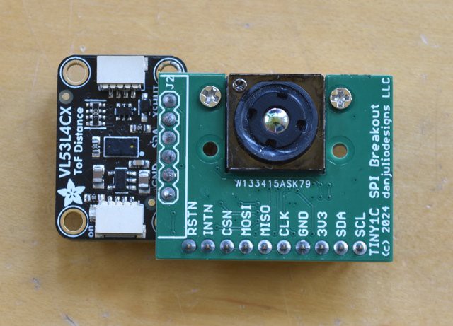
At the same time I took the opportunity to include a header for the VL53L4CX TOF sensor so it could be both close to the Tiny1C and more easily aligned so it "sees" close to the center of the Tiny1C image.
![]()
![]()
I use a Qwiic cable to connect to the AHT20 sensor so it can be slightly removed from the camera board to more accurately sense ambient temperature. Ideally in a case it would be isolated from the camera with air flow across it.
![]()
-
MDNS camera discovery - no more remembering IP addresses
01/17/2025 at 03:00 • 0 commentsHaving to remember (or find a DCHP served) IP address and then type it into the browser is frustrating. At some point as the firmware came together I had one of those "Oh Doh!" moments where you remember something important. The Espressif IDF provides a Multicast DNS (mDNS) library that runs on their network stack. I had actually used this in the tCam project but hadn't used it there for domain resolution.
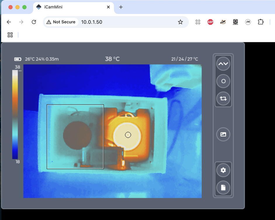
With mDNS the iCamMini can be found by typing the URL "icam.local" in the browser. The ".local" suffix tells the browser use mDNS to try to find the domain on the local network. Then the iCamMini replies with its address and the browser opens the default page at that address.
While you can still access the camera using its IPV4 address (e.g. http://10.0.1.50), this makes it easy to find cameras given a DHCP address or when you move the camera to a new network or make it mobile by having it act as the AP point.
![]()
It's actually easy to implement. The routine I use to start mDNS after the network comes up is shown below.
static bool start_mdns()
{
char s[16];
const esp_app_desc_t* app_desc;
esp_err_t ret;
esp_netif_ip_info_t ip_info;

// Attempt to initialize mDNS
ret = mdns_init();
if (ret != ESP_OK) {
ESP_LOGE(TAG, "Could not initialize mDNS (%d)", ret);
return false;
}

// Set our hostname
ret = mdns_hostname_set("icam");
if (ret != ESP_OK) {
ESP_LOGE(TAG, "Could not set mDNS hostname (%d)", ret);
return false;
}

// Set our default instance
ret = mdns_instance_name_set(wifi_config.ap_ssid);
if (ret != ESP_OK) {
ESP_LOGE(TAG, "Could not set mDNS instance %s (%d)", wifi_config.ap_ssid, ret);
return false;
}

// Get info for our TXT records
app_desc = esp_app_get_description();  // Get version info
esp_netif_get_ip_info(wifi_netif, &ip_info);  // Get IP address
sprintf(s, IPSTR, IP2STR(&ip_info.ip));

service_txt_data[0].key = txt_item_keys[0];
service_txt_data[0].value = s;
service_txt_data[1].key = txt_item_keys[1];
service_txt_data[1].value = app_desc->version;

// Initialize service
ret = mdns_service_add(NULL, "_http", "_tcp", 80, service_txt_data, NUM_SERVICE_TXT_ITEMS);
if (ret != ESP_OK) {
ESP_LOGE(TAG, "Could not initialize mDNS service (%d)", ret);
return false;
}

mdns_running = true;
return true;
}
Aside from initializing the library and giving the device the name "icam" the important bit is the mdns_service_add() at the bottom. It tells the library to respond to requests from a browser. The TXT records contain the camera's IP address and firmware version. TXT records are additional information that is present along with the response. Normally the browser doesn't care about these but a general purpose mDNS browsing utility will display them.
-
GUI
11/20/2024 at 22:45 • 2 comments(pretty pictures below if this is TL;DR)
I'm using LVGL for the iCam and iCamMini Web GUIs. The video output uses a much simpler set of 8-bit monochrome drawing routines since LVGL doesn't really support 8-bit monochrome. I chose LVGL for the web interface because I don't really know traditional web programming but am experienced with LVGL and can use emscripten to compile a C program into WebAssembly that would run in any modern browser. The LVGL people already use emscripten to publish live demos in their HTML documentation so it was easy to figure out how to build. The result looks slightly different than traditional web page layouts but it works.
The part I'm proud of is creating a view/model-controller paradigm that let me write essentially one set of GUI code works both on the embedded (SPI-accessed) 3.5" gCore LCD and also in a browser. When running in the browser it can resize and react to events like rotation of a mobile device to change its layout dynamically. The connection between the GUI view and model-controller is done through a set/get/response API that maps to direct function calls when the GUI is running on the same platform as the model-controller and serialization/de-serialization through a websocket when the GUI is running in the browser. For example the GUI might issue a GET EMISSIVITY command to update the emissivity control panel. This ends up executing a get_emissivity_handler() subroutine. The subroutine is executed directly by the API on the combined platform and as the result of parsing an incoming websocket packet on the remote platform.
I do take a few performance short-cuts. For example the actual thermal image is a 256 x 192 x 8-bit scaled raw image chunk of data. All 49,152 bytes (+ some additional data) have to get sent over the websocket by iCamMini. But on the iCam platform I only pass a 4-byte pointer to a shared data structure instead of copying the data.
I say the GUI can automatically adjust to the screen but there are limits. In all cases during my layout I had to make sure it would fit on the relatively constrained iCam 480x320 pixel LCD. For performance reasons I picked fixed 1.5x or 2.0x magnification of the image (so I could use some very optimized bi-linear interpolation code) and this sets how big the display can be on a desktop browser. In other cases I adjust limits so the various screens look good on a mobile phone. I have yet to do testing on a tablet so it's possible further optimizations might be necessary.
When running on an iCamMini, the code starts the Espressif web server which serves a single large html page to the first connected client. This page contains a very small amount of HTML and CSS and the big WebAssembly binary (> 400kB) that runs when the page loads. It initiates a websocket connection with the server and from then on all commands and data pass through that. The web LVGL drivers render to a javascript canvas using SDL.
The WebAssembly code is its own program and can run even when the iCam is disconnected from it for some reason. For this reason I am attempting to catch various disconnect scenarios or have iCamMini inform the GUI when it is powering down so the GUI can display a default page indicating it's disconnected (and has a reconnect button).
All C code is contained in a single project structured for the Espressif IDF build environment. The majority of the code is shared between the two cameras with only some custom device-specific code. I have a script which sets specific sdkconfig files for each camera type and the linker is configured to only include necessary code. There is another directory that is ignored by the IDF tools but is where I build the emscripten code. It contains its own main.c file which is the WebAssembly LVGL GUI program. There are links back to the IDF components directories holding the LVGL GUI code. In this way the same GUI source is built for two different platforms. All-in-all the code base builds 3 binaries:
- iCamMini ESP32 code
- iCamMini WebAssembly code (which is included in the ESP32 code ultimately)
- iCam ESP32 code
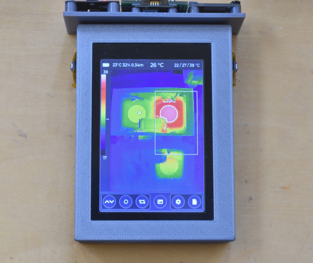
But enough of this wall of text. Here are some actual screens. The main screen can render in a landscape or portrait orientation.
![]()
![]()
![]()
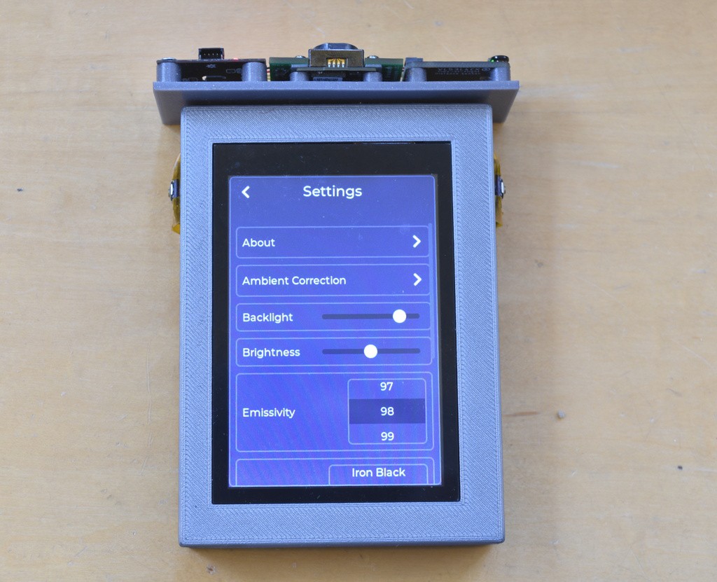
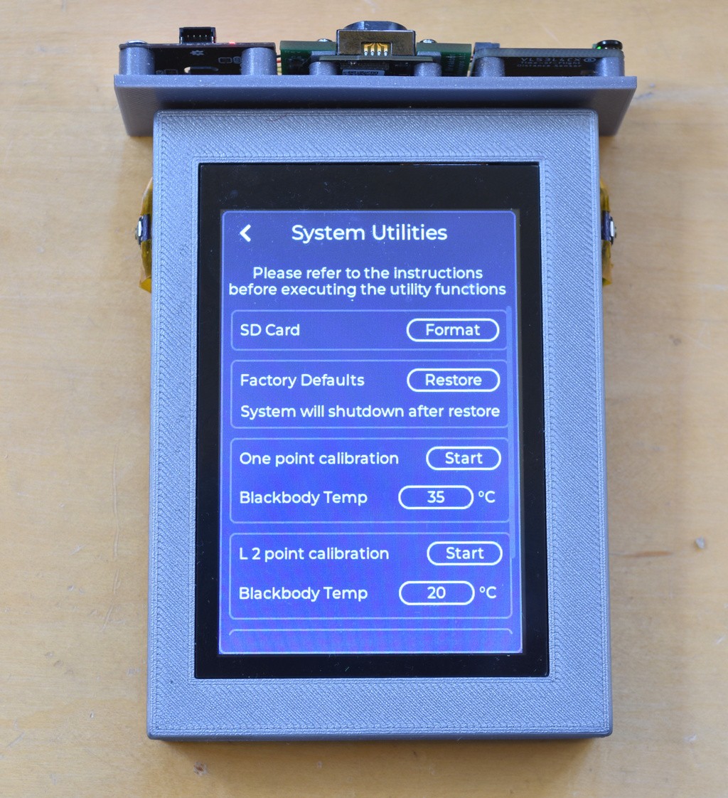
The settings page is a scrollable container of panels, one panel for each control or related set of controls (which are drawn on another screen). Navigation between settings screens is done via the typical ">" and "<" buttons.
![]()
![]()
![]()
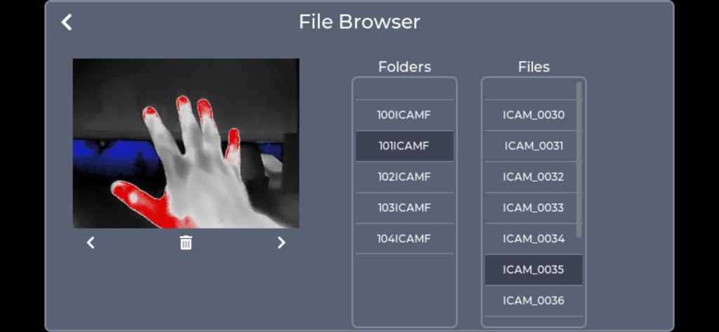
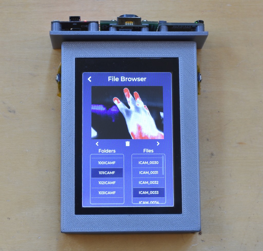
Finally there is a simple File Browser screen that allows viewing the JPG images saved on the Micro-SD card. Here shown as a mobile screen shot and on iCam.
![]()
![]()
I'm following the traditional digital camera DCIM directory structure with a set of folders (NNNICAMF) each containing up to 100 images (ICAM_NNNN.JPG). I limit the number of files in a folder to help speed the underlying filesystem code running on the ESP32. An astute observer may wonder why, then, I have a file with the number 30 in the 2nd folder. This is because during testing I varied the number of files to test some boundary conditions in the code that generates the filesystem catalog.
-
iCamMini Prototype
11/20/2024 at 03:05 • 1 commentMy vision for iCamMini is for a remotely accessed camera. For example to be flown on a drone or remotely operated vehicle or to be mounted (suitably protected) outdoors or on a lab bench monitoring a circuit while the user sits at a computer. The video interface can be connected to a long-range transmitter or the camera can be accessed via Wi-Fi for shorter range applications.
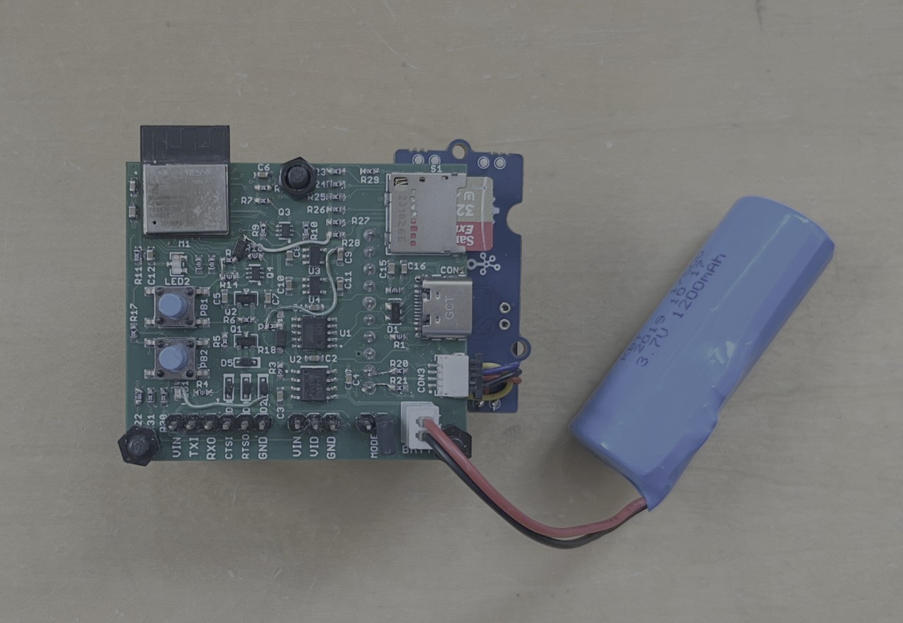
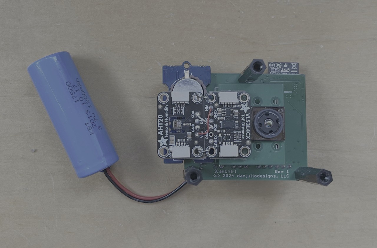
The prototype consists of a baseboard I designed called iCamCtrl and a Tiny1C breakout board. I didn't originally design-in a RTC chip so a PCF85063-based breakout from Seeed Studio was added and I directly soldered the AHT20 and VL53L4CX breakouts to the Tiny1C board.
![]()
![]()
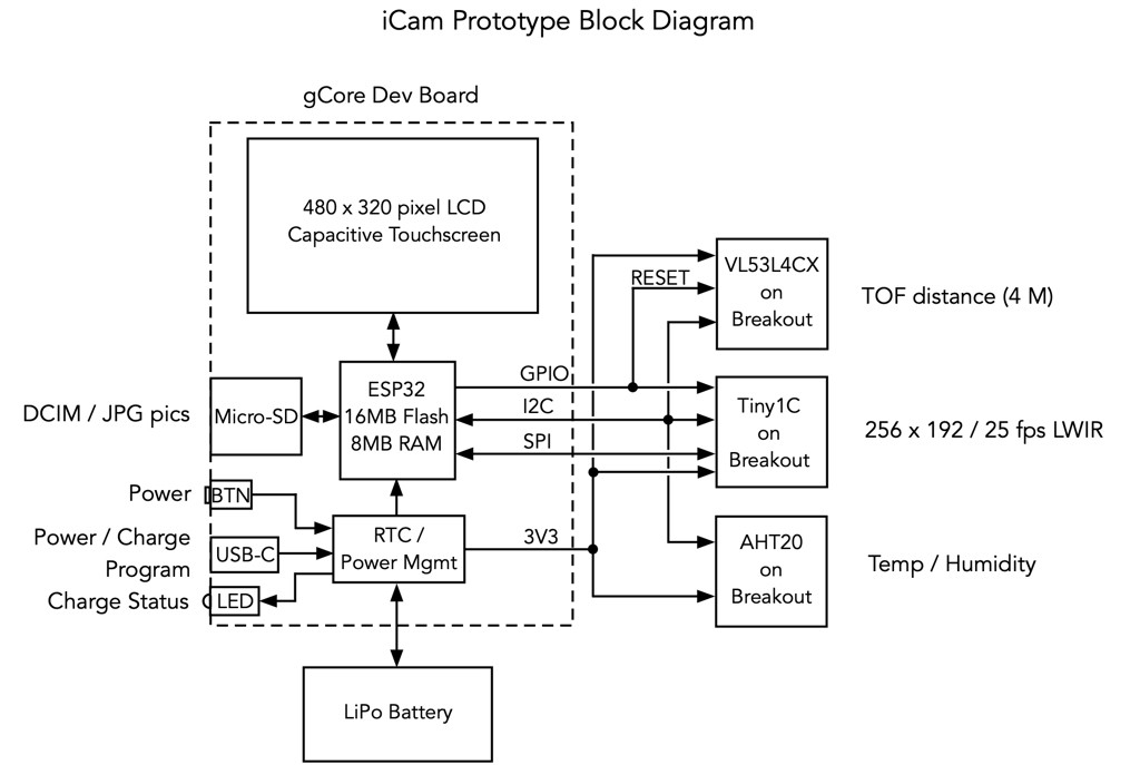
It utilizes a ESP32 Pico module with 8 MB Flash and 2 MB PSRAM.
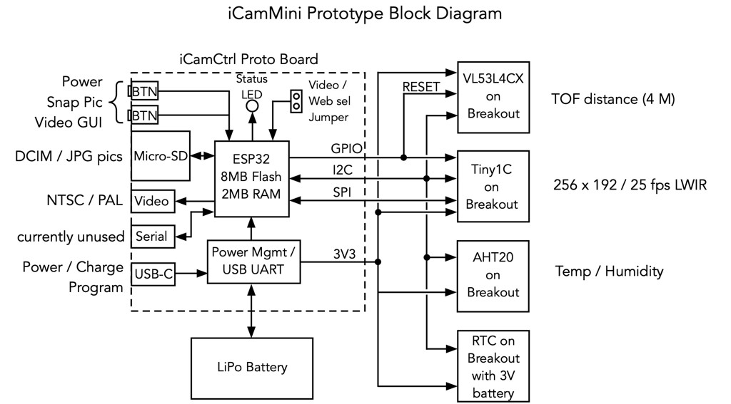
Block Diagram
![]()
I'm currently designing a Rev 2 that fixes some issues and integrates the RTC and backup battery.
iCamMini has several hardware interfaces.
- USB-C for power/charging and programming via a CH340K USB UART.
- Video Output
- CMOS Serial port with flow-control. Currently this is unused.
It can be powered from a variety of sources
- USB-C
- 3.7V Li-Po battery
- 5V through the video output port
- 5V through the serial port
All inputs are reverse diode protected and multiple can be powered simultaneously without reverse flow. The idea is to make the camera easily powered by other devices, for example a video transmitter might output 5V for the analog camera.
A jumper, sampled at boot, selects between Wi-Fi or Video mode.
It has two LEDs and two multi-function push-buttons for local control. The push buttons are used to control power, take a picture (stored as a JPG file in the local Micro-SD card), reset the Wi-Fi to default settings and control setting some camera parameters when the video output is active. One LED indicates charge mode (directly controlled by the TP4056 charger controller IC) and the other, red/green LED indicates various status or fault conditions under control of the ESP32.
Soft Power Control
Soft power control allows firmware to shut down the camera (for example for a critically low battery condition). It is implemented using a pair of P-channel MOSFETs that act as a high-side switch between incoming power and the internal 3.3V regulators. One is switched on whenever one of the push buttons is pressed. The other is switched on under control of the ESP32. The user presses the power button and the ESP32 starts to boot. The first thing firmware does after booting is to switch the other MOSFET on and then light the LED to indicate to the user power is on. Then the user can let go of the power button. This takes a fraction of a second. The ESP32 can also sense the state of the push button so it can detect a long-press (or other software command) to switch off power and turn off the second MOSFET (after waiting for the switch to be released). A side-effect of this method is that the power button has to be held closed while loading firmware.
The other button is a purely software read peripheral.
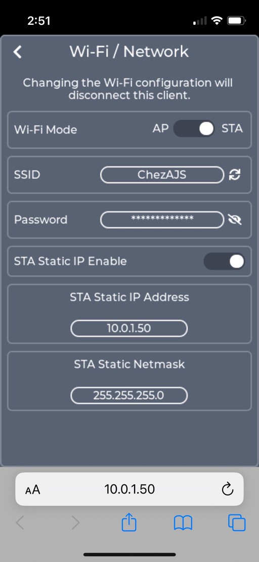
Wi-Fi Mode GUI
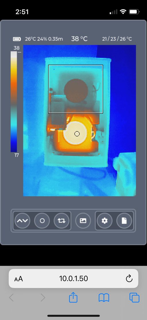
In Wi-Fi mode the camera runs a simple web server that can be connected to by a single desktop or mobile browser. The same LVGL GUI as iCam, but slightly resized based on the browser, is displayed through the magic of websockets and emscripten. It supports rotation for mobile devices.
![]()
![]()
Video Interface
The video interface is designed to drive a 75-ohm video device like a monitor or transmitter. In actuality the Rev 1 prototype can't quite achieve the 1v p-p required voltage range because I was overloading the DAC output so the Rev 2 includes a video amplifier.
![]()
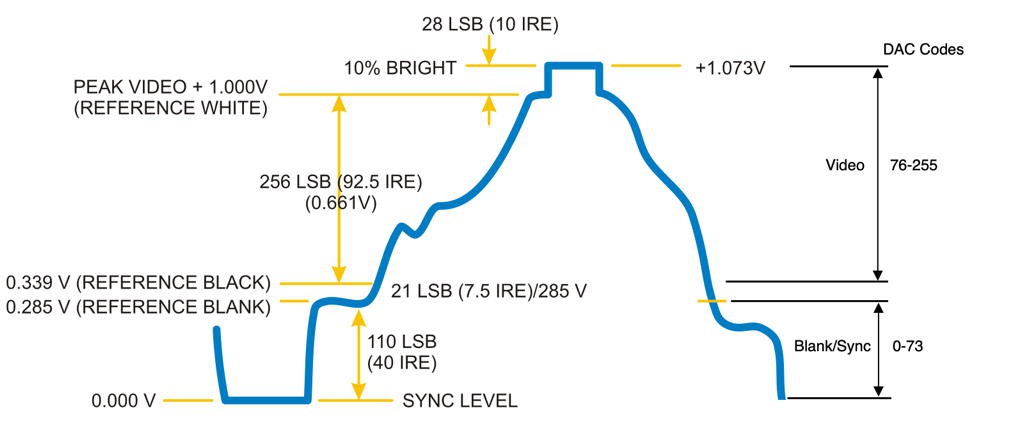
The video output is generated using the ESP32 8-bit DAC and DMA engines with heavily modified code that started out as aqauticus' ESP32 composite video library. The original code could only display 51 brightness levels. My code can display 170 brightness levels. The reason all 256 DAC output codes can't be used for video levels is that some of the signal has to be used for blanking and sync control as shown below.
![]()
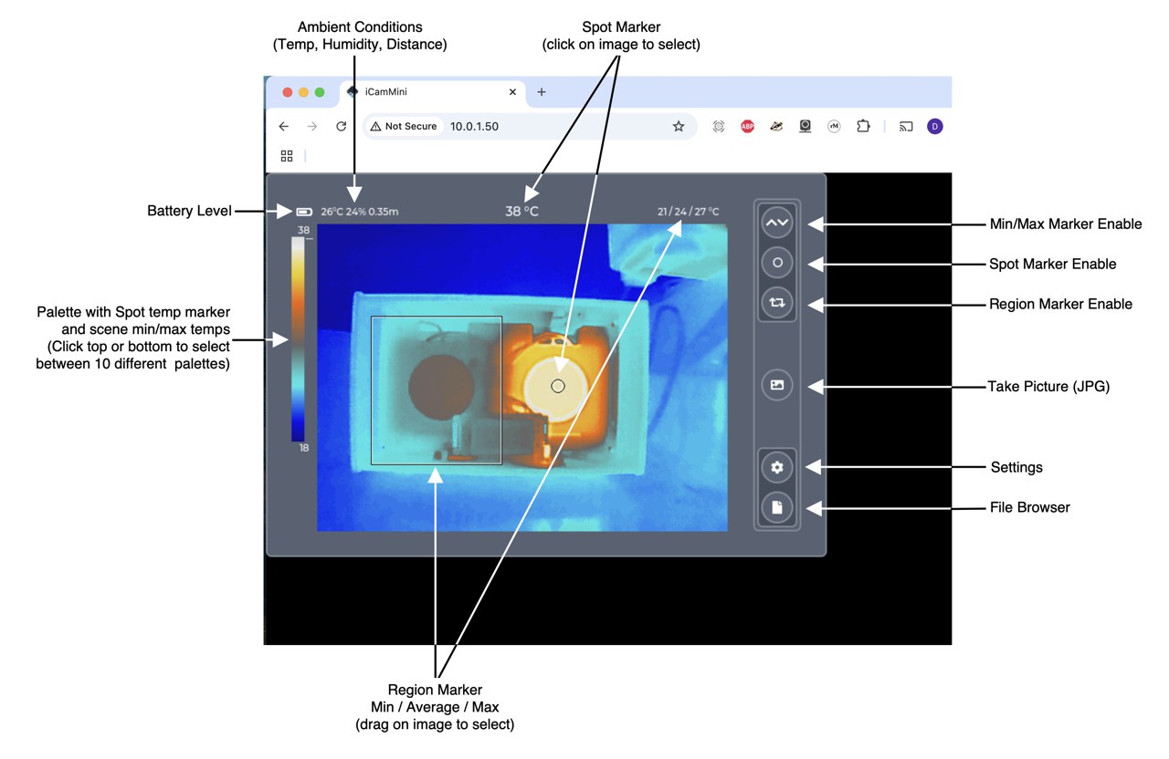
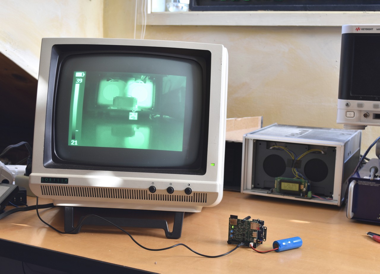
The output can display a spot meter and temperature, the palette with min/max temperatures and min/max markers showing the hottest and coldest points in the image.
Since the output is monochrome-only I can only support two palettes: white-hot and black-hot. I looked at supporting color but the limited DAC range would essentially force the use of only one palette unless I was willing to significantly reduce the number of displayed colors at a time.
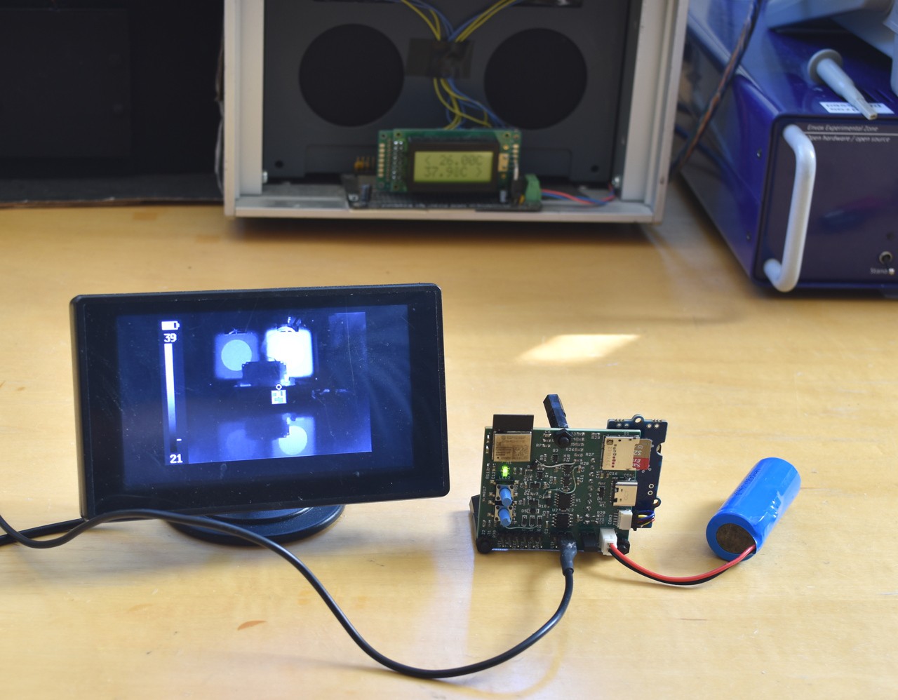
It was fun to connect it to an old CRT monitor and see it work- felt very old-school. This picture doesn't do it justice.
![]()
-
iCam Prototype
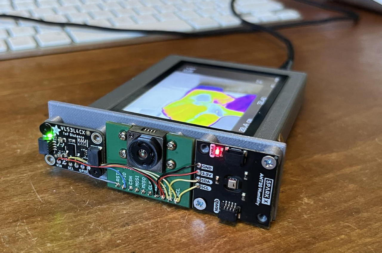
11/19/2024 at 22:12 • 0 commentsThe iCam prototype consists of one of my gCore development boards in a hacked prototype 3D printed enclosure wired to a sensor assembly consisting of the TIny1C breakout, an Adafruit VL53LC4X time-of-flight distance sensor (0-6m) and a Sparkfun AHT20 temperature/humidity sensor.
![]()
This camera is designed to be handheld for portable use with a portrait display
![]()
Hardware is pretty simple.
![]()
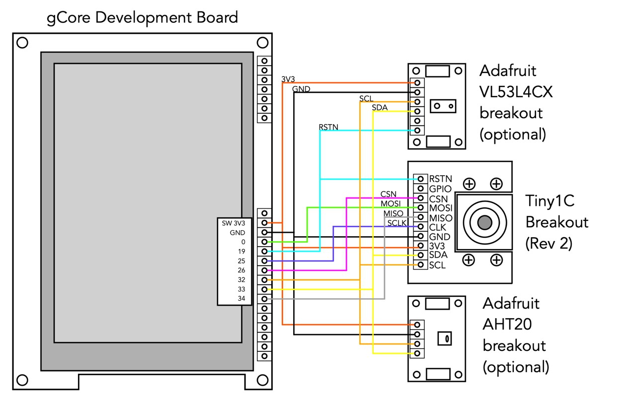
Essentially the gCore supplies 3.3V to the sensors which is switched on when it is switched on, a SPI interface for the Tiny1C VOSPI and a "sensor" I2C bus for all three devices. Another I2C bus exists on gCore for access to the touchscreen controller and RTC/PMIC controller.
It turns out the VL53L4CX has a strange functionality in that once initialized, further initialization sequences can corrupt the internal calibration. To manage this I connect the SHUTDOWN pin on the VL53L4CX breakout (which essentially functions as a hardware reset) to the Tiny1C breakout reset and the firmware resets both devices before any initialization.
My hardware prototype has two push buttons connected to inputs on gCore. They were used with some test software I wrote using the Arduino ESP32 environment because I didn't have the touchscreen input running but are unused in the current Espressif IDF camera firmware.
The following wiring diagram shows specifically how it is connected (this time using an Adafruit AHT20 breakout which might be slightly more available).
![]()
Currently the firmware treats the VL53L4CX and AHT20 as optional peripherals. It can use them to feed a compensation algorithm if they're present but functions without them as well.
In the long haul I plan to design a different closure to capture all the hardware. It's possible the screen orientation might change to landscape although I prefer the way the portrait type of camera is held as opposed to the traditional SLR style. The advantage of the landscape orientation is that I could design a very simple PCB that would connect gCore to the sensor breakout boards (or even include the breakout board components directly).
-
Introducing the Tiny1C and breakout
11/19/2024 at 21:16 • 0 commentsTiny1C
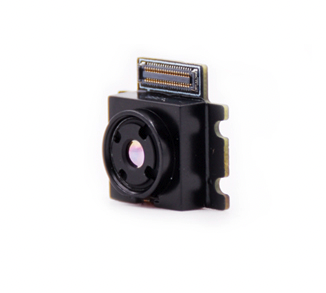
The Tiny1C thermal imaging module (bolometer) by Infiray (or IRayTek - its been hard for me to understand the web of companies) is a small, low-cost, device like the Flir Lepton but with slightly higher resolution and faster frame rate.
![]()
From its datasheet
- 256x192 or 160x120 pixel resolution (I'm using 256x192 pixel models)
- 2.0 F1.1, 3.2mm F1.1 or 4.3mm F1.2 lens (I've been using the 3.2 F1.1 lens)
- 12μm Wafer-Level Packaged (WLP) uncooled Vanadium Oxide (VOx) Uncooled Infrared Focal Plane Detector
- 8~14μm LWIR range
- <40mK @25°C Noise Equivalent Temperature Difference (NETD)
- 8-bit parallel DVP or SPI video interface (I'm using the SPI interface)
- I2C Command and Control interface
- 16-bit YUV422, 14-bit radiometric output or 10- or 14-bit raw data mode (I am using raw data mode)
- Built-in image processing pipeline (I'm using this to sharpen the image and perform AGC calculations)
- -15°C ~ 150°C (High Gain) or 50°C ~ 550°C (Low Gain) range
- +/- 2°C or 2% typical measurement accuracy
- Built in shutter for flat field correction (FFC)
- Typical 240 mW power consumption (600 mW during FFC)
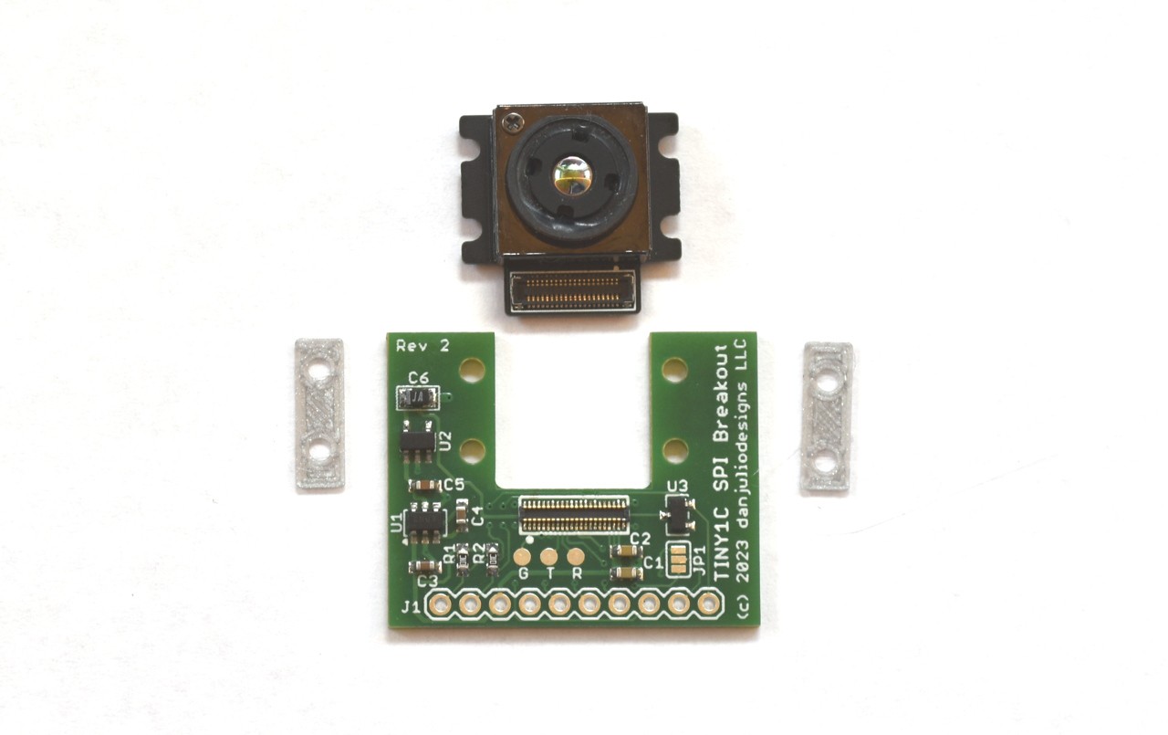
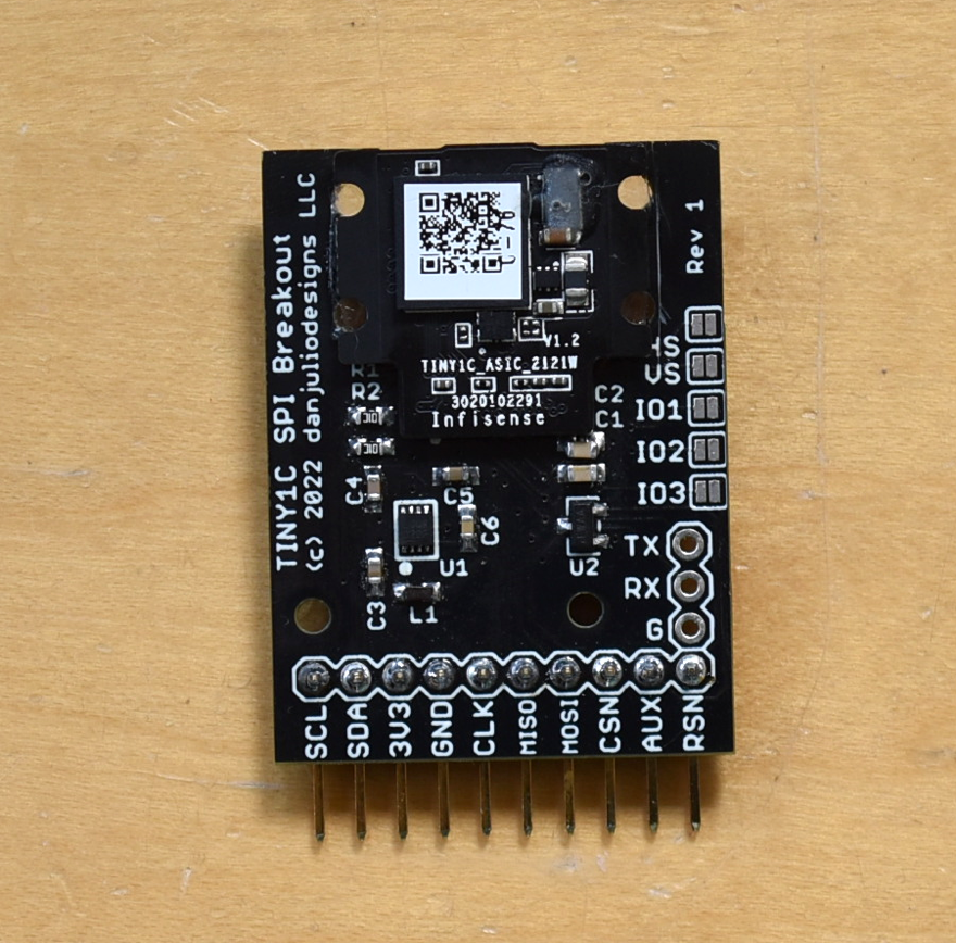
Breakout Board (rev 2)
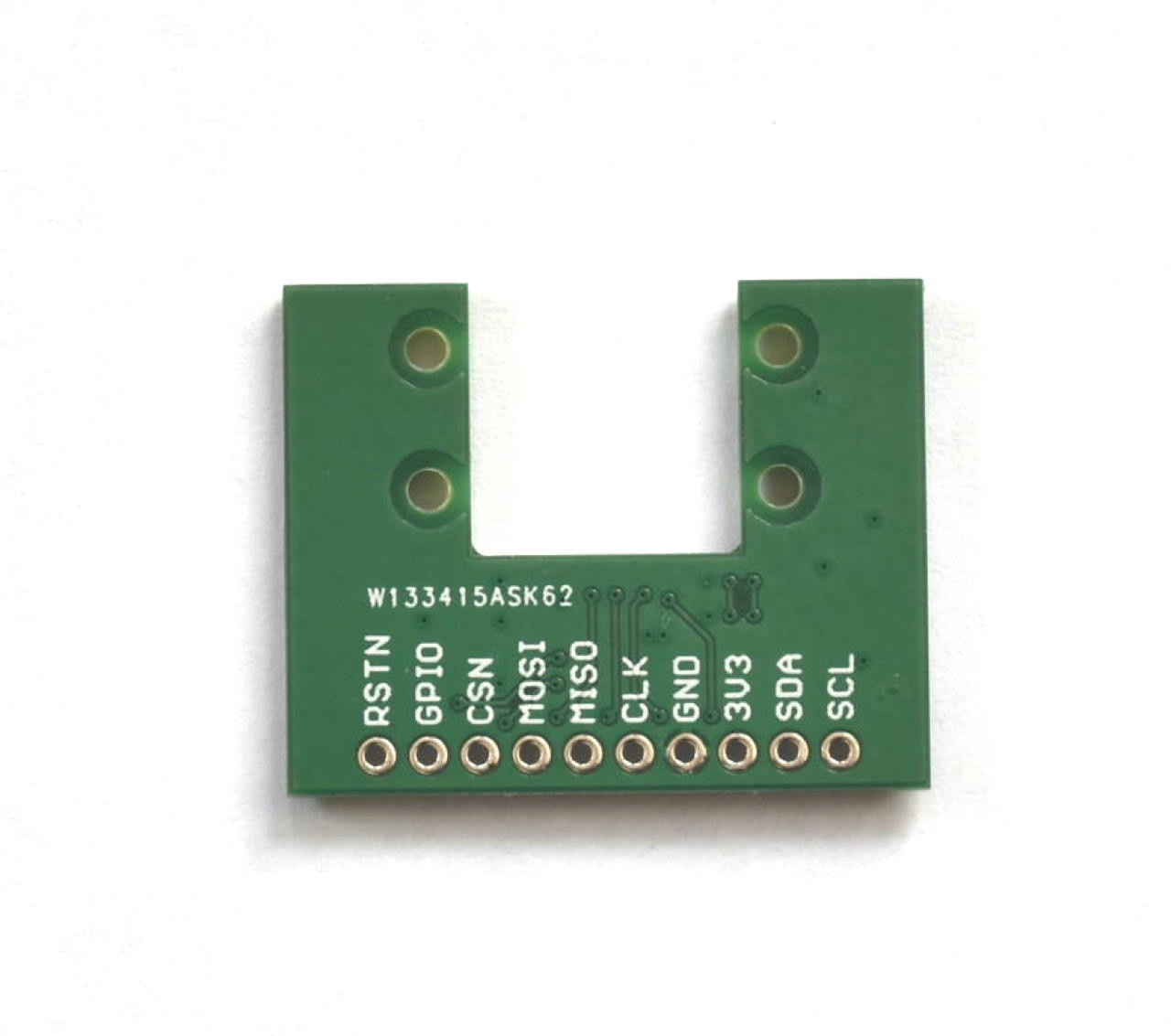
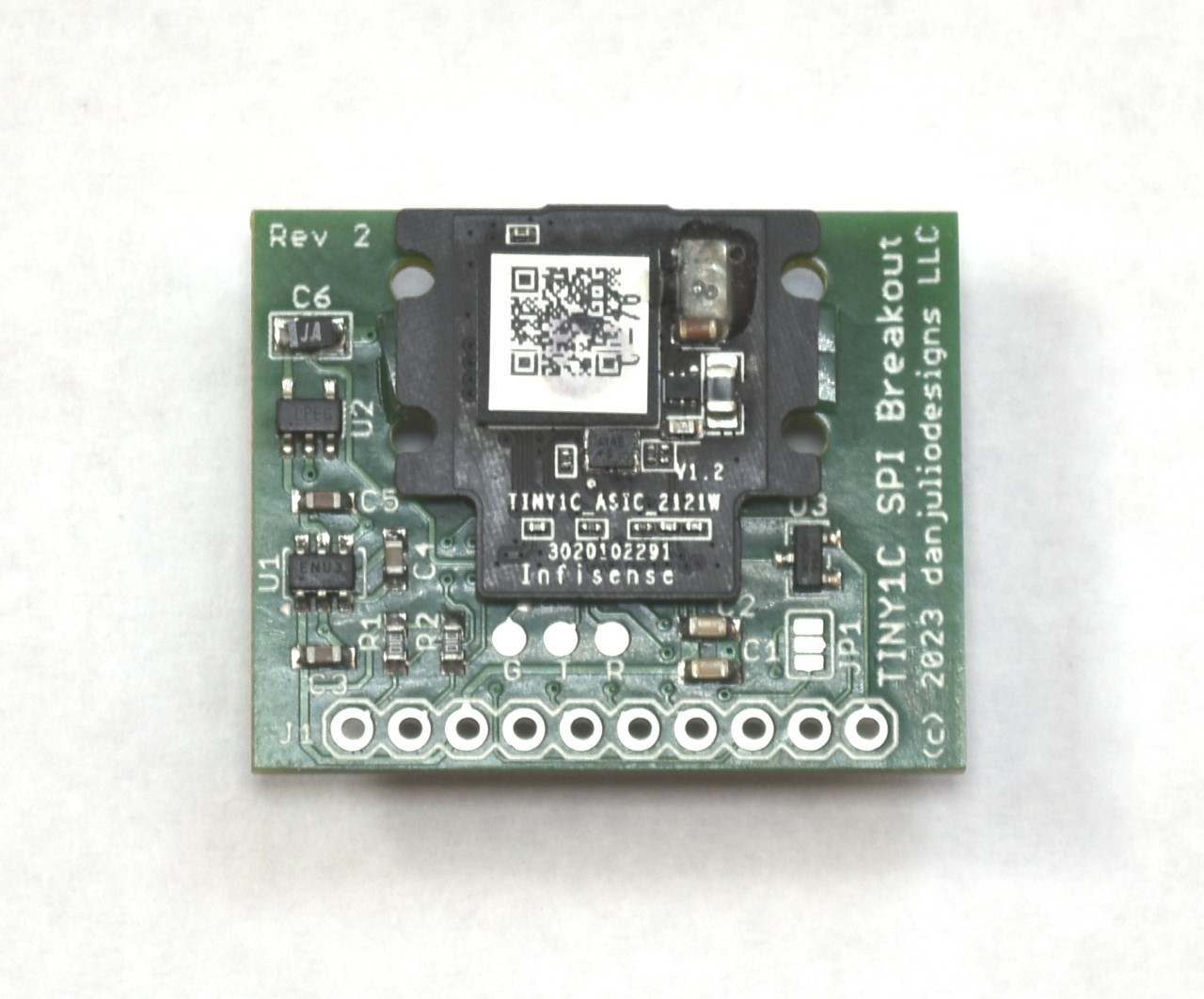
I designed a 1.25 x 1" (32x25.4mm) breakout board loosely modeled on the Lepton breakout board to expose the power, SPI and I2C interfaces. It also makes available the module's serial interface (which outputs some log info but otherwise seems un-useful) and some GPIO pins which seem currently unused.
![]()
![]()
The Tiny1C requires a 3.3V logic power supply and a very low-noise 5V low-current analog supply. The breakout board uses a capacitive boost converter followed by a very low noise linear regulator to generate the 5V from the 3.3V supply. The breakout board also includes a power-on reset pulse generator which is also useful for the distance sensor (as I found out part-way through coding).
![]()
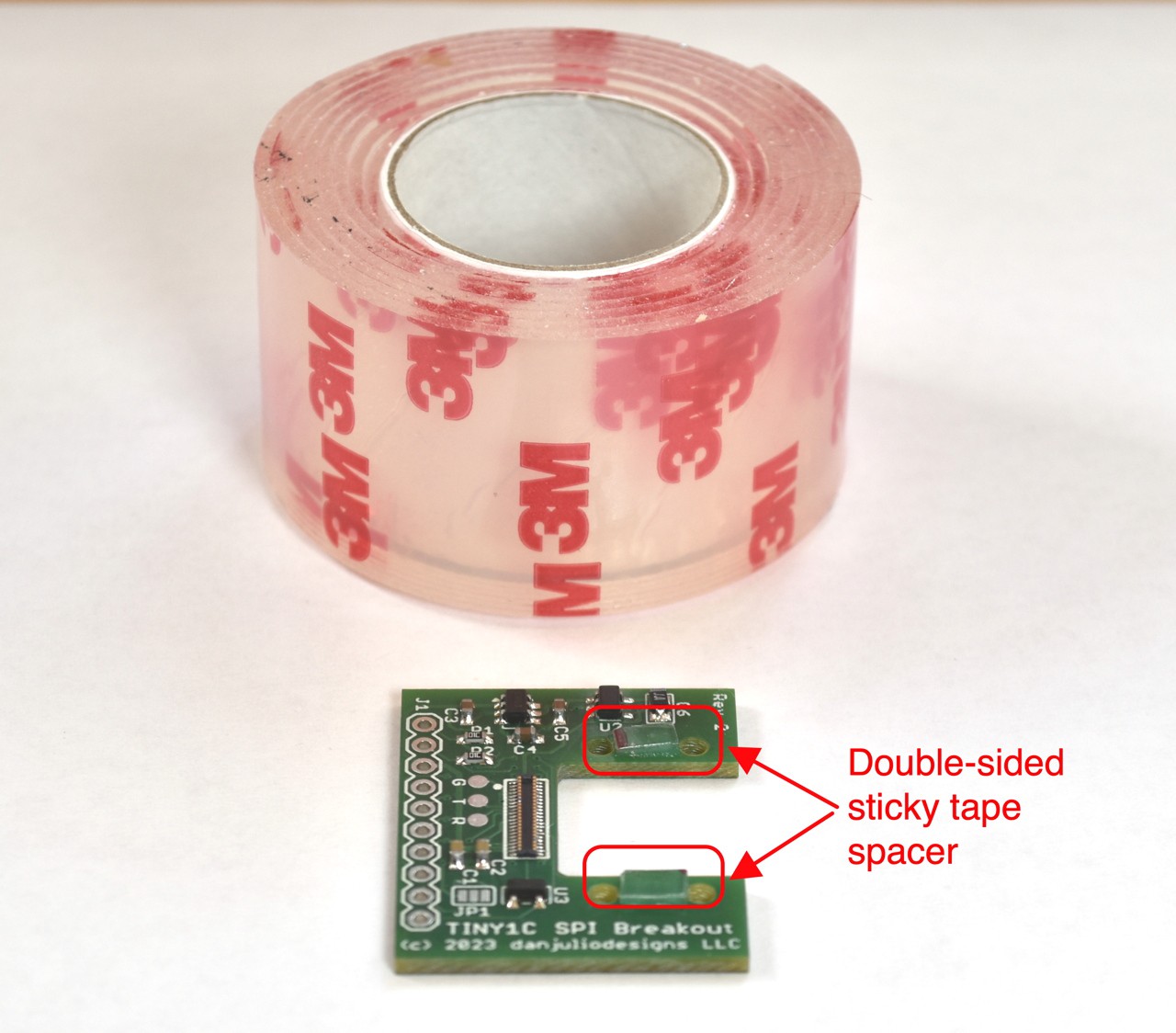
The Tiny1C connects using a very small press-fit connector and I designed a set of 3D printed shims to properly space the module from the board. I also use my favorite 3M double-sticky tape when I'm not screwing the breakout board into an enclosure or holder.
![]()
Some extras available (as of Nov 19 2024)
I have a few extra assembled boards that I can make available for pretty cheap (no Tiny1C modules). Contact me if you're interested. I'll delete this section once they're gone.
Breakout (rev 1)
The first version was a monster compared!
![]()
More accurate thermal imaging cameras
A pair of calibrated thermal imaging cameras with ambient correction based around the Tiny1C thermal imaging sensor.